Faculdade de Ciˆencias
Departamento de F´ısica
Design and Fabrication by Inkjet
Printing of Electrodes for
Electromyography
Jo˜ao Pedro Alves Martins
Disserta¸c˜ao
Mestrado Integrado em Engenharia Biom´edica e Biof´ısica
Engenharia Cl´ınica e Instrumenta¸c˜ao M´edica
Faculdade de Ciˆencias
Departamento de F´ısica
Design and Fabrication by Inkjet
Printing of Electrodes for
Electromyography
Jo˜ao Pedro Alves MartinsDisserta¸c˜ao orientada por
Dr. Ana Teresa Pereira Prof. Dr. Hugo Ferreira
Mestrado Integrado em Engenharia Biom´edica e Biof´ısica
Engenharia Cl´ınica e Instrumenta¸c˜ao M´edica
A utiliza¸c˜ao de impressoras de jacto de tinta (inkjet printers) tem dado um enorme con-tributo na ind´ustria electr´onica reduzindo as dimens˜oes dos componentes e introduzindo processos de fabrica¸c˜ao mais r´apidos e menos dispendiosos. Uma das grandes vantagens deste m´etodo de fabrica¸c˜ao ´e a facilidade de design dos circuitos, a deposi¸c˜ao de materi-ais directamente no substrato sem haver contacto, a sobreposi¸c˜ao de desenhos impressos e a versatilidade de materiais utilizados, tirando o maior partido das suas caracter´ısticas. Duas formas de tirar partido das funcionalidades de uma impressora inkjet, em engen-haria biom´edica, ´e, por um lado, desenvolver circuitos el´ectricos desenhados especial-mente para aquisi¸c˜ao de sinais fisiol´ogicos. Esses circuitos, aliados `as capacidades da impress˜ao por jacto de tinta, poder˜ao resultar em electr´onica flex´ıvel com materiais com elevada biocompatibilidade, promovendo desta forma uma pr´oxima interac¸c˜ao com o corpo humano. Por outro lado, as aplica¸c˜oes da impressora inkjet podem levar ao de-senvolvimento de el´ectrodos impressos enquadrando-os no conceito de pele electr´onica, isto ´e, integrar dispositivos electr´onicos utilizando caracter´ısticas da pele humana (flexi-bilidade, extensibilidade e compatibilidade). Assim, o principal objectivo deste trabalho ´e fabricar, utilizando esta t´ecnica, el´ectrodos com a capacidade de medir sinais electro-miogr´aficos dos m´usculos respons´aveis pelo movimento da m˜ao e dedos. A fim de utilizar as potencialidades da tecnologia inkjet, os el´ectrodos devem obter medi¸c˜oes congruentes do ponto de visto fisiol´ogico e devem se mostrar vantajosos face aos, j´a convencionais, el´ectrodos descart´aveis.
A finalidade da constru¸c˜ao destes el´ectrodos dever´a preencher a carˆencia que os el´ectrodos convencionais possuem, de n˜ao serem flex´ıveis e de n˜ao serem utilizados durante lar-gos per´ıodos de tempo. As vantagens extra´ıdas de el´ectrodos impressos poder˜ao ainda ser mais vastas n˜ao s´o a n´ıvel econ´omico, pela constru¸c˜ao de el´ectrodos low-cost, mas tamb´em a n´ıvel de desempenho, biocompatibilidade e design, com o desenvolvimento de el´ectrodos finos, paper-like e passiveis de acoplarem circuitos electr´onicos tamb´em impressos.
O desenvolvimento do trabalho apresentou uma variedade de tarefas, com inicio na aprendizagem dos conceitos e m´etodos de funcionamento da impressora Fujifilm Di-matrix 2831 Materials Printer. Esta impressora, utilizada para obten¸c˜ao de todos os el´ectrodos e circuitos aqui referidos, possui uma tecnologia drop-on-deman coordenada por material piezoel´ectrico, conseguindo uma resolu¸c˜ao at´e∼5 µm. As voltagens induzi-das a este material tem um enorme impacto na forma¸c˜ao das gotas de tinta, e por isso a uma boa qualidade de impress˜ao. No entanto, outros factores como a viscosidade
As tarefas seguintes inclu´ıram a optimiza¸c˜ao dos procedimentos para tratamento dos sub-stratos de forma a que a deposi¸c˜ao da tinta de prata fosse ´optima. Os substratos utiliza-dos neste trabalho foram: papel fotogr´afico, biocelulose e polidimetilsiloxano (PDMS). Tamb´em os m´etodos de impress˜ao tiveram que ser optimizados controlando a velocidade e a direc¸c˜ao da deposi¸c˜ao das gotas de tinta. Uma vez que foi apenas utilizado um tipo de tinta prata, uma dispers˜ao de nanoparticulas de prata, foi utilizada a mesma veloci-dade de deposi¸c˜ao das gotas, 10 m/s com temperatura do tinteiro constante, de 30◦C. Por fim, houve necessidade de melhorar o processo de sinteriza¸c˜ao que visa a remo¸c˜ao do solvente e outras substˆancias presentes na tinta de prata, e que tem enorme impacto na resistividade final do padr˜ao impresso. Um bom processo de sinteriza¸c˜ao faz com que as nanoparticulas de prata tenham um forte contacto entre elas, aumentando con-sideravelmente a conductividade do material. Para este fim, foi testada a sinteriza¸c˜ao t´ermica padr˜ao e introduzida um novo m´etodo, a sinteriza¸c˜ao el´ectrica cuja aplica¸c˜ao de uma diferen¸ca de potencial permite a passagem de corrente el´ectrica gerando calor localmente.
Para impress˜ao de el´ectrodos, os seus designs foram adaptados `as caracter´ısticas dos materiais, sendo que, por exemplo, para materiais mais flex´ıveis foram implementadas conex˜oes serpenteadas entre pequenos el´ectrodos. Para outros substratos, como o pa-pel fotogr´afico, foi optado um design semelhante ao dos el´ectrodos convencionais para obter melhor termo de compara¸c˜ao. J´a para aplica¸c˜ao de sinteriza¸c˜ao el´ectrica, optou-se por um design que consiste num ´unico filamento para que seja poss´ıvel a aplica¸c˜ao de uma diferen¸ca de potencial em ambas as extremidades. Durante o aperfei¸coamento dos el´ectrodos, foi elaborado uma s´erie de estudos acerca das caracter´ısticas dos mesmos (resistividade e impedˆancia) e as suas medi¸c˜oes foram comparadas com os resultados obtidos, em condi¸c˜oes semelhantes, aos el´ectrodos tipicamente utilizados em ambiente cl´ınico. Como resultados de medi¸c˜oes de sinais electrocardiogr´aficos, os el´ectrodos im-pressos em papel fotogr´afico mostraram-me vantajosos quanto `a morfologia do tra¸cado, pois o termo de compara¸c˜ao foi similar aos obtidos por el´ectrodos convencionais. No estudo de sinais electromiogr´aficos, os el´ectrodos impressos em biocelulose e papel fo-togr´afico tiveram taxas de sinal-ru´ıdo abaixo das obtidas pelos tradicionais el´ectrodos de uso cl´ınico. Ainda assim, os dados dos el´ectrodos impressos podem ser utilizados para capta¸c˜ao de sinais fisiol´ogicos pois foi poss´ıvel demonstrar a extrac¸c˜ao de informa¸c˜oes acerca do movimento dos m´usculos esquel´eticos e card´ıaco. Contudo, n˜ao foi poss´ıvel a obten¸c˜ao de sinais fisiol´ogicos utilizando el´ectrodos impressos em PDMS. Devido a
Tarefas interm´edias inclu´ıram a impress˜ao de pequenos circuitos electr´onicos, nomeada-mente um circuito impresso cuja principal fun¸c˜ao ´e a leitura e tratamento (ampli-fica¸c˜ao e filtragem) de sinais electrocardiogr´aficos. Dois outros circuitos, mais simples, foram impressos: um d´ıodo emissor de luz e um sensor de luz. Todas as pistas de condu¸c˜ao de ambas as camadas foram impressas com prata em papel fotogr´afico e os componentes electr´onicos foram colados com cola de prata. A optimiza¸c˜ao deste pro-cesso poder´a trazer enormes vantagens pela possibilidade de constru¸c˜ao de circuitos electr´onicos flex´ıveis e finos com el´ectrodos incorporados.
Por fim, a ´ultima tarefa inclui processamento de sinal a qual inclui a implementa¸c˜ao de algoritmos em ambiente MatLab para extrac¸c˜ao de movimentos dos m´usculos do antebra¸co. Com a informa¸c˜ao extra´ıda por trˆes movimentos distintos da m˜ao foi provado que os el´ectrodos impressos podem ser usados para posterior reconhecimento de padr˜oes. A distin¸c˜ao dos trˆes movimentos foi feita com sucesso, sobretudo para os el´ectrodos impressos em biocelulose e para os el´ectrodos de baixa resistividade em papel fotogr´afico. Este trabalho tamb´em abriu portas para investiga¸c˜oes futuras em que mais substratos e tintas podem ser testadas e mais componentes podem ser integrados aos j´a aqui desen-volvidos. Desta forma, a tecnologia inkjet pode contribuir com a sua versatilidade para a inova¸c˜ao nos campos electrofisiologia e das interac¸c˜oes homem-m´aquina.
Inkjet technology has advantages as a fabrication method when compared to other con-ventional procedures. Inkjet technology allows the deposition of several materials di-rectly with non contact with it, mask-less and the possibility of printing over a previous printed pattern [1]. Due its versatility of inks (conductive, polymers and organic) and substrates, direct deposition of materials with high precision (∼5 µm) using simple methods, this technique shows a high potential as a fabrication method. Despite the wide range of applications of inkjet printing in electronics, a lack of intend for printing devices for collecting biosignals. The subject of the work presented was the first step towards the development of a inkjet device for a close contact with skin for collecting biosignals.
One way to apply the functionalities of an inkjet printer, in biomedical engineering, is developing printed electrodes introducing electronic skin concept, i.e., implement elec-tronic devices using features of elecelec-tronic skin (flexibility, extensibility and compatibil-ity). Thus, the major goal of this work was develop, using this technique, electrodes capable of measuring electromyographic signals from the forearm’s muscles responsible to move hand and fingers. In order to use the potentials of inkjet technology, these electrodes must obtain congruent measurements and should prove advantageous when compared to the standard electrodes. The versatility of inkjet printing allowed to print electrodes, using a inkjet printer DMP-2831, onto substrates that included photographic paper, biocellulose and PDMS and test the performance of different designs: standard flat discs, spiked, filamentary and serpentine array of small electrodes.
This thesis presents the development of tasks that includes the design and choice of materials, optimization of printing and sintering procedures, printing electronic circuits and ends with signal processing. During the optimization of the electrodes measure-ments of resistivity and impedance were performed to understand the behaviour and characteristics of them. Finally, a linear discriminant analysis was used to successfully distinguish between three hand movements.
It is my pleasure to acknowledge all the persons that made this work possible and permitted me to carry it until the end with the same enthusiasm.
Firstly, I would like to express my sincere gratitude to my supervisors Ana Teresa Pereira and Hugo Ferreira for the continuous support, their availability to teach, patience, mo-tivation, enthusiasm, and immense knowledge. Their guidance helped me through all the time of this work.
I would like to acknowledge Prof. Lu´ıs Alc´acer, Ana Lu´ısa, Jo˜ao Bastos, Tˆania Braz, Gra¸ca Brotas and all members of Organic Electronics Group, Instituto de Telecomu-nica¸c˜oes, by making me feel at home from the first day, for their scientific and techno-logical teaching and because their friendship made work easier. My thanks also goes to Andr´e Louren¸co, Hugo Silva and Ana Priscila from Pattern and Image Analysis Group, Instituto de Telecomunica¸c˜oes, for their enthusiasm and belief in my work.
I would like to acknowledge my family, my parents Maria Jos´e and Lidio, my brother Edgar and my grandmother, Maria for always being present my entire life. To my parents in law, Fernando and Manuela, for their practical help and comprehension. Last but not least, I finish by thanking to the love of my life, Joana, for her unconditional support and encouragement.
I would like to acknowledge to FCT for partly funding this work with the following project reference PTDC/CTM/102144/2008.
Resumo ii
Abstract v
Acknowledgements vi
List of Figures x
List of Tables xii
1 Introduction 1 1.1 Inkjet Technology . . . 1 1.1.1 Continuous inkjet . . . 4 1.1.2 Drop on demand . . . 5 1.1.2.1 Thermal inkjet . . . 6 1.1.2.2 Piezoelectric inkjet . . . 6 1.2 Electrodes . . . 9 1.2.1 Conventional electrodes . . . 11
1.3 State-of-Art of non conventional electrodes . . . 13
1.4 Electromyography . . . 16 1.5 Motivation . . . 19 1.6 Outline . . . 20 2 Printed Electrodes 21 2.1 Materials . . . 21 2.1.1 Ink . . . 22 2.1.2 Substrate . . . 24 2.1.2.1 Photographic paper . . . 24 2.1.2.2 Polydimethylsiloxane . . . 25 2.1.2.3 Biocellulose . . . 26 2.2 Design Characteristics . . . 27 2.3 Fabrication Procedure . . . 30 3 Electrodes’ characterization 33 3.1 Resistivity . . . 33 3.2 Impedance . . . 36 3.3 ECG measurements . . . 39 3.4 EMG measurements . . . 40 viii
4 Signal Processing 45 4.1 Movement detection . . . 45 4.2 Feature extraction . . . 47 4.3 Classification . . . 49 5 Printed Circuits 52 5.1 Fabrication Procedure . . . 53 5.2 Circuit performance . . . 54 6 Conclusions 56 6.1 Main results . . . 56 6.2 Applications . . . 58 6.3 Future Work . . . 58 Bibliography 60
A Electrode data sheet 65
B MATLAB code 70
C CONFTELE paper 76
1.1 Classification of inkjet printing technologies . . . 3
1.2 Diagram of a single-jet of continuous inkjet printer . . . 4
1.3 Diagram of a drop-on-demand print head . . . 6
1.4 Three types of piezoelectric inkjet. . . 7
1.5 Piezoelectric inkjet with shear mode. . . 8
1.6 Ink drop behaviour in contact with hydrophilic and hydrophobic surfaces 9 1.7 Layers involved on the interaction electrode-skin . . . 11
1.8 Spiked electrodes . . . 12
1.9 Electric properties of the electrode-skin interface . . . 13
1.10 Electronic skin . . . 14
1.11 Fabrication process scheme of the inkjet printed stretchable silver electrodes 15 1.12 Structures responsible for promoting an EMG signal . . . 18
1.13 EMG detection . . . 19
2.1 Fujifilm Dimatrix 2831 Materials Printer . . . 21
2.2 Sintering process of nanoparticles silver ink . . . 24
2.3 The chemical structure of PDMS . . . 25
2.4 Printed lines in a surface with different hydrophobicity . . . 26
2.5 Nanofiber network of biocellulose . . . 27
2.6 Printed flat disc electrode . . . 28
2.7 Printed electrode with one continuous filament . . . 28
2.8 Printed electrode array . . . 29
2.9 Printed spiked electrode . . . 29
2.10 Printed electrode for galvanic resistance measurements . . . 30
2.11 Electrodes placed on armlet . . . 32
3.1 Patterns used to measure silver’s resistivity . . . 34
3.2 Nyquist plot for printed electrodes . . . 38
3.3 Plot of resistance according to frequency for printed electrodes . . . 38
3.4 Electrode leads placement for ECG measurements . . . 39
3.5 ECG signal frequency spectrum for both acquisition devices . . . 40
3.6 EMG signal recorded with commercial and spiked electrodes . . . 41
3.7 Signal-to-noise ratio of commercial and spiked electrodes . . . 42
3.8 Signal-to-noise ratio of several electrodes . . . 43
4.1 Onset times using Bonato method in EMG measurements . . . 46
4.2 Movements extracted from a EMG experience . . . 47
4.3 Hand movement subjected to Linear Discriminant Analysis . . . 50 x
4.4 Linear Discriminant Analysis result for movement 1 versus movement 2
and 3 . . . 50
4.5 Linear Discriminant Analysis result for movement 2 versus movement 3 . 51 5.1 The BITalino platform . . . 52
5.2 Printed circuit pattern . . . 53
5.3 ECG printed circuit . . . 54
1.1 Comparison between patterning techniques . . . 3 3.1 Average values of sheet resistance and resistivity of printed squares . . . . 34 3.2 Average values of sheet resistance and resistivity of printed lines . . . 36
Introduction
1.1
Inkjet Technology
Nowadays, the standard fabrication procedures of electric circuits, as screen printing, photolithography and electrotyping use masks techniques to create different regions on the substrates: conductive and non conductive regions. Those techniques might have disadvantages in terms of efficiency because are slow procedures with, sometimes, the use of several different materials with a high waste of materials that are deposited; environmental whereas some procedures require the usage of polluting solvents to mask removal. Conventional techniques have lack of simplicity of the entire procedure [2], and lack of application of organic electronics where the compatibility between solvents for the photoresist and the materials that is being deposited is critical. Even simpler techniques like transfer printing require previous procedures as lithography to build the molds.
Therefore was a need to create a simpler fabrication procedure in which a conductive material deposition with a certain shape and dimension directly on a substrate: inkjet printing.
Since the invention of the letterpress with movable lead type, printing technology has kept up the development of computerized information. This technological breakthrough lead to the abandonment of physical printing masters or printing plates for every type of information to be produced. Therefore conventional printing had key disadvantages as large financial and time investments to produce printing masters and complex working steps [3].
Unlike conventional printing technology, digital printing didn’t need pre-manufactured masters or a significant impact force on the substrate to transmit information. The
solution for the non use of printing masters was achieved by an accurate positioning of a small volume of a liquid droplet directly on the substrate [3].Today, inkjet technology is a familiar method for printing text and images onto porous surfaces like paper, directly from computer software, as a sort of writing [4].
Using the same principle as the graphic arts industry, electronic print technology adopted a similar way to deposit different materials onto different substrates besides paper [5]. This free-form fabrication method has been used for building three-dimensional struc-tures and has being explored as a way of printing electrical and optical devices [6].The inkjet is a material’s conservation and deposition technique only used for liquid phase materials, where the solute is either dissolved or dispersed in a solvent. The versatility of material inkjet allows the use of organic (polymers, proteins or nucleic acids) and inorganic inks (silver, gold,. . . ) which can be used to develop electronic devices. The printer’s versatility allied to the simplicity of the procedures ensures a great technology for developing either electronic and non electronic devices.
The possibility of printing materials using inkjet technology brought several advan-tages to the manufacturing procedures conventional used, such as photo-lithography and transfer printing. Comparing with those standard techniques for patterning thin films or bulk substrates with high precision, some differences stand out. The appeal of inkjet technology lies in being a non contact printing which implies a lesser risk of material’s contamination, it is a mask-less approach which makes an intuitive procedure, a low temperature process and an addictive procedure, i.e., it is possible to print over a previous printed pattern [5].
Inkjet material deposition printers had the same basic principle of digital printing namely the absence or presence of information at each pixel of the picture (computer data), enabling the deposition of material on a specific localization on a substrate [3]. For these reason, direct write allows the use of thin and flexible substrates but also stiff materials. However, the need for a versatile inkjet technology for forming multilayer devices raises the number of materials problems that before were not applied [6], such as surface tension or the hydrophobicity of the substrate’s surface.
The versatility of printer continues on designs because the structures’ designs are made digitally allowing to change it with ease and instantly. Designs could be made with small dimensions to build, for instance, micro-structures but also large patterns with several centimetres. Material inkjet printers have compatibility with low and large printing areas so is easy to scale patterns to a large area manufacturing. Another attractive feature is the low cost procedure due to the reduction of wasted materials. This feature is implicit on how the printer works because ink’s droplets are only deposited where
Photolitography Shadow Mask Micro-contact Inkjet Printing Printing
Cost Extremely high Low Medium Low Area Extremely small Large Medium Large
Efficiency Low High High High
Temperature High Low Medium Low and high Mask Needed Needed Needless Needless Resolution Extremely high Low High High Compatibility with polymer Bad Good Bad Excellent
Flexibility Bad Bad Bad Good,
digital lithography Compatibility with Roll to roll Bad Medium Good Good
Material consuming Large Medium Low Low Environment Clean room, Low Medium Low
vibration isolation
Process Multi-step Multi-step Multi-step All in one Mode of action Non contact Contact Contact Non contact
Table 1.1: Comparison between patterning techniques [4].
programmed to, whereas in lithography processes the material is deposited over the entire area of the substrate and then removed in the areas where is not desired.
The possibility of printing materials using inkjet technology brought several advantages to the manufacturing procedures conventional used, such as photo-lithography, transfer printing, shadow masks or micro contacted printing (see Table 1.1). The capability of inkjet printing provides a high potential for simplification of fabrication process with small costs.
The main process of inkjet printing involves ink’s storing on a cartridge before the ejec-tion of an exact quantity of ink throw a noozle. Although this is the main principle of function, inkjet printing technology can be classified into two major working pro-cesses: continuous inkjet (CIJ) and drop on demand (DoD) technology (see Figure 1.1). Each working process has several minor categories which are classified according to the principle used to produce droplets. [7].
1.1.1 Continuous inkjet
As the name of inkjet category implies, the continuous inkjet (CIJ) process starts by forming ink drops from a continuously flowing jet of ink that is driven from a nozzle. The process starts with a high-pressure pump that directs liquid ink from a reservoir forcing the liquid to leave throw a nozzle as a form of jet (see Figure 1.2). Imposing a regular disturbance with a defined frequency causes the jet to break up into small ink drops and a uniform stream of drops is produced. If there is no regular disturbance with, for instance, a piezoelectric transducer, small perturbations at a particular wavelength begin to grow and naturally develop along the jet causing the jet to break up. If not controlled, the break up point and the size of formed drops are unpredictable therefore useless. Some parameters are important to calculate the break up point, since it is proportional to nozzle diameter, jet velocity, ink density and ink viscosity [8].
Figure 1.2: Schematic diagram of a single-jet of continuous inkjet printer [8].
During a controlled break up of jet, certain drops from the stream are selected individ-ually for printing inducing electrical charge by having an electrode nearby held at an appropriate potential. When a positive voltage is applied to the charge electrode, the induced charge is retained on the drop resulting in the drops taking a negative charge proportional to the voltage applied [8].
Then the drops pass through a fixed electric field causing a deflection of the charged drop according to their charge while the uncharged drops are captured for reuse. That is the reason why is commonly used electrically conducting ink on CIJ technology. The degree of the drop deflection is determined by the electric field strength which in turn depends on the voltage applied and the distance between the field plates. This way, is produced one line of the image to be printed. By moving the substrate, several lines are successively printed forming the desired image or text. In a more complex system, more jets can be couple to obtain a faster printing [7].
Currently, this type of printing is used to apply some information, as batch codes, dates or product names on individual packages and product on a production line. Yet,
continuous inkjet printing is not used in print electronics as the recycling process after exposure to the environment might result in contamination of the ink [3]. The major advantages are the high speed printing and the existence of a relative long distance between print head and the substrate. From a mechanical point of view, this technique is also advantageous because the risk of clogging the nozzle is too remote due to the continuously flow of ink through it, which allows the use of volatile solvents that dry faster. Finally, CIJ has also the advantage of being able to be used with non-planar geometry substrates. [3].
Although CIJ is a very mature technique and widely used in industry, has troubles fabricating very delicate and high resolution patterns. The main problem is the creation of undesired satellite drops when the continuous jet is breaking up. Is common to find smaller, satellite drops that, depending on inks characteristics, either recombine with the main drop or be deflected to unwanted places causing poor printing resolution or even printing failure. To fix this, attempts to deliberately create and use the satellite drops for high resolution patterning [8].
1.1.2 Drop on demand
Instead of continuously firing drops it is also possible to create drops only when an actuation pulse is provided, the drop-on-demand (DoD)system. Major advantages of DoD printers over CIJ printers include the fact that there is no need for complicated hardware for break up the jet, charging electrodes, deflection plates, capture and re-circulation systems and high pressure pumps. That is a reason why DoD technology in the form of inkjet printing has demonstrated a rapid growth during the last two decades [9].
Drop-on-demand print heads usually have an array of nozzles each of which ejects ink drops only when are required, reducing the fluid’s waste and contamination. An actuator creates a rapid change in the cavity volume and initiates an impulse that propagates pushing a drop of fluid outwards through the nozzle (see Figure 1.3). For the drop overcome the decelerating action of ambient air, its velocity must be few meters per second which depends directly on the amount of kinetic energy transferred [8]. Even so, the entire process of forming drops is in some ways simpler and more intuitive than CIJ system.
Although other methods have been explored, the two most common means to trigger the ejection of fluid is using a heater pad (thermal inkjet) and using the distortion of a piezoelectric elements (piezoelectric inkjet).
Figure 1.3: Schematic diagram of a drop-on-demand print head [8].
1.1.2.1 Thermal inkjet
A thermal inkjet print head typically contain a series of nozzles where behind each exists a tiny firing chamber where the ink ejection process occurs. Each firing chamber consists of a substrate, typically a silicon substrate, a thin film heating resistor, made of tantalum aluminum (TaAl ) by photolitography, ink barriers and a nozzle [10].
Various conductive and insulation layers as well as a resistive layer generating heat are patterned into the substrate. When a few microseconds pulse of electric current passes through the resistive layer, it rapidly heats up raising the plate temperature to about 300oC [6]. This heat energy causes the boiling of the ink forming a bubble of vapour, which results in the formation and ejection of a drop. As the bubble continues to expand and fill the chamber, ink in the chamber is driven out of the nozzle, forming a droplet. After, approximately 10 to 20 µs, the bubble collapses, and the drop of ink is detached from nozzle plate. Then, through a channel new ink enters the chamber refilling it and the procedure is repeated to form a new droplet [7].
The inks are usually water-based and must have a volatile component to form the bubble, otherwise droplet ejection cannot occur. The main problem is to avoid clogging of the nozzle by dried ink. For this reason, the range of ink solvents that could be used in thermal inkjet are less broader then piezoelectric inkjet. Also the high temperature can cause damage to either the ink or the materials around the firing chamber. To minimize chamber’s damage and because the heater layer is normally very fragile, other layers are patterned on top of the heater in order to protect it from thermal and mechanical damage by bubble collapse [3].
1.1.2.2 Piezoelectric inkjet
A piezoelectric inkjet system, as the name implies, uses a piezoelectric material, as actuator, to convert applied externally electrical energy into mechanical deformation of an ink chamber. Behind each nozzle is a piezoelectric material, typically lead zirconium titanate (PZT), instead of a heating element. A chamber filled with a fluid is contracted
due to the displacement of the walls in response to application of an external voltage. The result of a sudden volume change are pressure waves that begin to propagating throughout the capillary [11].
(a) Squeeze (b) Push (c) Bend
Figure 1.4: Three types of piezoelectric inkjet.
Depending on the piezoelectric deformation mode, this type of technology can be clas-sified into four types: squeeze, shear, push and bend. The squeeze mode was the first to be invented and the tubes with a diameter of about 1 mm are radially polarized [7]. When it is desired to have a droplet ejected, a short time voltage pulse is applied and the contraction of the transducer is made radially. The result is a smaller tube that squeezes the ink and a droplet is expelled. Push and bend modes have the same principle, in both the electric field is generated between the electrodes parallel to the polarization of the piezoelectric material. Applying a voltage to the piezoelectric plate results in a con-traction of the plate thereby causing the diaphragm to bend inwardly into the pressure chamber. This bending, once more, applies pressure on the fluid inside the chamber forcing the droplet to come out. In a similar way, in push mode is applied a voltage that expand the piezoelectric material towards the nozzle. The piezoelectric material push a thin diaphragm, to prevent undesirable interaction between the actuator and the ink, which pushes the ink through the orifice [7]. In a shear mode system, the electric field is designed to be perpendicular to the piezoelectric material. If the electric field is applied parallel to the poling field, then the piezoelectric material reacts in extension mode, i.e., the material lengthness in one dimension and shortness in the other. This was the principle to push and bend mode. But if the electric field is applied perpendicular to the poling field, the piezoelectric material reacts in a shear mode which allows a change in only one dimension. This is the main operation principle of print heads in a shear mode [12].
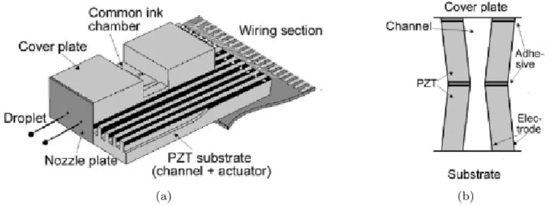
The base plate of this print heads contains multiple ink channels in which metal elec-trodes are deposited on the upper half of both sides of the channel wall. A cover plate is bonded on the upper surface of the walls, and a nozzle plate is bonded on the front surface of the substrat, and the ink is stored in a common chamber. When an electrical
(a) (b)
Figure 1.5: Piezoelectric inkjet with shear mode. (a) Scheme of a piezoelectric inkjet print head with shear mode. (b) Cross section of a channel (PZT). [13].
field is applied in the direction orthogonal to the polarization of the piezoelectric ma-terial, PZT are deformed increasing the channel volume which makes the ink enter the channel. After the generation of the pressure wave, it is propagated between nozzles and the common chamber, changing the pressure consecutively along the channel. When the negative pressure reaches the peak, the voltage is applied in the direction in which the channel volume is decreased. At this point, pressure inside the channel is greater than atmospheric pressure and a droplet is ejected [13].
In short, the size and velocity of the drop ejected from the nozzle is controlled by piezoelectric materials which are linearly dependent of the voltage. However, fluids properties, namely, ink viscosity could be a limiting factor because the ejection of the drop depends of shock waves that propagate through the ink.
Inkjet images are normally formed by printing several drops at discrete localizations on the substrate. The minimum space between two drops determine the resolution of the printer [8]. Printing thin lines or small dots is limited by the size of the drop, which de-pends on jetting conditions, the ink, the substrate and nozzle diameter. Intrinsic printer properties has influence on the final look of the printed structure, especially when very small dimensions are required (few micrometers). One important property for every type of inkjet is the nozzle dimension. Intuitively, the nozzle diameter should be the minimum diameter of the drop. The decrease of this component diameter could be pos-sible and advantageous causing an increase of resolution, but would be disadvantageous because it would involve more complicated fabrication processes, thereby increasing the cost. Further, smaller nozzles are easier to clog causing a reduction of reliability and repeatability of all jetting process [5].
After leaving the nozzle, the droplet falls, at last, under action of gravity and air resis-tance until it reach the substrate. Finally, the drop of ink spreads on the substrate and starts to dry due to solvent evaporation [5]. During the spreading until the final form
Figure 1.6: Scheme of an ink drop behaviour in contact with (a) a hydrophilic surface and (b) extremelly hidrophobic surface [11].
of the printed droplet, drop motion is conditioned by two main factors: surface tension forces and, once more, ink viscosity. Substrate characteristics might also interfere in final printed drop dimensions, since in a hydrophobic surface the drop spreads much less than in a hydrophilic surface (see Figure 1.6). The combination between these two factors dictate the final form and dimension of the printed droplet [11].
1.2
Electrodes
Bioelectric phenomena, associated to several physiological processes, are related with electric conductivity mechanisms which involves ions as charge transporters. Therefore, to measure a physiological signal is necessary an interaction with those ionic charges and translate them to electric current for further processing by the electronic components. This function is performed by the electrode, which allows the interaction between elec-trons on the electrode and the solution that contains the ions present in the body [14]. The interaction between the two elements allowing the transference of charge is made through oxidation-reduction reactions, operating as half of a galvanic cell [15].
The ions from the body contained in the solution are, mostly, cations thereby oxidate in the presence of electrode’s metal, which means that the ions loose electrons and return to the solution with a positive charge. When there is contact, the metal becomes reduced due to the early release of electrons. Consequently, on the surface of the electrode is, at this moment, a positive charge solution due to the loss of electrodes and a negative charge metal due to the gain of electrons. Therefore, a difference of potential was formed. This voltage is a characteristic of the metal on the surface of the electrode [14].
From an electrochemistry point of view, electrodes are included into two major cate-gories: polarizable and non-polalarizable. Ideally, polarizable electrodes allow the pas-sage of current between the solution and the electrode by means of a variation on charge
distribution of the solution near the electrode. This option cannot be perfect for mea-suring physiological signals, like electromyography (EMG), because there are almost always motion of muscles, therefore causing possible motion of the electrode relative to the surface. If electrode motion occurs with respect to the surface, there will be a variation on charge distribution on the interface between both [14]. According to the polarizable electrodes theory, a variation of charge distribution may induce a difference of potential on the electrode due to motion and not from the desired physiological signal. This mistake is known as motion artefact and is more likely to occur using polarizable electrodes [15].
On the other hand, the non-polarizable electrodes category, allow the passage of current between the electrolytic solution and the electrode’s metal without changing the charge distribution of the solution nearby the electrode. Although the theory is applied to perfect electrodes, it is possible to develop more or less polarizable electrodes using only different materials [14].
Among non-polarizable electrodes, the silver-silver chloride (Ag/AgCl ) stands out. They are typically used in clinical environment for physiological processes monitoring as EMG, electrocardiography (ECG) and electroencephalography (EEG). This type of electrode consists of bulk silver coated by silver chloride. When exposed to light, some silver chloride from the top layer can be reduced to silver, however not all is reduced, thereby a thin stable layer is formed between the bulk silver and the AgCl coating [14]. Besides the non-polarizable behaviour, it was shown that Ag-AgCl electrodes have less electronic noise at low frequencies compared to an equivalent silver electrode, without the AgCl coating [16].
Beyond electrochemistry characterization of electrodes, is important to understand the intrisic electric characteristics of the electrode system. On previous studies [16–19] is possible to understand the electric circuit behind the electrode is composed by a resistor and a capacitor in parallel. Is likely that this two components represent an electrode. As mentioned before, it is necessary the existence of two layers of charges (solution and electrode) which represents a capacitor, and the resistor represents the losses on the passage between the two layers. These studies brought a new concept of electronic circuit concept which in conclusion is a RC circuit. This conclusion emerged by the refutation of a resistor in series with a capacitor would translate on an infinite resistance at low frequencies and, therefore, was rejected [20].
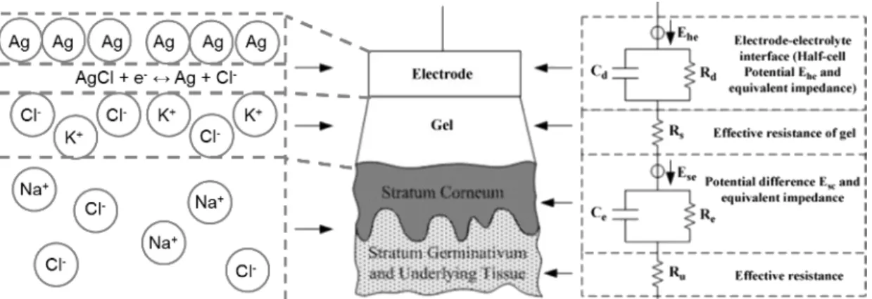
The theory developed in the last years indicate that each component of an entire system, skin (epidermis and dermis) and electrode (electrode plus solution), can be represented with ionic and electric characteristics.
Figure 1.7: Scheme of the layers involved on the interaction electrode-skin. On the left, ionic characteristics. On the right, electronic characteristics [21].
One important point on the electronic representation of an electrode lies on the fact that the impedance changes with the signal frequency which can be caused by the types of materials used and the thickness of the AgCl layer. With low frequencies the impedance should be high and stable (due to the resistor), however from a certain frequency the impedance should decrease due to the capacitive component [20].
1.2.1 Conventional electrodes
Throughout time there has been a concern to optimize the electrodes in a way to perform more reliable measurements and closest to the physiological processes. The better way to improve electrode performance was optimizing the electric properties which can be made in two ways. The first, more intuitive, is decreasing only the resistance value of the equivalent circuit obtaining passive electrodes. The second is increasing both capacitive and resistive component, active electrodes. [21].
The first option of decreasing the resistive component of the entire system is done daily in clinical environment when the standard wet electrodes are used for measuring EMG, ECG or EEG. These electrodes are, typically, disks of a conductor material, usually silver, with the previous mentioned top layer made of silver chloride. Yet, another layer is added: an electrolytic gel. The function of the electrolytic gel is, precisely, minimize the impedance that exists between the electrode system and the skin system (surface plus deeper layers). This gel is a potassium chloride or sodium chloride solution which operates as an intermediate between the electrode and skin, maximizing the contact. However, the great disadvantage of these type of electrodes is that they can not be used for a long period of time [21].
Another type of electrodes are those called active or dry electrodes. These electrodes may be either resistively or capacitively coupled to the skin. This type of electrodes
did not require any type of electrolytic gel as an intermediate therefore the value of the resistive component is greater than the previous ones but have a higher inherent noise level. Unlikely the wet electrodes, dry electrodes are mostly non-polarizable whereas their applications are directed to long term measurements, typically, cardiac measure-ments that expect few chest moves. However, its reliability may decrease because their dielectric properties are susceptible to change with the presence of perspiration and the erosion of the dielectric substance. For these type of electrodes, the materials used to built them are iridium oxide, platinum or aluminium. In an attempt to replace the gel, is sometimes used a spongy and viscous material that serves the same purpose but is not as effective [14]. Most of active electrodes contain a high input impedance electronics amplifier in the same housing as the detection surfaces.
(a) (b)
Figure 1.8: Spiked electrodes. (a) Representative scheme of the spiked electrodes on the skin [22]. (b) SEM photo of the needles of spiked electrodes [23].
Yet, there is another type of electrodes that try to reduce the resistance to improve their performance. The main objective was to abdicate of electrolytic gel, like the dry electrodes, but benefit with the low impedance of the wet electrodes. The solution were the three dimension (3D) or spiked electrodes. This type of electrodes have, as their main advantage, the design. On the surface that have contact with the skin, is placed needles with length enough to achieve the most resistive layer of the skin, the stratum corneum. Typically, these needles have a length of approximately 100 µm, however, is not a standard value neither for every person or every anatomic regions of the same person. This is, obviously a disadvantage because if the needles are too short, the stratum corneum is not overpassed. Nevertheless, if the needles are excessively long, can cause discomfort or even pain [22].
Another options to improve the performance of electrodes are being explored nowadays. Although contradictory, the signals collected by electrodes could be good if the resis-tance on skin-electrode interface is infinite. It was shown that this technique is great for reception of low noise signals. What happens is that this electrodes have a extra capacitive component which allows the collection of physiological signals if the contact
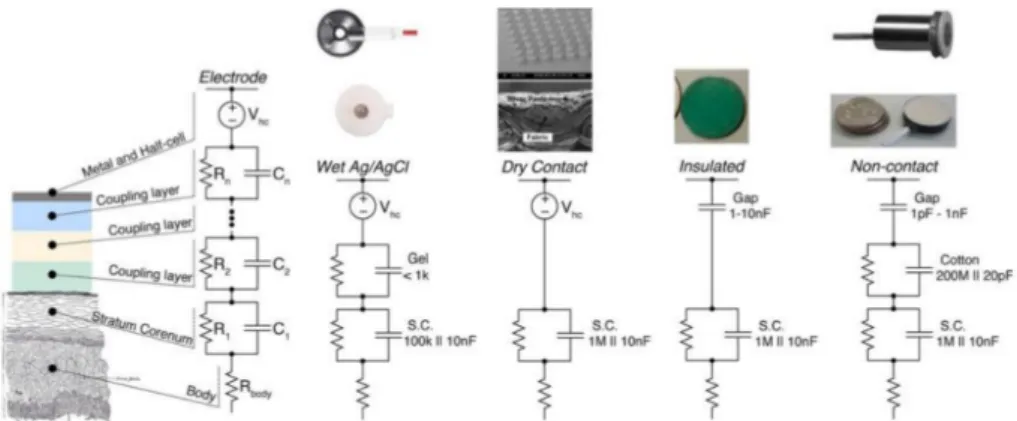
between the electrode and and skin is not consistent or even interrupted. These elec-trodes are, today, commercialize to general public because are incorporated into clothing and sport accessories to keep the athletes monitoring throughout the physical exercise [21]. The electric properties of several type of electrodes are in Figure 1.9.
Figure 1.9: Electric properties of the electrode-skin interface for several types of electrodes including, from right to left, standard wet Ag-AgCl electrodes, dry electrodes,
capacitive electrodes with contact and without contact [21].
Although the diversity of electrodes fabricated and their applications, a lack of using a new approach to obtain new types of electrodes with different physical characteristics, like the concept of electronic skin.
1.3
State-of-Art of non conventional electrodes
The concept of electronic skin started with the idea to integrate electronic devices into substrates with human skin characteristics. The concept was initially developed for robotic applications, an attempt to give the touch capability to hand prostheses using several pressure sensors [24]. However, the applications of the concept could go beyond robotics.
The first group developing the concept of electronic skin [25], created a new approach to the interface between physiological measurements and stimulation and the skin. In order to overtake the most traditional designs and their limitations, they produced a new approach to group electrodes, sensors, electronic components, energy supply and connectivity into thin and flexible membranes.
The device flexibility was achieved, partly, due to substrate selection but also to the serpentine shape of components and sensors. The membrane in which the components are into is kept by two other protective membranes with equal thickness. In order to the device not cause discomfort to the user, the membranes were developed to be thin, light, adaptable and with an adequate adhesion to natural skin [24].
(a) (b)
Figure 1.10: Electronic skin developed by [24]. (a) Scheme of electronic skin with several components on a flexible substrate. (b) The entire system on it normal state in
contact with skin.
The researcher team, [25], has accomplished the integration of multifunctional sensors (such as temperature, strain, and electro physiological) microscale light-emitting diodes (LEDs), active and passive circuit elements (such as transistors, diodes, and resistors), wireless power coils, and devices for radio frequency (RF) communications (such as high-frequency inductors, capacitors, oscillators, and antennae), all integrated on the surface of a thin (∼30 mm), gas-permeable elastomeric sheet based on a modified polyester. The active elements use established electronic materials, such as silicon and gallium arsenide, in the form of curved filamentary. The result is a high-performance system that offers reversible, elastic responses to large strain deformations that are orders of magnitude smaller than those possible with conventional electronics or even with recently explored flexible/stretchable device technologies. These mechanical characteristics lead to robust adhesion to the skin via Van der Waals forces alone, without any mechanical fixturing hardware or adhesive tapes [25].
Electronics in this form were also integrated directly with commercial temporary transfer tattoos as a substrate alternative to polyester or polyvinyl acetate (PVA). The electronic skin was configured for measuring ECG, EMG, and EEG in conformal, skin-mounted modes without conductive gels or penetrating needles providing important, system-level demonstrations. All materials that come into direct contact with the skin (gold, poly-imide, and polyester) are biocompatible. The devices were used for up to 24 hours or more on neck, forehead, cheek and chin and showed no degradation or irritation to the skin. The result of ECG recordings from the chest revealed high-quality signals with information on all phases of the heartbeat, including rapid depolarization of the cardiac wave, and the associated QRS complex [25].
However the fabrication process, transfer printing, of the entire system is quite complex and have several phases. The transfer-printing fabrication approach has proved to be
viable and low-cost in this demonstration, which will greatly facilitate the practical clinical use of the electronic skin. Nevertheless transfer printing is based on molds construction which are made by lithography procedures [26]. Besides, the skin electronic device has flexible transistors for signal amplification so to built this components, was used an additional process similar to the first [27].
For that reason, the use of a simpler technique like inkjet printing to build a complex system as the mentioned could bring some advantages. Many groups have been trying to develop almost the same components on the electronic skin but separately. At least one research group tried to implement electrodes on a flexible substrate using inkjet tech-nology. They reported a high performance and stable inkjet printed stretchable silver electrodes on wave structured elastomeric substrate. They deposited conductive silver directly on a ultraviolet ozone treated polydimethylsiloxane (PDMS) substrates having vertical wavy structures. The ultraviolet ozone treatment and intentionally roughness surface improved adhesion between silver ink and PDMS surface. The group optimized inkjetting conditions to obtain well deposited silver electrodes by controlling the car-tridge temperature, ink drop velocity and drop spacing (resolution) [28].
Figure 1.11: Fabrication process scheme of the inkjet printed stretchable silver elec-trodes by Chung et al. [28].
The group [28] compared the method of printing silver ink on PDMS with and without wavy structure, concluding that the adhesion and stretching performance were much improved when the substrates with wavy structures were introduce. They also concluded that increasing the number of printings, thick and low resistance metal electrodes can be obtained. However, depositing too thick metal films on a compliant substrate typically show poor stretchability. The procedure consisted in roughing intentionally the PDMS by roughing first the aluminium mold with wavy patterns with period and amplitude of 200 µm using a wire-electro discharging machine. Then, two times printed silver electrodes having width 1 mm and length of 20 mm and thickness of 1.6 µm shows sheet resistance of 0.44 Ω/sq after sinterization process at 100◦C on a hot plate during 1h. The inkjet printed stretchable silver electrodes showed good stretchable performance at low to high speed strain stress and good stability [28].
1.4
Electromyography
Electrophysiology is the study of the electrical properties of biological cells and tissues which involves measurements of voltage change or electric current, named biopotentials. The origins of these biopotentials can be traced at the cellular level and the electric potential across a cell membrane is the result of different ionic concentrations that exist inside and outside the cell. The semipermeable membrane separates high concentrations of potassium ion and low concentration of, mostly, sodium ions inside and outside the cell. Some of the cells in the body are excitable and produce an action potential, which results from a rapid flux of ions across the cell membrane in response to an electric stimulation or transient change in the electric gradient of the cell. The electric excitation of cells generates currents in the surrounding volume conductor manifesting itself as potentials in the body.
Many organs in the body such as muscles, heart, brain and eyes manifest their func-tion through electric activity, generating biopotentials capable of being measured. The heart, for instance, produces a signal called electrocardiogram, the brain produces a signal called electroencephalogram, eye movements results in a signal called electroocu-logram and the activity of the muscles, such as contractions and relaxation produces an electromyogram.
Electromyography (EMG) is an experimental technique concerned with the development, recording and analysis of myoelectric signals. It provides easy access to physiological processes that cause the muscle to generate force, produce movement and accomplish the countless functions which allow us to interact with the world around us. The EMG signal is the electrical manifestation of the neuromuscular activation associated with a contracting muscle. The signal represents the current generated by the ionic flow across the membrane of the muscle fibers that propagates through the intervening tissues to reach the detection surface of an electrode located in the environment. It is a complicated signal that is affected by the anatomical and physiological properties of muscles and the control scheme of the nervous system, as well as the characteristics of the instrumentation used to detect and observe it.
In order to understand the EMG signal, it is necessary to appreciate some fundamental aspects of physiology. Muscle fibers are innervated in groups called motor units, which when activated generate a motor unit action potential. The activation from the central nervous system is repeated continuously for as long as the muscle is required to generate force. This continued activation generates motor unit action potential trains. These trains from the concurrently active motor units superimpose to form the EMG signal. As the excitation from the central nervous system increases to generate greater force in
the muscle, a greater number of motor units are recruited and the firing rates of all the active motor units increases.
The most fundamental functional unit of a muscle is called the motor unit. The electrical signal that emanates from the activation of the muscle fibers of a motor unit that are in the detectable surrounding area of an electrode is called the motor unit action potential (MUAP) which constitutes the fundamental unit of the EMG signal. Many factors may influence the shape of the MUAP like:
• the relative geometrical relationship of the detection surfaces of the electrode and the muscles fibers of the motor unit in the surrounding area;
• the relative position of the region where the nerve branches contact the muscle fibers;
• the size of the muscle fibers cause the amplitude of the individual action potential is proportional to the diameter of the fiber;
• the number of muscle fibers of an individual motor unit in the detectable surround-ing area of the electrode.
The last two factors have particular importance in clinical applications to identify phological modifications of the MUAP shape resulting from modifications in the mor-phology of the muscle fibers (hypertrophy and atrophy) or the motor unit (loss of muscle fibers and regeneration of axons). Although usage of MUAP shape analysis is common practice among neurologists, interpretation of the results is not always straightforward and relies heavily on the experience and disposition of the observer.
The electrical manifestation of a MUAP is accompanied by a contractile twitch of the muscle fibers. To sustain a muscle contraction, the motor units must be activated repeatedly. The resulting sequence of MUAPs is called a motor unit action potential train (MUAPT). The waveform of the MUAPs within a MUAPT will remain constant if the geometric relationship between the electrode and the active muscle fibers remains constant, if the properties of the recording electrode do not change, and if there are no significant biochemical changes in the muscle tissue. Biochemical changes within the muscle can affect the conduction velocity of the muscle fiber and the filtering properties of the muscle tissue.
Therefore the final EMG signal is formed by adding several MUAPTs which can be detected by electrodes either located on the surface (skin) or inserted beneath it, using needle or wire electrodes. Both electrodes types can be used singularly (monopolar configurations) or, typically, in pairs (bipolar configuration).
Figure 1.12: Structures responsible for promoting an EMG signal.
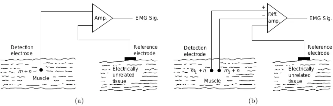
The electrical activity inside a muscle or on the surface of the skin outside a muscle may be easily acquired by placing an electrode with only one detection surface in either en-vironment and detecting the electrical potential at this point with respect to a reference electrode located in an environment that either is electrically quiet or contains electrical signals unrelated to those being detected. Such an arrangement is called monopolar and is at times used in clinical environments because of its relative technical simplicity. This configuration has the drawback that it will detect all the electrical signals in the vicinity of the detection surface which includes unwanted signals from sources other than the muscle of interest.
The bipolar detection configuration overcomes this limitation. In this case, two sur-face electrodes are used to detect two potentials in the muscle tissue of interest each with respect to the reference electrode. The two signals are then fed to a differential amplifier which amplifies the difference of the two signals. Signals emanating from the muscle tissue of interest near the detection surface will be dissimilar at each detection surface because of the localized electrochemical events occurring in the contracting mus-cle fibers, whereas AC noise signals originating from a more distant source (50 or 60 Hz electromagnetic signals radiating from electronic devices) and DC noise signals (polar-ization potentials in the metal electrolyte junction) will be detected with an essentially similar amplitude at both detection surfaces. Therefore, they will be subtracted, but not necessarily nullified prior to being amplified.
EMG provides many important and useful applications, besides basic physiological (anal-ysis of MUAP morphology or screening pathologies like dystrophy and muscle infection) and biomechanical studies (muscular load during a task, ergonomics studies), EMG is established as an evaluation tool for applied research, physiotherapy/rehabilitation, sports training and to generate control commands for human computer interfaces. Con-trol systems based on the classification of EMG signals are used in two main potentials applications: powered upper-limb prostheses and electric powered wheelchairs. Most
(a) (b)
Figure 1.13: EMG detection using (a) monopolar configuration and (b) bipolar con-figuration.
commercial EMG based prostheses recognize the user’s movements by comparing mag-nitude features of EMG signals with a predeterminated threshold generating a small number of control commands.
1.5
Motivation
This thesis attempts to use the several advantages of inkjet printing technology to de-velop devices and applications in biomedical field introducing new designs and features used to acquire EMG signals.
This thesis proposes the use of inkjet printing technology to develop non conventional electrodes for measuring physiological signals, particularly EMG signals introducing the electronic skin concept. The study for the thesis include the entire process of fabrication, optimizing printing conditions to each electrode type; designing studies, to extract the most advantages of each material; material cleaning and handling; visualization and comparison of the printed electrodes to the commercial ones.
From my knowledge, this is the first time that inkjet technology is used to fabricate electrodes for biomedical applications. Despite of the several applications and studies done using inkjet printing, this is the first study that combines the flexibility of the materials to the possibility of printing any conducting pattern to conceive devices to be in contact with the skin and extract physiological information.
Through the development of this thesis several ideas were thought and discussed and have potential to be continued as future work. I believe this is the first step to introduce a low cost and intuitive procedure to fabricate devices with innovative characteristics into biomedical world.
1.6
Outline
Chapter 1 introduces the inkjet printing technology explaining how it operates and advantages when compared with others fabrication techniques. It also includes an intro-duction to electrodes explaining the chemistry and electronics behind the conventional and non conventional electrodes showing the state-of-the-art for those devices. Chap-ter 1 also introduces electromyography, what it is and how can be recorded. Finally, presents the motivation for this work.
Chapter 2 describes the materials and fabrication procedures used to develop printed electrodes. It presents characteristics of each substrate, silver ink nanoparticle and also the designs of electrodes used in this work.
Chapter 3 contains the results of tests performed on printed electrodes. This results includes sheet resistant, resistivity and impedance measurements that allows a charac-terization of printed electrodes. Also contains the performance of printed electrodes in real electromyographic and electrocardiographic measurements.
Chapter 4 describes the methods implemented with MatLab used for post signal acqui-sition. This Chapter includes algorithms for movement detection, features extraction and a classification procedure to distinguish three different movements.
Chapter 5 starts to an introduction of a platform that enables the acquisition of biosig-nals. Then, it describes the fabrication procedures to reproduce some of the circuits presented before.
Chapter 6 makes the final conclusion remarks, presents possible applications for the work developed and discusses future work.
Printed Electrodes
2.1
Materials
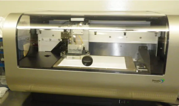
To fabricate printed electrodes was used a drop-on-demand Fujifilm Dimatrix 2831 Ma-terials Printer (DMP-2831) which has a piezoelectric system for controlling the nozzles. DMP-2831 (see Figure 2.1)is a materials deposition system designed for micro-precision jetting, a variety of functional fluids onto several types of surface, including plastic, glass, ceramics, and silicon, as well as flexible substrates from membranes, gels, and thin films to paper products.
Figure 2.1: Fujifilm Dimatrix 2831 Materials Printer.
DMP-2831 is a useful machine that facilitates developing and testing manufacturing processes and product prototypes. The drop-on-demand system minimizes waste of
expensive fluid materials, thereby eliminating the cost and complexity. Besides, DMP-2831 fits within standard flow chamber which is the only lab material required to use it [3].
This printer allows the deposition of fluidic materials on 200 x 300 mm substrates and handles substrates up to 25 mm thick, utilizing a disposable piezoelectric inkjet car-tridge. The temperature of the vacuum platen, which secures the substrate in place, can be adjusted up to 60◦C. A waveform editor and a drop-watch camera system allows manipulation of the electronic pulses to the piezoelectric jetting device for optimization of the drop characteristics as it is ejected from the nozzle. This system enables easy printing of structures and samples for process verification and prototype creation. To minimize waste of expensive fluids, each cartridge reservoir has a capacity of 1.5 ml. Cartridges can easily be replaced to facilitate printing of a series of fluids. Each single-use cartridge has 16 nozzles linearly spaced at 254 microns with typical drop sizes of 10 picoliters. Cartridges with drop volume of 1 pL are also available. The printer’s resolution permits printing any pattern at 5 - 254 µm dot pitch with a repeatability of ±25µm.
2.1.1 Ink
The application of inkjet printing for patterning several devices requires functional inks holding special properties. Different types of inks can be used including organometallic compounds in solution which can be converted to metal at low temperature, conductive polymers and suspensions of nanoparticles using many kind of metals (gold, silver and copper). Those inks typically contain other additives such as dispersants, adhesion promoters, surfactants, thickeners and others [29].
Among metal nanoparticles inks, silver has gained more interest in part due to its price and performance. The finely dispersed silver nanoparticle is gaining comprehensive applications, such as catalyst and active ink for electronics, due to the unique properties of chemical stability, catalytic activity and excellent electric conductivity. For successful application and commercialization, silver nanoparticles dispersion in water inks adopted by inkjet printing technique allows a simple and inexpensive method for nanoparticle preparation, ink formulation with a stable aqueous metal dispersion, and a printed pattern with high electric conductivity. Conductive silver inks which exhibit nearly Newtonian rheological behavior has excellent dispersion stability [4].
In addition to the electrical properties the materials printability plays critical roles in inkjet printing. Firstly, the ink must have the capability of being stable and accurately printed. Secondly, the ink has to meet strict physicochemical properties to achieve
the best printed patterning, optimal performance and reliability. The most important ink’s properties that dictate its printability is fluid properties, namely, viscosity, surface tension and density [5]. Those factors will have a critical role on the size and shape of the deposited droplets and the existence or not of satellite drops. In one hand, the viscosity of the ink must be low enough to enable the refill of the cartridge and the expulsion of a drop out of the nozzle by the transient pressure pulse. In another hand, the surface tension must be high enough to prevent unwanted dripping from the nozzle but low enough such that the ejected droplet can break away from the nozzle. Also, structure at both molecular and nano scale will impact attributes such as morphology (surface roughness, grain size), adhesion, mechanical integrity, solubility, and chemical and environmental stability [4].
To achieve a good printing result, the key characteristics of a piezoelectric inkjet ink are the dynamic viscosity of less than 20 mPa.s, surface tension value below 80 mN.m−1, stability of the ink in solution/suspension in the printhead, and the particle size of the ink constituents preferably much lower, by orders of magnitude, than nozzle orifice. For those reasons, to develop printed electrodes it was used a silver nanoparticle ink from SunTronic in which silver nanoparticles with size of less than 150 nm were dispersed in 20 wt.% of organic solvents (ethanol and ethanediol). This ink has a viscosity of 10 to 13 mPa.s and a surface tension of 28.0 to 31 mN.m−1, both characteristics in the range of values to obtain good printing results.
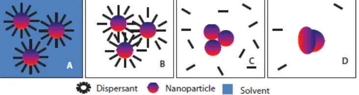
Finally, electric characteristics of this silver ink also depend on the sintering process (see Figure 2.2) because it requires a suitable transformation of the deposited ink layer to render it functional [30]. Sintering promotes a conductive path and grain growth, especially for metal nanoparticle inks which further improves electrical conductivity and mechanical adhesion. For silver nanoparticle ink, is necessary sintering to form connec-tions between neighbour particles for achieving a better conductive film. This approxi-mation of neighbour particles is due to the removal of organic coatings of nanoparticles therefore, at least, is required an application of a temperature capable of removing these organic materials. Although sintering is commonly carried out by heating, other tech-niques can be used, such as electrical, photonic and microwave sintering [29]. These factors, in turn, will affect device performance, notably electrical performance.
SunTronic silver ink used can achieve a volume resistivity of 5 to 30 µΩ.cm after sintering at 150 to 300◦C. However, thermal sintering is not suitable for all types of substrates, as the sintering temperature is between the values mentioned before, many polymer substrates cannot withstand such temperatures. In the electrode development, this temperature was changed for each type of substrate used to exploit the best features of both ink and substrate.
Figure 2.2: Sintering process of nanoparticles silver ink. (A) Nanoparticles dispersed in solvent; (B) solvent is evaporated due to heating; (C) Evaporation of dispersant and
other additives; (D) sintering of nanoparticles [3].
2.1.2 Substrate
As mentioned earlier, inkjet printing itself does not depend on the substrate. It is possible to use a wide type of substrate: rigid, flexible, reinforced and non-reinforced. However, the interaction of the printed ink and the substrate plays a decisive role in determining the accuracy and robustness of the printed structure, and ink properties and substrate properties have to be well matched. As a result, the substrate surface is usually processed prior to printing in order to improve wetting and adhesion. Each substrate used in this work had a specific treatment that was optimized to their intrinsic characteristics.
2.1.2.1 Photographic paper
Paper is probably the cheapest and most widely used flexible substrate in daily life. When compared to plastic substrates such as polyethylene terephtalate (PET), polymide (PI) and others, its price is significantly lower. In addition to this, paper is also environ-mentally friendly and is more available. Recently, it has been considered as a potential substrate for low-cost flexible electronics, which motivate us to create paper electrodes to be used in biosignals acquisition. With this approach, the electrodes can have reduced costs, with potential to produce disposable electrodes.
The paper used as a substrate for printed electrodes is a common photographic paper 230 µm thick. This type of paper is commonly coated with certain compounds that grant qualities to the paper, such as surface smoothness and gloss, weight and inks absorption. Unlike common paper, photographic paper is a good substrate to use for inkjet printing due to its coating layers. Usually, most commercial photographic papers are coated with one or two layers of polyethylene layers making the paper base impermeable to liquids. It is also added a clear resin layer above an emulsion layer which protects it from physical damage. The layers added after the paper base improve dimensional stability, prevents the paper from curling upon drying, reduce drying times and makes the surface very smooth. Those characteristics make photographic paper a good substrate for printing conductive patterns of silver nanoparticles ink.
To perform the ink sinterization after the printing procedure it was necessary to measure the resistance of the photographic paper to high temperatures. A piece of photographic paper was placed on a heating plate and was registered that the maximum tempera-ture that the paper resists is 120◦C. However, to guarantee the non degradation of the photographic paper, the sinterization process was made at a maximum of 100◦C. Before the printing procedure and to ensure the success of it, the surface of photographic paper was clean with a jet of compressed air to remove dust particles.
2.1.2.2 Polydimethylsiloxane
As a substrate for printed electrodes, it was also used the elastomer polydimethylsilox-ane (PDMS), a silicone rubber, which is known to be inexpensive, biocompatible, and amenable to molding micro scale, and to have excellent gas and water permeability [31]. Most polydimethylsiloxane fluids are non-volatile polymeric organosilicon materials con-sisting of (CH3)2SiO structural units (see Figure 2.3), typically more than 4. The poly-mer backbones of polysiloxane is the same as glass like materials. It is the high flexibility around the oxygen atom in the siloxane backbone, and the low intermolecular forces that make the polymers very flexible. In silicone rubbers, organic groups are attached to the silicon atoms and methyl groups are the most abundant. To create silicone rubber, some methyl groups are exchanged with vinyl or phenyl groups which provide rubber like structures that are flexible at extreme low temperatures [32]. It is the cross-linking abilities of the vinyl groups that provide the means to create rubber or solid structures [33].
Figure 2.3: The chemical structure of PDMS with, typically, n¿4 [34].
Recently, the PDMS material is receiving increasing amount of attention from researchers from several activities, including microelectromechanical systems fabrication. The major advantages of this polymeric compound relies on its mechanical and chemical proper-ties. Since PDMS is viscoelastic, it acts like a viscous liquid when is prepared and could cover any surface and mold to it and acts like an elastic solid similar to rubber after a curing process. The final form of the cured PDMS has a stabilized cross structure, which is non-soluble and stable at higher temperatures [35]. It is also transparent at least within the visible spectrum which can be used to monitor, for instance, fluid flow inside it. Besides, the chemical stability translates on interesting and strong mechanical
![Figure 1.2: Schematic diagram of a single-jet of continuous inkjet printer [8].](https://thumb-eu.123doks.com/thumbv2/123dok_br/19184114.946764/18.893.339.601.477.651/figure-schematic-diagram-single-jet-continuous-inkjet-printer.webp)
![Figure 1.6: Scheme of an ink drop behaviour in contact with (a) a hydrophilic surface and (b) extremelly hidrophobic surface [11].](https://thumb-eu.123doks.com/thumbv2/123dok_br/19184114.946764/23.893.281.672.125.290/figure-scheme-behaviour-contact-hydrophilic-surface-extremelly-hidrophobic.webp)
![Figure 1.8: Spiked electrodes. (a) Representative scheme of the spiked electrodes on the skin [22]](https://thumb-eu.123doks.com/thumbv2/123dok_br/19184114.946764/26.893.223.723.426.636/figure-spiked-electrodes-representative-scheme-spiked-electrodes-skin.webp)
![Figure 1.10: Electronic skin developed by [24]. (a) Scheme of electronic skin with several components on a flexible substrate](https://thumb-eu.123doks.com/thumbv2/123dok_br/19184114.946764/28.893.173.780.124.365/figure-electronic-developed-scheme-electronic-components-flexible-substrate.webp)