Article
Printed in Brazil - ©2017 Sociedade Brasileira de Química 0103 - 5053 $6.00+0.00
*e-mail: [email protected]
Nickel-Copper Alloys Modified Electrodes: an Electrochemical Study on
their Interfacial and Supercapacitive Properties
Franciele Wolfart,a Bianca R. Brito,a Luís F. Marchesia,b and Marcio Vidotti*,a
aGrupo de Pesquisa em Macromoléculas e Interfaces, Departamento de Química,
Universidade Federal do Paraná, CP 19032, 81531-980 Curitiba-PR, Brazil
bUniversidade Tecnológica Federal do Paraná, Av. Monteiro Lobato, s/n, km 04,
84016-210 Ponta Grossa-PR, Brazil
In this manuscript, we report the electrodeposition of nickel-copper alloys in a two steps methodology. Firstly, the copper electrode is oxidized to generate Cu2+ ions followed by the reduction of both Ni2+ and Cu2+. The electrodes were further cycled in KOH to convert the metallic alloy into the respective electroactive hydroxide. This methodology created an electrode with high roughness and distinct electrochemical behavior. The modified electrodes were also characterized by electrochemical impedance spectroscopy (EIS) and scanning electron microscopy (SEM). Finally, the modified electrodes were studied in their supercapacitive properties by galvanostatic charge and discharge curves; the electrodes showed a good specific capacitance of 58 mF cm-2. The results indicated a new strategy using a simple methodology to modified Cu-electrodes to develop supercapacitors at low cost.
Keywords: nickel-copper hydroxides, supercapacitors, electrodeposition, interfacial properties
Introduction
Nowadays, the worldwide demand for energy impacts the research in new energy storage and conversion devices where it is intended an enhanced efficiency, low-cost and eco-friendly alternative.1-3 Among them, supercapacitors (SCs) arise as a
good alternative due to their ease-preparation, long cycle life and fast and reversible redox reactions.4-6 Supercapacitors,
ultracapacitors or electrochemical capacitors are devices that combine the power delivery presented in the capacitors and the energy density presented by the batteries.7 Based
on the charge storage mechanism, supercapacitors can be divided into two categories: electrochemical double-layer capacitors (EDLCs), where the capacitance arises from the charge accumulated at the electrode/electrolyte interface. Carbonaceous materials such as graphene and carbon nanotubes are typical examples vastly employed in EDLCs.8,9 The second one are the pseudocapacitors,
which the charge storage mechanism is based on both double layer capacitance and fast redox reactions at the electrode/electrolyte interface, increasing the overall density of current produced. Typical pseudocapacitors
materials are transition metals oxide/hydroxide (TMOH) and conducting polymers.10-12
Amongst the different TMOH used as supercapacitors electrodes, RuO2 is by far one of the most investigated
material due to its high theoretical specific capacitance, long cycle life and rate capability, electrochemical properties and conductivity.13 However, its high-cost
and scarcity is the main drawback related to RuO2 based
materials in commercial devices. In this way, in order to obtain more attractive materials, TMOH alloys based on low-cost metals have been extensively studied.14
Shinde et al.15 studied the incorporation of Mn in
CuO/Cu(OH)2 by successive ionic layer adsorption and
reaction (SILAR) technique. The authors have found an improved specific capacitance of 600 F g-1 for the doped
material that was ascribed to a change in the morphology occasioned by the Mn doping effect.
Another TMOH of interest is the versatile Ni(OH)2.
This material presents many different applications, such as sensors, electrochromic electrodes, batteries, etc.16
and it is well reported in the supercapacitor technology.17
However, although Ni(OH)2 is a promising material to
cycle stability is the main drawback to be overcome.18 An
alternative is to synthesize compounds based on mixed metals, adding a foreign atom in the nickel hydroxide structure.19,20 Zheng et al.21 studied a nickel-copper
carbonate hydroxide hierarchical nanowire network electrode and found a specific capacitance of 971 F g-1, an
excellent long-life cycling stability and a retention capacity of 91.5% after 2000 cycles. Hierarchical Co3O4@Ni-Co-O
nanosheet-nanorod arrays was developed with high specific capacitance 25 F cm-2 retaining ca. 96% after 1000 cycles,
indicating that the charge and discharge processes did not induce significant structural change in the electrode.19
It is well known that the electrode morphology plays an important role in the supercapacitor performance, to guarantee fast redox reactions at the electrode/electrolyte interface an intimate contact between them is desired.22,23
By this way, the electrode modification by the active material is a fundamental step to be analyzed. The simplest methodology can be described in terms of electrodeposition of electroactive materials. These methods are largely used to obtain different morphology and composites of transition metals. The facility on the fabrication, environmentally friendly and scalable at low cost advantages makes this technique very interesting in both academic and industry researches.24 Manganese oxide nanotubes are
electrosynthesized by the cyclic voltammetric method. The easy and economical method of synthesis make this material useful for field-emission applications.25
Three-dimensional nanostructures of β-Co(OH)2 were
synthesized by one-step electrodeposition process using a simple two-electrode system.26 By controlling the time of
the voltage applied, the nanostructures were self-assembled from nanoplates to multilayered nanoplates building blocks showing higher specific capacitance values.26
Macroporous manganese oxide electrodes were prepared by template-assisted electrodeposition showing specific capacitance 60% higher than that obtained from flat surfaces, without loss of capacitance even after 1000 cycles.27 In addition, Tsai et al.28 reported the influence
of the electrodeposition method on the morphology and capacitive properties of the electrodes. In this work, it was described the preparation of composites based on MnO2/Ni
foams by three different methods: potentiodynamic (PD), potentiostatic (PS) and a combination of them (PS + PD). The MnO2/Ni electrodes obtained by (PS + PD) methodology
showed higher specific area (103 m2 g-1) if compared
with the electrodes prepared by PD (21 m2 g-1) and PS
(86 m2 g-1) methods. The highly-porous structure of the
(PS + PD) MnO2/Ni foams electrodes provides abundant
space to the electrolyte transport into the electrode material resulting in excellent electrochemical performance.28
Also, Ni-Co double hydroxide nanocomposite were electrodeposited on porous NiCo2O4 nanowires previously
grown on carbon fiber paper. The composites electrodes showed high specific capacitance (1.64 F cm-2) and long
cycle life.29 In other contribution, the direct electrodeposition
of nickel alloys was described and characterized in terms of their electrocatalytical properties.30,31
A s d e s c r i b e d a b ove t h e a d va n t a g e s o f t h e electrodeposition technique are very promising in the development of low cost materials in high scale and holds great potential for miniaturization of electrochemical devices. In this contribution, we describe a simple and direct electrodepositon of Ni-Cu alloys directly onto low-cost copper electrodes. The modified electrodes were characterized by electrochemical techniques and by scanning electron microscopy (SEM). The electroactive interface obtained was deeply investigated in the construction of a high-performance electrode aiming the development of supercapacitors.
Experimental
Ni(SO4)2, KOH and KCl were obtained from Synth. The
formation of NiCu metallic alloys onto copper electrodes followed the following steps: initially, in a Ni(SO4)2
solution (10 mmol L-1) it was applied an oxidative potential
(E1 = 0.7 V during 50 seconds) at the bare copper electrode
(A = 0.125 cm-2) in order to remove Cu2+ ions from the
electrode surface, then a reducing potential of –1.1 V (during different times) was applied for the co-precipitation of metallic NiCu at the electrode surface. The conversion of metallic NiCu to the oxide/hydroxide form was done by cyclic voltammetry in KOH 1 mol L-1 at 20 mV s-1.
The electrochemical characterization was done in a IVIUM PGStat potentiostat. The cyclic voltammetry was studied between 0.1 and 0.65 V at different scan rates (5, 10, 20, 40, 60, 80 and 100 mV s-1) in KOH 1 mol L-1.
The galvanostatic charge and discharge (GCD) tests were performed between 0.08 and 0.53 V at different current densities (0.1, 0.2, 0.4, 0.6, 0.8 and 1 mA cm-2)
in KOH 1 mol L-1. The electrochemical impedance
spectroscopic data (EIS) were obtained at 0.1 V between 10 kHz to 10 Hz and the ZView program was used to fit the experimental results. All electrochemical experiments were obtained in systems of the three-electrode cell using a large area platinum wire and Ag/AgCl/Cl–
sat
Results and Discussion
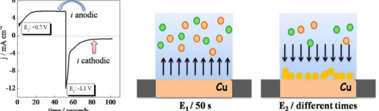
Initially, the copper electrode was submitted to different potential steps in 0.01 mol L-1 Ni(SO
4)2 electrolyte as
described in the Experimental section. The first step occurs when applying a potential of 0.7 V (E1) for 50 seconds, to
increase the electrode roughness and remove Cu2+ from the
electrode surface. The second step is the co-precipitation of both Cu2+ and Ni2+ into the metallic alloy by applying
–1.1 V. This potential is negative enough to perform the random co-deposition providing the morphological change at the electrode surface. The amperometric profile is shown in Figure 1, where it is possible to observe the intense anodic current indicating the continuous oxidation of the electrode to Cu2+ until the drastic change in the current
direction in a diffusional like behavior, corroborating the reduction of ions from the bulk electrolyte. All depositions presented the same behavior regardless the time of deposition or electrolyte employed.
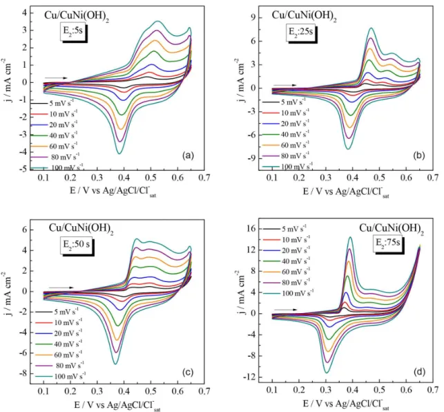
After the alloy formation, the next step is the conversion into the electroactive hydroxide. To do so, the modified electrodes were cycled in KOH 1.0 mol L-1. In Figure 2 are
shown the cyclic voltammograms of the copper electrodes modified by the stripping time of 50 seconds and different reduction times (E2), in absence and presence of 10 mmol L-1
of Ni2+. It is important to mention that as reported elsewhere30
the first cycles of conversion have a different voltammetric shape reaching the stabilization after few cycles.
In the NiCu alloys, in all electrodes we can observe the presence of two oxidation process with a unique reduction wave, as longer the alloy formation (by applying different times of E2) the higher the intensity of the first oxidation
wave presents. Also, there is a clear shifting of the oxidation wave indicating that the Cu/NiCu(OH)2 formed becomes
more conductive material, as observed elsewhere when Co2+ is used as additive.23,31 The second oxidation process
could be attributed to another crystallographic form of the alloy hydroxide, most similar to β-Ni(OH)2 probably with
less amount of Cu2+ in the composite. Another experimental
data that supports this point is the appearance of the intense oxidation process at higher applied potentials ascribed to the O2 reaction, typically catalyzed by the β-Ni(OH)2.32
Also, at different scan rates the voltammetry cyclics (CVs) present a very discrete peak shifting towards more positive potentials, probably related to the internal resistance of the modified electrodes33 but the electrodes present an excellent
reversibility, this fact can be attributed to the very rough surfaces, facilitating the ionic intercalation upon redox reactions.34
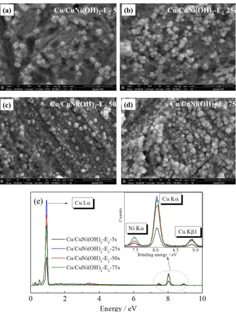
In Figure 3 are shown the SEM images and the EDS spectra of the modified electrodes. Regardless the time of the alloy deposition, there is no apparent change in the size or form of the electrodeposited crystals, instead, a huge increase in the superficial roughness due to the increment of the crystals with the deposition time. It is not evident the precipitation of nanostructures of different morphologies, indicating the Cu/NiCu(OH)2 composite formation. The
SEM images by this way presented a highly electroactive surface, which is the main characteristic for any high performance electrochemical device.
The EDS analysis corroborated the presence of Ni in all modified Cu-electrode (Figure 3e), confirming that the structures observed in the SEM are in fact composites and not Cu(OH)2 itself. At this point, it is important to mention
that due to the low amount of electroactive material on the electrode surface, it was not possible to obtain accurately the real proportions of nickel and copper presented in the composite material, though all the experiments were very reproducible in the very same conditions tested. Although, the electrode modified with 5 s of E2 showed
no peak of Ni in the EDS spectrum, the characteristic redox peak of NiII(OH)
2/NiIIIOOH is clearly present in the
capacitance-voltage curves (Figure 2b) and in the SEM image (Figure 3a), confirming the presence of the Ni in the material. The absence of the Ni peak in the EDS spectrum can be attributed to the low time of E2, resulting in very
Figure 1. Amperometric profile of the electrode modification in Ni(SO4)2 0.01 mol L-1 solution. Also, the scheme of the copper electrode modification is
small amount of Ni in the Cu-electrode surface, in Figure 3a is possible to observe that the electrode is not completely covered with the composite nanostructure where large areas of unmodified copper are observed.
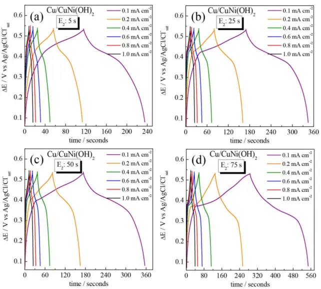
The SEM images and voltammetric results have shown modified electrodes with a large electroactive area and redox reversible behavior, resulting in charge accumulation characteristic of the pseudocapacitive materials. By this way, these modified electrodes can be effectively employed as active material in a supercapacitor device, where a fast and reversible intercalation process is very desirable. The pseudocapacitive experiments were performed in terms of the galvanostatic charge and discharge curves (GCDC) and the results are shown in Figure 4.
The GCDC measurements were performed to further evaluate the electrochemical performance of the electrodes regarding the supercapacitive properties (Figure 4). It is possible to observe an almost symmetrical non-linear
GCDC for all modified electrodes, indicating a good reversibility upon the redox process, as also depicted by the CV results, and the pseudocapacitance behavior.35 It
was also observed that an increase in the current density provokes a diminishment of the discharge time. In this way, the areal specific capacitance (CS) of the modified
electrodes were calculated accordingly to equation 1, as described elsewhere.36,37
(1)
where CS is the areal specific capacitance (mF cm-2), Iis
the applied current (mA cm-2), t
Dis the discharge time (s),
∆V is the potential range (V). It is important to mention that there are many different methodologies to calculate CS found in literature, which might be difficult to compare
the results. Nevertheless, our results can be readily Figure 2. Cyclic voltammetry curves at various scan rate from 5-100 mV s-1 of Cu/NiCu(OH)
2 electrodes at different times of E2: (a) 5 s; (b) 25 s; (c) 50 s;
compared among them, pointing out the differences in the methodology of the electrode modification, which is the key factor of the present manuscript.
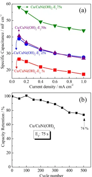
The CS calculated values for an applied current density
of 0.1 mA cm-2 were 27, 39, 41 and 58 mF cm-2 for the
times of deposition of 5, 25, 50 and 75 s, respectively. The highest CS value presented by the 75s-modified
electrode can be explained by the higher amount of the Ni deposited in this electrode increasing the number of intercalation sites. Although the values found to CS were
not so high as others works concerning Ni/Cu hydroxides, important features must be emphasized such as the simple and fast methodology and the low amount of electroactive material electrodeposited which guarantee the low cost for the electrode development using larger scales. Works published about Ni/Cu electrodes can be cited, such as
Ni(OH)2-Cu/nickel foam electrodes presenting specific
capacitance of 8.66 F cm-2 at 1 mA cm-2 in KOH 2 mol L-1.37
This higher value compared to ours can be attributed to the Cu network interwoven in the active material, providing a favorable electron-transport pathway and improve the conductivity of the electrode.37 However, the total time
necessary to prepare the electrodes is around 17 hours with higher amount of material, while the electrodes presented herein can be build up in few minutes. Also, highly laborious multi-step copper modified electrodes such as CuO@layered double hydroxide core-shell nanoarrays presented higher values of CS of about 694, 755 and 866 mF cm-2 for
CuO, CoFe-LDH and CuO@CoFe-LDH, respectively.38
Furthermore, Ni-Cu foams were electrodeposited onto stainless steel electrode by galvanostatic method.38 This
technique is similar with our method in terms of both, fast Figure 3. Representative SEM images obtained directly on the Cu-electrode surface modified with CuNi(OH)2 at different time of E2 application (a) 5 s;
and simple method to obtain of the electrodes, however, the specific capacitance was determined in terms of the mass of the electrode (105 F g-1 at 1 mA cm-2)38 making difficult
the comparison of the values.
The Figure 5 shows the dependence of the CS on the
applied current density for all modified electrodes. The increase of the current density provokes the diminishment of the CS values due to the diffusional process limitation
where some electroactive sites are less available in faster charge intercalation.39 To verify the long-term stability, the
capacity retention was measured as shown in Figure 5b during 500 continuous cycling, applying 0.8 mA cm-2,
which is a higher current if compared with the best CS
value found intending an accelerate durability test. For this experiment the electrode modified during 75 s of alloy deposition. It can be observed a decrease in the CS values
with the number of cycles reaching 74% of the initial value after cycling, in agreement with similar works published elsewhere.15,40,41 Taking into account the higher current
used for this experiment, the electrode presented a good durability.Many different aspects can be attributed to this behavior such as the loss of the material conductivity, the change in the morphology or the dissolution and detachment of the active material from the electrode surface.42-44
To better understand the interfacial properties of the Cu/NiCu(OH)2 modified electrodes, electrochemical
impedance spectroscopy (EIS) measurements were performed. The Nyquist plots are presented in Figure 6 where can be observed a typical EIS response concerning supercapacitors,45,46 i.e., a semicircle at the high-frequency
region (inset), related to the Faradaic process, and a straight line at the low-frequency region, related to the load of intercalated charge within the film in order to maintain the charge neutrality upon oxidation process.47,48
The EIS responses were very similar, by this way, the equivalent circuit modeling was used in order to improve the discussion, as depicted in the Figure 6 and was also considered elsewhere in the interpretation of other modified Figure 4. Galvanostatic charge and discharge curves at different current densities from 0.1 up to 1 mA cm-2 of Cu/NiCu(OH)
2 electrodes. Cu/Ni(OH)2
electrodes49,50 where R
s is the series resistance, accounting
for the contacts and electrolyte resistances, Qdl is a constant
phase element related to the double-layer capacitance, Rct is the charge-transfer resistance that accounts for the
Faradaic process at the electrode/electrolyte interface, and the Qlf element, which is another constant phase element,
relating the low-frequency capacitance and so the quantity of intercalated charge within the film in order to maintain charge neutrality. The fitting results are summarized in Table 1.
At this point, it is very important to mention that the Qdl
values can be directly linked with the EDLC properties, as such parameters concern the electrode/electrolyte interface, on the other hand, the pseudocapacitive properties can be compared with the Qlf values, as these parameters
are related with the intercalated ions. In this way, the best supercapacitive properties accordingly to the EIS results is electrode modified by 75 s of alloy deposition (higher Qdl and Qlf), presenting the larger electrode/
electrolyte interface area and the higher number of intercalated ions, corroborating the GCDC results. Also it is important to mention that the Rs and Rct values do not
present considerable differences between the modified electrodes, supporting the discussion presented herein, by comparing the CS obtained from the GCDC curves and the
EIS results.51,52
Conclusions
In summary, Cu/NiCu(OH)2 modified electrodes were
successfully prepared by a simple and straight forward methodology based on the oxidation of Cu2+ ions from the
copper electrode followed by the coprecipitation of NiCu alloys by applying a reducing potential. Different times of deposition were tested creating different electroactive surfaces with increased roughness as observed by SEM and electrochemical experiments. The high electroactive area of the modified electrodes facilitates the ionic diffusion through the hydroxide matrix, improving the Figure 5. (a) Variation of specific capacitance with current density for all
electrodes in KOH 1 mol L-1; (b) capacity retention of the 75 s modified
electrode in an applied current density of 0.8 mA cm-2.
Figure 6. Nyquist plot at 0.1 V of the Cu/NiCu(OH)2 modified electrodes
obtained from different times of E2 alloy electrodeposition. Electrolyte
KOH 1 mol L-1.
Table 1. EIS related parameters calculated from the results presented in Figure 6 using the equivalent circuit model presented, R > 0.998, RS: series
resistance, Rct: charge-transfer resistance, Qdl: double-layer constant phase
element and Qlf: low-frequency capacitance phase element
time / s RS / Ω Rct / Ω Qdl / (µF sn-1) Qlf / (µF sn-1)
5 7.18 66.8 97.2 139.5
25 7.50 45.7 60.2 210.2
50 6.99 54.1 62.7 178.9
pseudocapacitive behavior. Specific capacitances of about 58 mF cm-2 were found; these values showed good
agreement with the study of the EIS experiments in terms of both double layer capacitance and accumulated charges on the electroactive material. Finally, this work provides a good perspective to obtain energy storage devices employing low cost materials and simple methodologies.
Acknowledgments
The authors thank Brazilian agencies Fundação Araucária (308/2014) CAPES and CNPq (No. 473425/2014-0) for the financial support and Centro de Microscopia Eletrônica da UFPR (CME-UFPR) for the SEM and EDS facilities.
References
1. Jiang, L. L; Cong, S.; Lou, Y.-H.; Yi, Q.-H.; Zhu, J.-T.; Ma, H.; Zou, G.-F.; J. Mater. Chem. A 2016, 4, 217.
2. Li, S.; Zhang, H.; Zhao, W.; Ye, L.; Yao, H.; Yang, B.; Zhang, S.; Hou, J.; Adv. Energy Mater. 2015, 6, 1501991.
3. Dyatkin, B.; Presser, V.; Heon, M.; Lukatskaya, M. R.; Beidaghi, M.; Gogotsi, Y.; ChemSusChem 2013, 6, 2269.
4. Peng, Z.; Guo, Z.; Chu, W.; Wei, M.; RSC Adv. 2016, 6, 42019. 5. Zhao, K.; Liu, S.; Wu, Y.; Lv, K.; Yuan, H.; He, Z.; Electrochim.
Acta 2015, 174, 1234.
6. Ferreira, C. S.; Passos, R. R.; Pocrifka, L. A.; J. Power Sources
2015, 271, 104.
7. Simon, P.; Gogotsi, Y.; Dunn, B.; Science 2014, 343, 1210. 8. Zhan, C.; Neal, J.; Wu, J.; Jiang, D. En.; J. Phys. Chem. C 2015,
119, 22297.
9. Rangom, Y.; Tang, X. S.; Nazar, L. F.; ACS Nano 2015, 9, 7248. 10. Long, X.; Wang, Z.; Xiao, S.; An, Y.; Yang, S.; Mater. Today
2016, 19, 213.
11. Huang, M.; Li, F.; Dong, F.; Zhang, Y. X.; Zhang, L. L.; J. Mater. Chem. A 2015, 3, 21380.
12. Feng, X.; Chan, N.; Zhou, J.; Li, Y.; Huang, Z.; Zhang, L.; Ma, Y.; Wang, L.; Yan, X.; New J. Chem. 2015, 39, 2261. 13. Shi, F.; Li, L.; Wang, X.; Gu, C.; Tu, J.; RSC Adv. 2014, 4,
41910.
14. Ozkale, B.; Mushtaq, F.; Fornell, J.; Chatzipirpiridis, G.; Martin, L. H. J.; Sort, J.; Mueller, C. M.; Pellicer, E.; Nelson, B. J.; Pane, S.; Electrochim. Acta 2016, 204, 199.
15. Shinde, S. K.; Dubal, D. P.; Ghodake, G. S.; Gomez-Romero, P.; Kim, S.; Fulari, V. J.; RSC Adv. 2015, 5, 30478.
16. Vidotti, M.; Torresi, R.; Torresi, S. I. C.; Quim. Nova 2010, 33, 2176.
17. Sk, M. M.; Yue, C. Y.; Ghosh, K.; Jena, R. K.; J. Power Sources
2016, 308, 121.
18. Dubal, D. P.; Gomez-Romero, P.; Sankapal, B. R.; Holze, H.;
Nano Energy2015, 11, 377.
19. Lu, Z.; Yang, Q.; Zhu, W.; Chang, Z.; Liu, J.; Sun, X.; Evans, D. G.; Duan, X.; Nano Res. 2012, 5, 369.
20. Ning, X.; Wang, X.; Yu, X.; Zhao, J.; Wang, M.; Li, H.; Yang, Y.; Sci. Rep. 2016, 6, 22634.
21. Zheng, X; Ye, Y.; Yang, Q.; Geng, B.; Zhang, X.; Chem. Eng. J. 2016,290, 353.
22. Dubal, D. P.; Chodankar, N. R.; Gund, G. S.; Holze, R.; Lokhande, C. D.; Gomez-Romero, P.; Energy Technol. 2015,
3,168.
23. Soares, A. L.; Marchesi, L. F.; Vidotti, M.; Electrochim. Acta
2016, 196, 670.
24. Ribeaucourt, L.; Savidand, G.; Lincot, D.; Chassaing, E.;
Electrochim. Acta 2011, 56, 6628.
25. Wu, M. S.; Lee, J. T.; Wang, Y. Y.; Wan, C. C.; J. Phys. Chem. B
2004, 108, 16331.
26. Nagaraju, G.; Ko, I. H.; Yu, J. S.; CrystEngComm. 2014,16, 11027.
27. Benedetti, T. M.; Gonçales, V. R.; Petri, D. F. S.; Torresi, S. I. C.; Torresi, R. M.; J. Braz. Chem. Soc.2010, 21, 1704. 28. Tsai, Y. C.; Yang, W. D.; Lee, K. C.; Hua, C. M.; Materials
2016,9, 246.
29. Huang, L.; Chen, D.; Ding, Y.; Feng, S.; Wang, Z. L.; Liu, M.;
Nano Lett. 2013, 13, 3135.
30. Wolfart, F.; Maciel, A.; Nagata, N.; Vidotti, M.; J. Solid State Electrochem. 2013, 17, 1333.
31. Wolfart, F.; Lorenzen, A. L.; Nagata, N.; Vidotti, M.; Sens. Actuators, B2013, 186, 528.
32. Yeo, B., S.; Bell, A. T.; J. Phys. Chem. C 2012, 116, 8394. 33. Kuang, M.; Wen, Z. Q.; Guo, X. L.; Zhang, S. M.; Zhang, Y.
X.; J. Power Sources 2014, 270, 426.
34. Deshmukh, P. R.; Bulakhe, R. N.; Pusawale, S. N.; Sartale, S. D.; Lokhande, C. D.; RSC Adv. 2015, 5, 28687.
35. Pedrós, J.; Boscá, A.; Martínez, J.; Ruiz-Gómez, S.; Pérez, L.; Barranco, V.; Calle, F.; J. Power Sources 2016, 317, 35. 36. Shi, D.; Zhang, L.; Yin, X.; Huang, T. J.; Gong, H.; J. Mater.
Chem. A2016, 4,12144.
37. Eugénio, S.; Silva, T. M.; Carmezim, M. J.; Duarte, R. G.; Montemor, M. F.; J. Appl. Electrochem.2014,44,455. 38. Li, Z.; Li, Z.; Shao, M.; Zhou, L.; Zhang, R.; Zhang, C.; Han, J.;
Wei, M.; Evans, D. G.; Duan, X.; Nano Energy 2016, 20, 294.
39. Kim, B. K.; Sy, S.; Yu, A.; Zhang, J.; Handbook of Clean Energy Systems-Electrochemical Supercapacitors for Energy
Storage and Conversion; John Wiley & Sons, Ltd., 2015, DOI:
10.1002/9781118991978.hces112.
40. Lu, Z.; Chang, Z.; Liu, J.; Sun, X.; Nano Res. 2011, 4, 658. 41. Huang, L.; Chen, D.; Ding, Y.; Feng, S.; Wang, Z. L.; Liu, M.;
Nano Lett. 2013, 13, 3135.
42. Sekar, P.; Anothumakkool, B.; Kurungot, S.; ACS Appl. Mater. Interfaces 2015, 7, 7661.
44. Xu, X.; Wang, Q.; Zhang, W.; Wang, Y.; Chen, W.; Electrochim. Acta 2016, 211, 1066.
45. Lin, H.; Huang, Q.; Wang, J.; Jiang, J.; Liu, F.; Chen, Y.; Wang, C.; Lu, D.; Han, S.; Electrochim. Acta 2016, 191, 444. 46. Wolfart, F.; Dubal, D. P.; Vidotti, M.; Gómez-Romero, P.; RSC
Adv. 2016, 6, 15062.
47. Marchesi, L. F.; Jacumasso, S. C.; Quintanilha, R. C.; Winnischofer, H.; Vidotti, M.; Electrochim. Acta 2015, 174, 864.
48. Marchesi, L. F.; Pereira, E. C.; Synth. Met. 2014, 194, 82.
49. Hostert, L.; Alvarenga, G.; Vidotti, M.; Marchesi, L. F.;
J. Electroanal. Chem. 2016, 774, 31.
50. Hostert, L.; Alvarenga, G.; Marchesi, L. F.; Soares, A. L.; Vidotti, M.; Electrochim. Acta 2016, 213, 822.
51. Xie, Y.; Xia, C.; Du, H.; Wang, W.; J. Power Sources 2015, 286, 561.
52. Tayel, M. B.; Soliman, M. M.; Ebrahim, S.; Harb, M. E.; Synth. Met. 2016, 217, 237.
Submitted: October 13, 2016