Universidade do Minho
Escola de EngenhariaTiago João Silva Sousa Azevedo Costa
Analysis of internal combustion engines
towards the improvement of its efficiency
Tese de Mestrado
Ciclo de Estudos Integrados Conducentes ao
Grau de Mestre em Engenharia Mecânica
Trabalho efetuado sob a orientação do
Professor Doutor Jorge José Gomes Martins
Coorientação do
Professor Doutor Francisco Brito
Anexo 3
DECLARAÇÃO
Nome
Endereço electrónico: Telefone:
Número do Bilhete de Identidade: Título dissertação n/tese •
Orientador(es):
Ano de conclusão: Designação do Mestrado ou do Ramo de Conhecimento do Doutoramento:
Nos exemplares das teses de doutoramento ou de mestrado ou de outros trabalhos entregues para prestação de provas públicas nas universidades ou outros estabelecimentos de ensino, e dos quais é obrigatoriamente enviado um exemplar para depósito legal na Biblioteca Nacional e, pelo menos outro para a biblioteca da universidade respectiva, deve constar uma das seguintes declarações:
1. É AUTORIZADA A REPRODUÇÃO INTEGRAL DESTA TESE/TRABALHO APENAS PARA EFEITOS DE INVESTIGAÇÃO, MEDIANTE DECLARAÇÃO ESCRITA DO INTERESSADO, QUE A TAL SE COMPROMETE;
2. É AUTORIZADA A REPRODUÇÃO PARCIAL DESTA TESE/TRABALHO (indicar, caso tal seja necessário, n" máximo de páginas, ilustrações, gráficos, e t c ) , APENAS PARA EFEITOS DE INVESTIGAÇÃO, , MEDIANTE DECLARAÇÃO ESCRITA DO INTERESSADO, QUE A TAL SE COMPROMETE;
3. DE ACORDO COM A LEGISLAÇÃO EM VIGOR, NÃO É PERMITIDA A REPRODUÇÃO DE QUALQUER PARTE DESTA TESE/TRABALHO
Universidade do Minho,
Assinatura:
Tiago João Silva Sousa Azevedo Costa
[email protected] 919030668
13913590
Analysis of Internal Combustion Engines towards the improvement of its efficiency
Professor Doutor Jorge Martins e Professor Doutor Francisco Brito
2014 Mestrado Integrado em Engenharia Mecânica
iii Acknowledgements
The author wishes to thank the following persons for their support during all the work herein described:
Jorge Martins, PhD Francisco Brito, PhD Bernie Bon
iv
Analysis of internal combustion engines towards the improvement of its efficiency Abstract
This work discusses ways for internal combustion engine efficiency improvement using unconventional technologies and mechanisms. A low consumption engine developed to participate in the Eco-Marathon Shell contest was used as a basis for this study.
The first part of this work details the steps of the design and thermodynamic analysis of a high efficient internal combustion engine, with special emphasis on the crankshaft system. The second part analyses the inlet port to enhance production of turbulence by swirl, creating high combustion speeds. To perform this task the use of two software programs was required, SolidWorks, and CONVERGE. The modelling tests included normal engine cycle operation, performing all 4 strokes. An unconventional crankshaft was studied to improve combustion efficiency. The main goal was to generate constant volume combustion to increase combustion efficiency and eliminate negative work done over the piston before top dead centre. CONVERGE, which includes the combustion model SAGE, was used to determinate the heat release rate during constant volume combustion. The purpose of the third part of this work was to calculate the potential for heat recovery of the combustion chamber and exhaust valve walls in order to run the engine as “quasi-adiabatic”, by using a direct water injection added (to cool down the wall surface) after the end of combustion. Finally, all the results of the features were analysed, presented, illustrated and compared using the engine cycle P-V diagram, which clearly shows the overall amount of work produced by the thermodynamic cycle performed with the internal combustion engine. Although more work and study has to be done in order to quantify all the variables involved to produce the most efficient cycle, it is expected that the thermal efficiency might reach values close to 50%.
v Análise de motores de combustão interna para a melhoria da sua eficiência
Resumo
Este trabalho discute formas de melhorar a eficiência de motores de combustão interna, utilizando tecnologias e mecanismos não convencionais. Um motor de baixo consumo desenvolvido para participar na competição Eco-Marathon Shell foi utilizado como base para o presente estudo. A primeira parte deste trabalho detalha as etapas de projeto e análise termodinâmica de um motor de combustão interna de alta eficiência, com especial destaque para a sua cambota. A segunda parte analisa a conduta de admissão para aumentar a produção de turbulência por swirl, criando velocidades de combustão elevadas. Para executar esta tarefa foi necessário o uso de dois programas de software, SolidWorks, e CONVERGE. As simulações incluem a operação normal do ciclo do motor, realizando os 4 tempos.
Uma cambota não convencional foi estudada para melhorar a eficiência da combustão. O objetivo principal foi gerar combustão a volume constante para aumentar a eficiência de combustão e eliminar o trabalho negativo feito sobre o pistão antes do ponto morto superior. O CONVERGE, que inclui o modelo de combustão SAGE, foi usado para determinar a taxa de libertação de calor durante a combustão a volume constante.
O objetivo da terceira parte deste trabalho foi calcular o potencial de recuperação de calor das paredes da câmara de combustão e válvulas de escape para um funcionamento do motor como "quase-adiabático", usando injeção direta de água (para arrefecer o superfície de parede), após o final da combustão.
Por fim, todos os resultados foram analisados, apresentados e comparados através do diagrama P-V do ciclo do motor, mostrando o montante global do trabalho produzido pelo ciclo termodinâmico realizado pelo motor. Mais estudo e trabalho tem de ser feito de modo a quantificar todas as variáveis envolvidas para produzir o ciclo mais eficiente, no entanto é esperado que a eficiência térmica possa atingir valores próximos de 50%.
vi
Table of contents
1. Introduction ... 1
2. State of the art ... 5
2.1 Combustion Chamber Design ... 5
2.2 Turbulence Generation ... 8
2.3 Over-expansion ... 11
2.4 Constant Volume Combustion ... 14
2.5 Direct Water Injection ... 18
2.6 UMotor Development ... 21
2.6.1 Introduction ... 21
2.6.2 Engine specifications ... 22
2.6.3 Engine components and relevant features ... 23
2.6.4 Final assembly... 32
2.6.5 Future work ... 33
2.7 Engine modelling ... 33
2.7.1 Matlab-Simulink model ... 34
2.7.2 CONVERGE ... 35
3. Efficiency improvement analysis ... 39
3.1 Over-expansion ... 40
3.1.1 Piston friction analysis of the epitrochoid and hypotrochoid crankshaft designs . 40 3.1.2 Engine Model Results ... 44
3.2 Combustion efficiency improvement ... 46
3.2.1 Implementation of a 0D combustion model (heat release rate)... 46
vii
3.2.3 CFD analysis of the UMotor combustion efficiency ... 52
3.2.4 Constant Volume Combustion ... 63
3.3 Direct water injection ... 67
3.3.1 0D Wall temperature model development with direct water injection ... 67
3.3.2 Wall temperature model ... 68
3.3.3 Model calculation conditions and inputs ... 73
3.3.4 Engine model validation ... 75
3.3.5 Combustion chamber temperature results without water injection ... 76
3.3.6 Cooling effect of water injection at high ambient pressures ... 81
3.3.7 Results with water injection ... 84
3.3.8 Results with water injection and varying engine speed ... 93
3.3.9 Thermodynamic analysis of the direct water injection technology ... 95
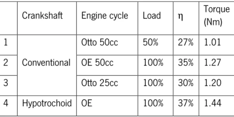
4. Results comparison ... 97
4.1 Hypotrochoid crank over-expanded cycle ... 98
4.2 Conventional crank Otto cycle with 1st and 2nd water injection ... 99
4.3 Unconventional crank Otto cycle ... 101
4.4 Unconventional crank Otto cycle with 1st and 2nd water injection ... 101
4.5 Combined cycle ... 102
5. Conclusions and Future Work ... 105
5.1 Over expansion ... 105
5.2 Combustion efficiency improvement ... 106
5.3 Direct water injection ... 107
viii
List of Figures
Figure 1 - Four different combustion chamber geometry’s. ... 7
Figure 2 - Hemispherical combustion chamber and piston with squish band. ... 7
Figure 3 - Difference between swirl (left) and tumble (right). ... 9
Figure 4 - Direct port (left) and helical port (right). ... 10
Figure 5 - Squish effect. ... 11
Figure 6 - Miller cycle P-V diagram. ... 12
Figure 7 - HEHC P-V diagram comparison with Otto and Diesel cycles and the X Engine [26]. .. 13
Figure 8 - Scuderi split cycle engine [28]. ... 14
Figure 9 - Otto cycle P-V and T-S diagrams. ... 14
Figure 10 - Real Otto cycle P-V diagram. ... 16
Figure 11 - Single cylinder research engine used and the fired cylinder pressure graph with conventional and QCV cycles [31]. ... 17
Figure 12 - Engine intake manifold with fuel (red) and water (blue) injectors with common rail. 20 Figure 13 - EconomicUM (left) and UMotor (right). ... 22
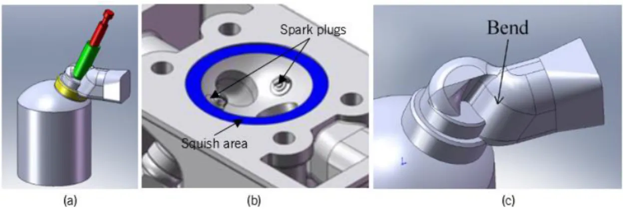
Figure 14 - (a) Intake channel assembly; (b) UMotor combustion chamber showing the squish area and two spark plugs; (c) Working of the helical port. ... 24
Figure 15 - Engine head bottom view (left) and top view (right). ... 25
Figure 16 - Engine head interior assembled components (left) and full assembled engine head (right). ... 26
Figure 17 - Engine cast head. ... 26
Figure 18 - Engine block. ... 27
Figure 19 - 2D piston layout. ... 27
Figure 20 - Connecting rod and piston assembly. ... 28
Figure 21 - Hypotrochoid crank mechanism: (a) Intake (short stroke); (b) Compression (short stroke); (c) Expansion (long stroke); (d) Exhaust (long stroke). ... 29
Figure 22 - Exploded view of the crankshaft. ... 30
Figure 23 - Piston position vs CA. ... 30
Figure 24 - Verticality of connecting rod during power stroke. ... 30
Figure 25 - Hypotrochoid mechanism inside the crankcase ... 31
ix
Figure 27 - Machined crankcase. ... 32
Figure 28 - Section view (left) and rendered view of the full assembled engine (right). ... 32
Figure 29 - Hypotrochoid crank system and connecting rod. ... 32
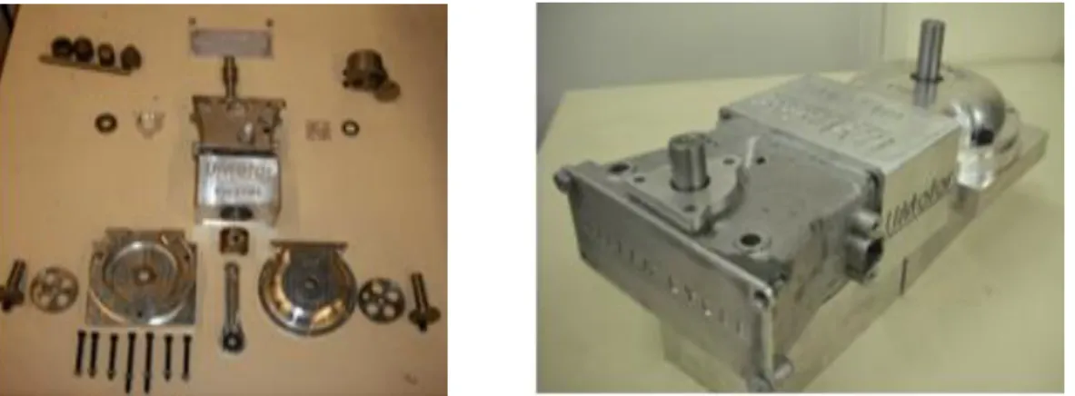
Figure 30 - Exploded view of several parts of the engine and final engine assembly. ... 33
Figure 31 - CONVERGE methodology. ... 36
Figure 32 - Epitrochoid and hypotrochoid crankshaft mechanism. ... 40
Figure 33 - Epitrochoid (left) and hypotrochoid (right) concepts. ... 41
Figure 34 - Epitrochoid (blue) and hypotrochoid (red) centre of the big end bearing of the connecting rod during the 4 strokes. ... 41
Figure 35 - Comparison between hypotrochoid (red line) and epitrochoid (blue line) crankshafts. Both expansions strokes are represented by wide shaded lines. ... 42
Figure 36 - Comparison of minimum connecting rod length for the hypotrochoid (left) and epitrochoid (right) crankshafts. ... 43
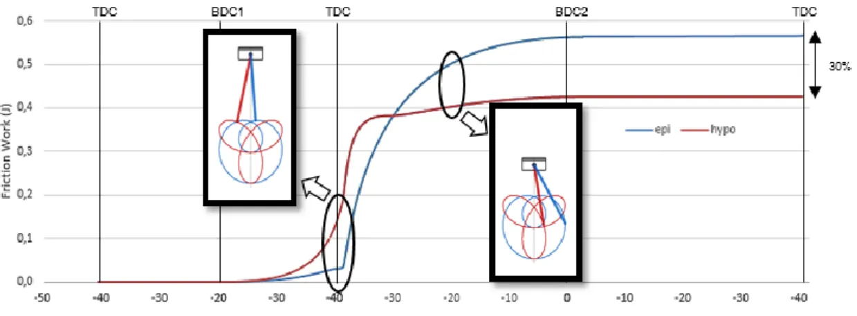
Figure 37 - Friction work comparison between the hypotrochoid and the epitrochoid cranks during the 4 strokes. ... 44
Figure 38 - P-V diagrams for the 4 engine cycles simulated... 45
Figure 39 - Combustion model procedure diagram. ... 49
Figure 40 - Engine combustion chamber and inlet (red) and exhaust (grey) ports. ... 51
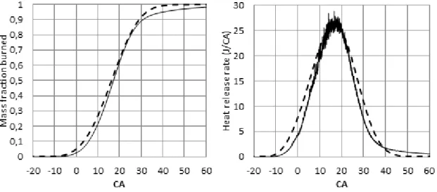
Figure 41 - Mass fraction burned and heat release rate results comparison. 0D engine model (dashed line) and CONVERGE (black line). ... 52
Figure 42 - UMotor surface geometry on CONVERGE Studio. ... 53
Figure 43 - Hypotrochoid crankshaft mechanism piston position vs CA ... 55
Figure 44 - Intake and exhaust valve motions. ... 56
Figure 45 - Swirl ratio (black line) and intake valve lift (black dashed line) vs CA. ... 58
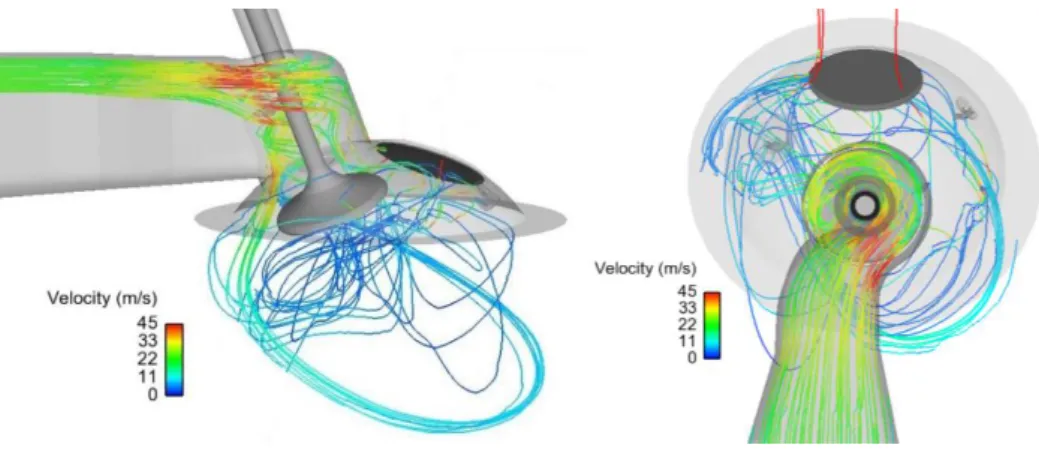
Figure 46 - Two different views of the pathlines of mixture particles swirling through the geometry. ... 59
Figure 47 - Top cross section of the cylinder at different piston positions. The vectors represent the velocity field direction and magnitude (m/s) in the mesh nodes. Bottom view. ... 59
Figure 48 - Top cross section of the cylinder during compression stroke. The vectors represent the velocity field direction and magnitude (m/s) in the mesh nodes. Bottom view. ... 60
x
Figure 49 - Heat release rate and integrated heat release rate results for the three simulations
performed. ... 61
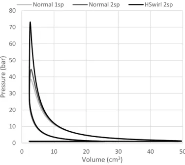
Figure 50 - P-V diagram results from the three simulations performed. ... 62
Figure 51 - Constant temperature isosurface showing the flame front development at different piston position. Top view. ... 63
Figure 52 - Conventional piston motion (dashed black line) and piston motion with TDC dwell (black line) used in the simulation. ... 65
Figure 53 - Mass fraction burned (left) and heat release rate data (right) from the two simulations. Conventional crankshaft (grey line) and unconventional crankshaft (black line). ... 66
Figure 54 - P-V diagram results from the two simulations. Conventional crankshaft (grey line) and unconventional crankshaft (black line). ... 66
Figure 55 - Model combustion chamber wall section. ... 69
Figure 56 - Exhaust valve description. ... 72
Figure 57 - Exhaust valve model boundaries. ... 72
Figure 58 - Measured values [77] (left) and calculated (right) of cylinder head surface temperature. ... 75
Figure 59 - Heat flux histories for five consecutive individual cycles 198-cycle average 1500 rev/min, AFR=18, Load=40%, MBT timing [3] (left) and surface heat flux model results for same conditions (right). ... 75
Figure 60 - Pressure (a) and Temperature (b) of the gases as a function of crank angle for MBT. ... 76
Figure 61 - Envelopes of the temperatures along the wall depth during one cycle for normal engine operation at 1500 rpm (light grey), 3000 rpm (grey), 6000 rpm (black). ... 77
Figure 62 - Wall surface temperature for normal engine operation at 1500 rpm, 3000 rpm, and 6000 rpm. ... 77
Figure 63 - Wall surface temperature above the minimum value for normal engine operation at 1500 rpm, 3000 rpm, and 6000 rpm. ... 78
Figure 64 - Distribution of energy on a typical SI Engine as a function of engine speed [3]. ... 79
Figure 65 - Envelopes of the temperatures along the valve thickness during one cycle for normal engine operation at 1500 rpm (light grey), 3000 rpm (grey), and 6000 rpm (black). ... 80
xi Figure 66 - Exhaust valve face temperature above the minimum value for normal engine operation
at 1500 rpm, 3000 rpm, and 6000 rpm. ... 81
Figure 67 - Model predictions at 5, 10, 30 and 50 atmospheres (in addition to the results achieved by Halvorson [79]) [78]. ... 83
Figure 68 - Investigation of the cooling of hot walls by liquid water sprays [80]. ... 84
Figure 69 - Heat release from the gases to the wall and heat retrieved from the water injection. 85 Figure 70 - Envelopes of the temperatures along the combustion chamber thickness during one cycle with water injection for different CA. ... 86
Figure 71 - Inner wall surface temperature during one engine cycle. ... 87
Figure 72 - Total Heat and mass flux for 𝜀=1 ... 88
Figure 73 - Total heat and mass flux for 𝜀=0.88 ... 89
Figure 74 - Exhaust valve model boundaries with water injection. ... 89
Figure 75 - Envelopes of the temperatures along the valve thickness during one cycle with water injection for different CA. ... 90
Figure 76 - Valve face temperature during one engine cycle. ... 90
Figure 77 - Total Heat and mass flux for 𝜀=1. ... 92
Figure 78 - Total heat and mass flux for 𝜀=0.94. ... 93
Figure 79 - WFR varying engine speed for the exhaust valve (dashed black line) and combustion chamber (black line). ... 94
Figure 80 - Water Injection duration varying engine speed for the exhaust valve (dashed black line) and combustion chamber (black line). ... 94
Figure 81 - Engine cycle P-V diagram. 1 – Otto cycle Eff1=29%; 2 – Over-expanded cycle Eff2=37%; Effi=28%. ... 99
Figure 82 - Engine cycle P-V diagram. 1 – Otto cycle Eff1=29%; 3 – Otto cycle with 1st water injection Eff3=31%; Effi=7%. ... 100
Figure 83 - Engine cycle P-V diagram. 1 – Otto cycle Eff1=29%; 4 – Otto cycle with 2nd water injection Eff4=32%; Effi=10%. ... 100
Figure 84 - Engine cycle P-V diagram. 1 – Otto cycle Eff1=29%; 5 – Otto cycle with CVC Eff5=31%; Effi=6%. ... 101
Figure 85 - Engine cycle P-V diagram. 1 – Otto cycle Eff1=29%; 6 – Otto cycle with CVC and 1st water injection Eff6=33%; Effi=13% ... 102
xii
Figure 86 - Engine cycle P-V diagram. 1 – Otto cycle Eff1=29%; 7 – Otto cycle with CVC and 2nd
water injection Eff7=35%; Effi=20% ... 102
Figure 87 - Engine cycle P-V diagram. 1 – Otto cycle Eff1=29%; 2 – Combined cycle Eff8=50%;
xiii List of tables
Table 1 - Reduction of different losses for improved fuel economy. ... 2
Table 2 - UMotor principal specifications. ... 23
Table 3 - Engine cycles simulated using the Simulink engine model. ... 44
Table 4 - Efficiency and torque results for the 4 different engine concepts. ... 46
Table 5 - Engine specifications. ... 50
Table 6 - Engine conditions. ... 51
Table 7 - Combustion results. ... 51
Table 8 - Boundary conditions and functionality. ... 54
Table 9 - UMotor valves motion specifications. ... 55
Table 10 - Region events. ... 56
Table 11 - Region initialization values. ... 57
Table 12 - Combustion results. ... 60
Table 13 - Boundary conditions and functionality. ... 64
Table 14 - Engine and combustion conditions and results. ... 65
Table 15 - Engine specifications. ... 74
Table 16 - Combustion chamber material and geometric specifications. ... 74
Table 17 - Exhaust valve material and geometric specifications ... 74
Table 18 - Combustion model results for 1500, 3000 and 6000 rpm at WOT and ignition advance for MBT. ... 76
Table 19 - Temperature model conditions. ... 85
Table 20 - Water injection conditions. ... 87
Table 21 - Mass and heat flux required. ... 87
Table 22 - Water injection conditions. ... 91
Table 23 - Mass and heat flux required. ... 91
Table 24 - Features and corresponding technologies. ... 97
Table 25 - Simulations characteristics. ... 98
xiv Symbols
𝑎 - Efficiency factor 𝐴 - Area
𝑐𝑣 - Specific heat at constant volume 𝑐𝑝 - Specific heat at constant pressure 𝑑 - Pipe diameter
𝐷 - Cylinder bore
ℎ - Heat transfer coefficient
ℎ̅ - Medium heat transfer coefficient 𝑘 - Thermal conductivity
𝑙 - Cell width 𝐿 - Pipe length 𝑚 - Mass
𝑚̇ - Mass flow rate 𝑀 - Form factor
𝑀𝐹𝐵 - Mass fraction burned 𝑛 - Polytrophic index 𝑁𝑢 - Nusselt number 𝑄 - Heat transfer 𝑄̇ - Heat flux 𝑅𝑒 - Reynolds number 𝑆 - Swirl number 𝑆𝑝 - Mean piston speed
xv 𝑡 - Time
𝑇 - Temperature 𝛼 - Thermal diffusivity 𝑊 - Work
∆𝑤 - Water injection duration 𝑥 - Dilution mass fraction
𝜀 - Droplet heat transfer effectiveness 𝜇 - Dynamic viscosity
𝜂 - Efficiency 𝜃 - Crank angle 𝜌 - Density Ω - Angular speed
xvi
Subscripts
air – Fresh air/intake mixture comb – Combustion
drop – Droplet f – Final flow – Air flow
gas – Remaining hot gases i – Initial in – Inlet inj – Injected out – Outlet tot – Total vap – Vapour
xvii Abbreviations
AFR – Air fuel ratio
ATDC – After top dead center BDC – Bottom dead center BTDC – Before top dead center CA – Crankshaft angle
CAD – Computer aided design CFD – Computer fluid dynamics CNC – Computer numeric control CR – Compression ratio
CVC – Constant volume combustion DISP – Displacement
EGR – Exhaust gas recirculation HEHC – High efficiency hybrid cycle ICE – Internal combustion engine IVO – Intake valve opening LIVC – Early intake valve closure MBT – Maximum brake torque MFB – Mass fraction burn
NeCCoRC – Nested coaxial counter rotating cam OEE – Over-expanded engine
QCV – Quasi-constant volume STL – STereoLithography
xviii
TDC – Top dead center TTW – Tank-To-Wheel VSE – Variable stroke engine WFR – Water fuel ratio WOT – Wide open throttle WTW – Well-To-Wheel
1
1. Introduction
The society is more and more focused on the quest for efficiency in order to reduce waste in every aspect of life [1]. The same is happening in the automotive industry and particularly concerning internal combustion engines (ICEs), where the wasted energy and pollutant emissions are still quite significant [2]. Nowadays we are witnessing a paradigm shift on the automotive industry towards electric mobility which has a good potential for efficiency improvement. Still, on a life cycle analysis perspective (Well-To-Wheel - WTW) the efficiency and emission record of electric vehicles will depend also on the efficiency and emissions of the electricity production and transport. ICEs might sometimes be less pollutant and aggressive to the environment as long as their efficiency (Tank-To-Wheel - TTW) is high. Indeed, when electricity is produced from thermal power station, the overall WTW efficiency might be lower when compared to efficient vehicles using ICEs.
However ICEs suffers from fairly low efficiency due to theoretical thermodynamic limitations of ideal cycles as well as additional energy losses due to deviations from ideal cycles such as heat transfer from the hot burning gases to the combustion chamber walls, among many others [2]. From the theoretical 62% efficiency of the Otto cycle typically only 30% of the fuel energy is converted into useful work; 35% is lost as heat by the cooling system, and another 35% is lost within the exhaust gases [3]. Therefore there is still a long way to achieve really efficient ICEs.
A lot of effort in engine research and development in recent years has been dedicated to the use of technologies such as Variable Compression Ratio, Variable Valve Timing or Charge Stratification in order to maximize efficiency. This highlights to current general tendency to create and design engines that work under different conditions depending on the demand, with constant improvement of fuel consumption.
The studies performed in this work aim to provide innovative ways of improving ICE efficiency using unconventional technologies and mechanisms, differently than what is being actually developed by the big automotive industries. Nonetheless, the objective is always the decrease of fuel consumption and thus the efficiency enhancement of engines using novel technologies.
Some of the sources of inefficiencies or losses in the spark ignition ICEs are presented in Table 1. The several technical solutions studied in this work aim to minimize those losses. The table also
2
shows some of the ways way that those technologies can improve engine performance by reduction of the referred losses.
Table 1 - Reduction of different losses for improved fuel economy.
The present work presents the potential benefits of unconventional ways to increase engine efficiency, by using two different crankshaft designs, a hypotrochoid crankshaft and a cam crankshaft. Direct water injection, turbulence generation in the intake channel and combustion chamber design. All these features are studied using a base engine called the UMotor.
In the following section (Chapter 2) an analysis will be made to these technologies, focusing on the achievements reached in the past years in terms of engine thermal efficiency and other performance measures. Additionally is presented a detailed description of the UMotor development, an overview of the commercial computer fluid dynamics (CFD) software and a 0D model, created in Matlab Simulink, used to perform the present studies.
Chapter 3 contains the detailed efficiency improvement analysis of all the features proposed. Starting with the over-expansion using the hypotrochoid crankshaft of the UMotor, the piston friction using the unconventional crankshaft is calculated. Then the thermodynamic efficiency of the UMotor is calculated using the 0D engine model. On the combustion efficiency improvement, a CFD simulation using the UMotor combustion chamber is performed to quantify the combustion efficiency improvement using turbulence generation, improved combustion chamber design and two spark plugs. Constant volume combustion, using a cam crankshaft, was also simulated using the CFD software in order to determinate and quantify the combustion and thermodynamic efficiency improvement. A combustion 0D model developed by the author, in order to be
Ove r-expan sion Wa ter inj ectio n Isocho ric
combustion Turbulence Enha
nceme nt Com bustion chamber design Exhaust to ambient x x Combustion duration X x x Heat losses x x
3 implemented on a wall temperature model, is detailed and validated using the CFD software. The chapter is finalized with a wall temperature model description along with the direct water injection feature to cool the combustion chamber and valve walls.
Chapter 4 shows all the features results comparison using the engine cycle Pressure-Volume (P-V) diagram calculated using the 0D engine model in Matlab Simulink.
5
2. State of the art
2.1 Combustion Chamber Design
The combustion chamber shape is extremely important to achieve high combustion efficiency. Therefore a lot of importance has been put on the combustion chamber design over the years of engine research. Initially the cylinder head was little more than a cover for the cylinder where the simplest configuration was the side valve engine with the inlet and exhaust valves together at one side of the cylinder. The most successful combustion chamber for the side valve engine was the Ricardo turbulent head [4]. This design was the result of extensive experimental studies aimed at improving combustion.
Nowadays there are many different combustion chamber shapes. The principal characteristics of the combustion chamber that will change the combustion efficiency of an ICE are:
Compactness;
Spark plug position;
Controlled wall temperature;
Gas exchange area, and valve position;
Turbulence generation intensity;
Intake and exhaust channels position.
The first four characteristics are inherent to the combustion chamber design. The last two are related to the intake and exhaust channels design and the valve system. The objectives of those chamber design characteristics which are related to engine efficiency and emissions are [3]:
Fast combustion process, with low cycle by cycle variability;
Minimum heat loss to the combustion chamber walls;
Low fuel octane index requirement.
To achieve those major design objectives some considerations have to be taken in the design procedure of a combustion chamber [3]:
Minimization of the distance travelled by the flame front; by minimising the distance between the spark plug and the end gas, combustion will be as fast as possible reducing
6
the time available for the chain reactions that lead to knock to occur. This implies that, for geometrically similar engines, those with the smallest diameter cylinders will be able to use the highest compression ratios;
The exhaust valve and spark plug should be close together; the exhaust valve is very hot (possibly incandescent) so it should be positioned as far from the end gas as possible to avoid inducing knock or pre-ignition;
Turbulence generation; there should be sufficient turbulence to promote a rapid combustion. However, too much turbulence will lead to excessive heat transfer to the chamber walls and also very fast combustion is noisy;
The end gas should be in a cool part of the combustion chamber; the small clearance between the cylinder head and the piston in the squish area forms a cool region. Since the inlet valve is cooled during the induction stroke, it too can be positioned at the end gas region.
The advancements achieved in the knowledge of the fundamentals of spark ignition engine combustion, in cylinder gas motion, and heat transfer allow nowadays to perform a rigorous procedure for evaluating these factors and develop an optimized combustion chamber. This procedure leads to an optimum combustion chamber design with the following features:
Compact (low surface/volume ratio) using under-square engines (stroke larger than the bore) as these have combustion chambers with a better surface to volume ratio;
Central spark plug, or two spark plugs per cylinder;
Flame front area increasing with its progression (hemispherical combustion chamber);
Valves position so as to increase the gas exchange area, and exhaust valves not excessively big in order to increase the cooling efficiency;
High turbulence generation without penalizing volumetric efficiency.
Very often the production and economic considerations rather than the thermodynamic considerations will determine the type of combustion chamber used. In the case of low production volume, custom-built engines used in high level motorsport competitions, this factor is normally not that relevant.
7 A study done by S. G. Poulos [5] shows the effect of four different chamber geometries on flame front area, and thus on combustion efficiency (Figure 1).
The bowl-in-piston chamber gives flame surface areas which are 30 to 45 percent larger than those obtained with the disc chamber under equivalent conditions around top dead centre (TDC). The hemispherical and open chamber showed gains of about 30 percent relatively to the equivalent disc configuration. For a given chamber shape, the flame area depends even more significantly on plug location. Shifting the plug from a side to a central location may increase the peak flame area by 150 percent [5]. When it is not possible to locate the plug centrally, 2 plugs should be placed at the sides.
The hemispherical chamber with a centre location plug has the fastest combustion process, relatively to burn rate results for different chamber geometries. This type of combustion chamber shows good compactness which, coupled with large valve diameters, allows a good compromise between power and combustion stability at low speeds. There is normally a small amount of squish provided at either side of the valve ports. Nevertheless, more squish can be created, if necessary, by using a raised or domed piston-crown (Figure 2).
Figure 2 - Hemispherical combustion chamber and piston with squish band.
Brunt [6] in his doctoral thesis on combustion chamber design showed that:
The cylinder pressure and mass burn (combustion) rate can be significantly altered by changing the chamber design. The design parameters having the greatest effect are the
Disc
Open Hemi Bowl-in-piston
8
number of spark plugs, spark plug location, and compression ratio and chamber shape. Chambers producing high combustion rates were found to have reduced cyclic dispersion;
For lean burn engines, dual spark plugs designs were shown to provide improved performance over single spark plug designs. With single ignition, a bowl in piston arranged such that it provides about 60% of squish area associated with a centrally located spark plug should provide reasonable lean mixture performance.
Several papers have been published showing the effects of using dual spark plugs. Caris et al [7] has presented results showing that dual spark plugs can provide a considerable reduction in burn time, whilst Quader [8] has confirmed that both spark plug location and the existence of an extra spark plug have a large effect on combustion duration and on the lean limit. Oblander et al [9] shown that a reduction in combustion duration and cyclic dispersion could be obtained with two spark plugs.
Nakajima et al [10] compared the results from a compact wedge chamber with a "fast burn" engine of a zero squish, hemispherical head, and dual ignition design. The results show that the dual ignition design is superior to the squish design concerning combustion rate, cyclic dispersion and exhaust gas recirculation (EGR) tolerance.
2.2 Turbulence Generation
There are several important parameters to allow the development of an efficient, fast and complete combustion in ICEs. These parameters can be related to the engine design or engine command, combustion chamber design, compression ratio, turbulence or ignition advance, air fuel ratio (AFR), mixture preparation level, load and engine speed.
It’s important to have a fast start of combustion, and a fast burn rate. If the combustion duration is instantaneous, it falls within the constant volume combustion theoretical cycle which has high thermal efficiency.
If combustion happens within a stationary mixture (no fluid movement and turbulence), an extremely slow burn will take place. That couldn’t occur at medium to high engine speeds. On practice, because of the fact that the mixture has to travel through channels and valves, and it is compressed on the cylinder, high turbulence is expected just before combustion occurs. In this case combustion can be 10 times faster than one occurring within a stationary mixture [2].
9 To enhance the efficiency of an ICE it is important to optimize its thermal efficiency, which is obtained at the highest possible compression ratio. But if the compression ratio is too high there is a chance that knock will occur, which should be avoided. A solution for this problem is to promote a very fast combustion, to reduce the time available for that phenomenon to occur.
Sufficient large-scale turbulence (kinetic energy) is needed at the end of the compression stroke to promote a rapid combustion. This turbulence will result in a better mixing process of air and fuel and it will also enhance the flame development. However, too much turbulence leads to excessive heat transfer from the gases to the cylinder walls and may create problems of flame propagation [11-13]. The key to efficient combustion is to have enough turbulence in the combustion chamber prior to ignition. This turbulence can be created by the design of the intake port [11].
There are two types of structural (large scale) turbulence that are recognizable in an engine; swirl and tumble (Figure 3). Both are created during the intake stroke. Swirl is defined as the charge that rotates concentrically around the axis of the cylinder. Tumble is defined as the in-cylinder flow that is rotating around an axis perpendicular to the cylinder axis.
Figure 3 - Difference between swirl (left) and tumble (right).
While tumble is generally existent in 4-valve pent roof combustion chambers, swirl is more common in 2-valve heads [12]. If the inlet flow is brought into the cylinder with an initial angular momentum, it will create swirl [11] [12].
As mentioned above, turbulence should not be too high or it could lead to excessive heat transfer from the mixture to the cylinder walls and even flame propagation problems [14]. Furthermore, a very high swirl is not desirable as the kinetic energy for the flow is obtained at the expense of a reduced volumetric efficiency. Finally, it may be said that an optimal swirl ratio is not only good for optimum combustion but also for an optimal emission reduction [12].
10
There are two ways of creating swirl, by valve design and by intake design [3]. The design needs a shape that creates turbulence during the intake stroke that still lasts during the compression stroke. Commonly two designs can be used to create swirl: the direct port and the helical port [3] (Figure 4). These ports basically differ in their shape around the valve stem. The helical port concept relies on the assumption that the flow upstream of the valve curtain is induced into rotation and therefore enters the combustion chamber with an angular momentum along the valve stem axis. This in turn should result in a higher fluid rotation within the cylinder. The idea of a helical port is that the air is already rotating prior to entering the cylinder, because of the inlet port design. The rotation is achieved by forcing the air around the valve stem, so that an angular momentum along the cylinder axis is created as the charge enters the cylinder. The swirl of a direct port relies solely on the interaction of flow and cylinder walls.
Figure 4 - Direct port (left) and helical port (right).
Helical ports normally have a higher discharge coefficient than direct ports for equivalent swirl levels [3]. Another advantage of helical ports is that they are not that sensitive to shape defects that may occur due to the casting process. Also, a helical port produces more swirl than a direct port. There is a further constrain for the intake port design which is the manufacturing (casting) requirements.
Experimental studies [15] [16] show that swirl has large-scale effects on flow fields, flame size, shape, stability, and combustion intensity, which are affected by the degree of swirl. This degree of swirl usually is characterized by the swirl number, S, which is a non-dimensional number representing the ratio of the axial flux of angular momentum to the axial flux of axial momentum. The swirl number aims to provide a relative measure of the strength of circulating flow inside the cylinder following the air intake. S ranges below or above 0.5 are considered to be low and high swirl levels, respectively [3].
11 During induction, the generated turbulence may be swirl or tumble, depending on the flow pattern, while during the end of compression there is a different kind of turbulence that may be induced, called squish. The squish effect happens at TDC when the piston crown comes very close to the cylinder head (Figure 5). The mixture is suddenly "squished" out within the combustion chamber, creating turbulence.
Figure 5 - Squish effect.
Swirl may also be generated in twin inlet valve engines, by deactivating one of the intake valves or intake passages during induction (using port de-activation throttles [15]). The use of high swirl ratios increases the heat release rate during combustion, reducing the combustion duration. At the same time, the heat transfer ratio increases with a reduction in the thermal efficiency of the engine. However there are benefits in the reduction of HC emissions, due to a more complete combustion. Nagayama et al [16] measured flame speeds using two ionisation probes and compared four combustion chambers combining both squish area and swirl. They found that both squish and swirl increased the flame speed and that maximum speeds were achieved when the squish and swirl were combined. It is interesting to note that squish was effective in increasing the flame speed during both the initial and the main combustion phases.
2.3 Over-expansion
The majority of the engines used in the automobile industry around the world are based on the Otto cycle. When the exhaust valve of this kind of engines opens, there is still a fair amount of energy in the cylinder, in the form of pressure and temperature (enthalpy) of the exhaust gases that is lost through the exhaust blow-out [2] [3] [17].
With an over-expanded cycle engine, in which the expansion stroke is longer than the intake stroke, it is possible to significantly reduce this wasted energy, enhancing the efficiency of the engine [2].
12
A type of over-expansion concept using charge intake to increase the lower torque resulted by the over-expansion was patented by Ralph Miller, an American engineer, in the 1940s, but the concept was proposed earlier by Atkinson.
The Atkinson cycle takes all the exhaust gas enthalpy by performing expansion to atmospheric pressure. The Miller cycle only takes part of that enthalpy being also super-charged. The over-expanded engines are called Atkinson or Miller even if none of this denominations are completely true. On this work only the over-expanded denomination will be used.
Previous work by the laboratory of thermal engines of the University of Minho has shown the potential for over-expansion, especially when combined with optimized compression ratios [18] [14] [19] [20] [21], with a Patent having been issued [22]. The over-expansion was achieved with a Late Intake Valve Closure (LIVC) strategy, in which the effective intake and compression strokes are reduced while keeping unaltered the expansion (and exhaust) stroke. This strategy is highly attractive in terms of simplicity. Its main disadvantage is that this reduction of the intake stroke induces a proportional reduction in engine power. An alternative would be to increase the expansion stroke instead of decreasing the compression stroke. This is only possible by having physically different compression and expansion strokes using a non-conventional crank mechanism [23]. This is the approach chosen for the present work.
The P-V diagram presented on Figure 6 shows the efficiency gain of the theoretical over-expanded cycle in relation to the more usual Otto cycle [14]. This gain is presented by the grey area limited by the points 4,5,6,1. In fact, these P-V diagram areas actually represent work (∫P∙dV).
Figure 6 - Miller cycle P-V diagram.
Real Miller cycle engines (with supercharging) were produced by Mazda in the 1980s. They had a fixed LIVC and were supercharged. In 1993, Mazda introduced in the market a supercharged Miller cycle gasoline engine as an answer to the requirement of CO2 emissions reduction [24].
13 An ICE linked to an electric motor by a planetary gear system (Toyota Hybrid System) was fitted by Toyota on its car model Prius [25]. The ICE had a displacement of 1497cc, with a geometric compression ratio of 13.5:1, but the effective compression ratio was limited to the range of 4.8:1 to 9.3:1 by using variable valve timing to time the intake valve closing between 80º and 120º after bottom dead centre (ATDC). In order to minimize friction losses the engine speed was lowered. The specific fuel consumption was reduced to a level of 230 g/kWh.
Another method for realizing over-expansion is by crankshaft offset. This consists on deviating the axis of the crankshaft relatively to the axis of the cylinder. By doing this, the piston motion is modified and the cycle strokes duration is changed, depending on the side to which the crankshaft is offset.
The “High Efficiency Hybrid Cycle” (HEHC) used on the X Engine [26], borrows elements from Otto, Diesel, Atkinson and Rankine cycles (Figure 7). It is a rotary engine with some particular features. Air is compressed and introduced in a separate combustion chamber where fuel is injected and combustion occurs under truly isochoric conditions. After the combustion is complete, the burned gases are expanded in a separate expansion chamber, which has an expansion ratio higher than the compression ratio of the compression chamber. The HEHC engine is reported to be two to three times more fuel efficient than today’s engines over an automotive drive cycle (from 17-25% to over 50% efficiency) [27].
Figure 7 - HEHC P-V diagram comparison with Otto and Diesel cycles and the X Engine [26].
Finally, the split cycle engines are the ones which separate the 4 strokes (intake, compression, power and exhaust) of conventional engines in to two separate paired strokes to occur in two separate cylinders, namely compression and power cylinders. Scuderi split cycle engine (Figure 8) was named after the concept proposed by Carmelo Scuderi [28]. The engine works the same way
14
as split cycle engines with slight modifications in order to overcome the drawbacks of the ordinary split cycle engines. The over-expanded cycle on this engine is a function of its architecture where the compression stroke volume is smaller than the power stroke volume.
Figure 8 - Scuderi split cycle engine [28].
2.4 Constant Volume Combustion
The theoretic Otto cycle includes processes of isentropic compression and expansion and isochoric (constant volume) supply and loss of heat. The graphical presentation of the ideal Otto cycle is illustrated on Figure 9 with the P-V and T-S diagrams.
Figure 9 - Otto cycle P-V and T-S diagrams.
1 – 2 Isentropic process. The gas is compressed by the work done. The compression stroke begins at bottom dead centre (BDC) and is an isentropic, i.e., adiabatic, process.
2 – 3 Isochoric process. The air fuel mixture burns instantaneously at TDC. All heat release (combustion) takes place at constant volume at TDC.
15 3 – 4 Isentropic process. The gas is expanded, producing work. The expansion stroke begins at TDC and is an isentropic and adiabatic, process.
4 – 1 Isochoric process. The loss of heat shown in the T-S diagram crossing the 4-1 line. A heat rejection process (exhaust) occurs at constant volume at BDC. The constant volume process is thermodynamically efficient. It is called a constant volume process because the heat supply (representing the real combustion phenomenon) occurs at a constant volume. The thermal efficiency of this process follows:
𝜂 = 𝑊 𝑄0 = 1 − |𝑄1−4| 𝑄2−3 = 1 − 𝑇4− 𝑇1 𝑇3− 𝑇2 = 1 − 𝑇1 𝑇2 𝑇4 𝑇1− 1 𝑇3 𝑇2− 1 ( 1 )
In conventional engines, because of the piston movement created by the crankshaft, the heat supply would have to occur infinitely fast, i.e. abruptly. However, that is not realistically feasible unless an unconventional crank mechanism is used.
In fact, real cycles applied in ICE cannot achieve the levels of performance suggested by ideal thermodynamic cycles. One of the main differences has to do with heat release (combustion) timing, which does not occur isochorically. In fact, the combustion starts way before the piston reaches the TDC and takes place during a significant part of the downward stroke of the piston. The traditional design of ICEs using a crank connecting rod system simply does not allow the constant volume combustion to take place, significantly reducing the efficiency of the cycle. Comparing with the theoretical Otto cycle (Figure 9) with the real Otto cycle (Figure 10) there are some differences that can be described and understood on the following label of Figure 10.
16
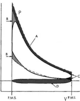
Figure 10 - Real Otto cycle P-V diagram.
A – Heat transfer during combustion and power stroke. B – Non instantaneous combustion (non isochoric). C – Exhaust valve opening.
D – Pressure drop between intake and exhaust strokes.
The use of a conventional crankshaft limits the type of movement that aims to give the piston, being necessary to create different mechanisms to fulfil this function. The possibility of effectively stopping the piston at TDC for some time while the crankshaft continues its rotation allows for constant volume combustion.
The main advantages of producing a near constant volume combustion relate to increasing maximum pressure near TDC even using a smaller spark advance value, which leads to higher efficiency and higher work produced. The disadvantages lies in the need to use unconventional systems in spite of the crankshaft which in turn are quite complex.
Multiple link mechanisms [29] and crankless cam-driven engines can be used to significantly modify the conventional piston motion, either by slowing the piston speed near TDC or by effectively stopping the piston motion at TDC during some crankshaft angle (CA) degrees (DWELL). The characteristics of crankless cam-driven engines allow the replacement of the conventional crankshaft, being possible to induce whatever a piston movement is desired. This allows to focus
P
17 on the study of different movements of the piston during combustion, using various DWELL amplitudes at TDC to effectively implement a constant volume combustion strategy.
One of the works proposed in this field [30] implemented the constant volume combustion by stopping the piston at TDC during 20 CA degrees. The crankshaft design was not presented by the author. The engine efficiency improvement relatively to a conventional crankshaft was reported to be 11% at full throttle.
Another author [31] performed quasi constant volume (QCV) combustion by using a high torque, high bandwidth, permanent magnet electric drive system attached to the crankshaft. The system enabled strong reductions in piston velocity around TDC (Figure 11). A quasi constant volume combustion was thus been successfully achieved, leading to an improvement in the pressure integral of the cycle of 11% relatively to the conventional cycle.
Figure 11 - Single cylinder research engine used and the fired cylinder pressure graph with conventional and QCV cycles [31].
A zero dimensional model was used by Doric [32] to investigate the combustion performance of a four cylinder petrol engine with unconventional piston motion. The kinematic scheme of the crankshaft used is very similar to a conventional crankshaft mechanism. Different piston motions near TDC were performed and overall, the obtained pressure integral of the combustion cycle was about 4% higher than that of the conventional cycle.
ICVC and APC engines [29] used complex linkage mechanisms to allow the piston displacement to change moderately around TDC and increase the degree of constant volume in order to improve the thermal efficiency. The results showed that the heat loss increased and the thermal efficiency did not improve. The author stated that the higher heat loss came from the fact that high pressure and temperature around TDC were maintained for a longer period of time. Nevertheless, in order
18
to reduce heat loss a direct injection engine was operated as stratified charge combustion and a degree of constant volume increased, leading to an increase of thermal efficiency of 1.1 points topping at 42.7%.
In conclusion, the following statement by Blair [11] is presented, as it illustrates well why this feature should be extensively studied:
“It’s clear that the ideal Otto cycle is ineffective in simulating combustion in a spark-ignition engine, compared to data measured in a real engine. The problem is simply that an engine cannot conduct combustion at constant volume, i. e., instantaneously at TDC, because a real burning process takes time, the piston keeps moving, and the cylinder volume changes. If this latter problem could be remedied by keeping the piston stationary at TDC while combustion took place and then moving it down on the power stroke when all is burned, the imep and power would increase by some 50%. So also would the thermal efficiency improve as it would require no more fuel per cycle. Needless to add, many have tried to induce stop-go piston motion characteristics into both 2 stroke and 4 stroke ICEs. So far none has succeeded, using a plethora of mechanical contraptions on linkages, or at least none are known to be in mass production. The tone of this comment may imply that I think that they never will succeed, not so as I have accepted long ago that there is no limit to human inventiveness. To the contrary, I would actually encourage the world’s inventors to keep on trying to accomplish this ICE equivalent of the search for the Holy Grail.” Gordon P. Blair.
2.5 Direct Water Injection
The ideal Otto cycle consist of isentropic compression, combustion, isentropic expansion and gas exchange and does not include any form of heat transfer. In contrast to the case with other types of heat engine, heat transfer in the ICE is totally undesirable.
Heat transfer plays an important role in the conceptual and detail design of the engine. The strong heat release within the engine would lead to excessive thermal loading of some engine components, if some sort of cooling would not be employed. But conventional engine cooling normally affects thermal efficiency, because the thermal load retrieved from the engine for this purpose will not be used to produce mechanical work.
The development of new ceramic materials [33] able to withstand high temperatures has raised the question of whether it could one day be possible to discard engine cooling altogether and build
19 an adiabatic engine with zero heat loss. The cyclic nature of the ICE process hinders efforts in this direction considerably, so that the ideal situation of an adiabatic engine is virtually unachievable. At best, a thermally insulated engine would result, where indeed no net heat would be lost through the walls, but would be stored within the insulating material during the combustion process only to be transfer back to the gas during the gas exchange phase.
A few years ago some so-called adiabatic engines were developed [2]. They were not truly adiabatic (they had minor heat losses) but did have greatly reduced heat loss at the combustion chamber. They usually had no coolant jacket or finned surfaces, and the only heat losses were those related with convection at the external surface of the engine. This resulted in much hotter internal engine components and losses in brake power output, as the intake air was immensely heated by the hot walls and its density was therefore significantly reduced, affecting volumetric efficiency.
Because they had no cooling system (water pump, water jacket, finned surfaces, etc.) adiabatic engines could be made smaller and lighter than conventional engines. Vehicles could be made more aerodynamic with a lower drag coefficient because there would be no need for a radiator. This also gives greater flexibility for engine location and positioning.
The adiabatic engines proposed in those times were all compression ignition engines. The concept cannot be used in spark ignition engines because the hot cylinder walls would heat the air-fuel mixture too quickly and knock would be a prevailing problem.
Nevertheless, the concept of an adiabatic engine in the sense of an engine that does not have significant thermal losses to the outside (except through the exhaust gases) could still be achieved by internally cooling the engine walls. This could be done by using direct water injection, and it would allow spark ignition engines to virtually operate as adiabatic engines. This strategy makes a lot of sense on an energy efficient point of view, since the energy retrieved from the walls with this method may be converted into useful work through phase change and expansion. This internal heat recovery concept is known as internal regeneration.
The injection of water into a combustion engine is not a new concept. During World War II, water injection was extensively used in both Allied and Axis aircraft. These aircrafts were all powered by piston engines, and most were supercharged. In the 1940s NACA (the predecessor to NASA) reported extensively on ICE water injection experiments [34-37].
20
In 1983, Renault started using water injection at the intake system of their turbocharged 1.5 litre Formula 1 engine, after the inter-cooler. The system used a 12 litre tank and a dedicated control unit. An electric pump, pressure regulator and pressure sensor were used. It was reported that the inlet air temperature reduction achieved with this strategy was 10 to 12 ℃, dropping the intake air temp from around 60 to 50 ℃ [38].
The injection of water in the intake manifold is sometimes used, in turbocharged engines, to increase power output avoiding engine overheating and knock. Water or a mixture of water and methanol is injected into the intake manifold (Figure 12) lowering the temperature of the mixture. This allows the increase of boost pressure, compression ratio and ignition advance, all leading to the improvement of torque, power and even efficiency. Water injection can also be used in normally aspirated engines to increase charge density and the ability to use higher ignition advance values without the onset of knock.
Figure 12 - Engine intake manifold with fuel (red) and water (blue) injectors with common rail.
Water injection is still currently object of study, namely in diesel engines in order to reduce the production of NOx and even a slight increase in power due to the expansion of the water vapour [39].
The production of mechanical work obtained from separate the expansion of water injected directly into the cylinder has been examined in several works [40-42]. These engines are called 6 stroke engines, and are based on a 4 stroke engine with 2 additional strokes. After the normal expansion of a 4 stroke engine, part of the burned gases are exhausted, while the other part is compressed again. The fifth stroke occurs with the injection of water directly into the remaining exhaust gases at high temperature. Water vaporizes producing another power stroke due to its increase in
21 pressure. The sixth and last stroke is the exhaust of water vapour and remaining exhaust gases to the atmosphere.
Those authors only studied the interaction of water and the hot gases but did not examine the interaction of water particles with the walls of the combustion chamber and cylinder, as they used a "conventional" externally water cooled engine.
There are several patents related to water injection in ICEs [43-64]. Some of these patents are related to rather particular or unconventional engines like the split cycle [43], where water injection may be added more easily. Others are related to water injection systems to be implemented in conventional ICEs.
Recently, a numerical and experimental work acceded direct water injection during the compression stroke [65]. Water spray characterization of a multi-hole injector under pressures and temperatures which are representative of engine relevant conditions was investigated for naturally aspirated and boosted engine conditions. The experimental conditions included a range of injection pressures of 34, 68, and 102 bar and ambient temperatures ranging from 30 to 200°C, which includes flash-boiling and non flash-boiling conditions. The engine CFD results highlighted that water injection at 90 degrees before top dead centre (BTDC) showed better vaporization and decreased the formation of liquid wall film on piston surface, cylinder head, and cylinder wall when compared with those for 60 degrees BTDC water injection.
2.6 UMotor Development
2.6.1 Introduction
Nowadays the concerns with environmental problems and the low reserves of petroleum are leading the manufacturers to build less polluting and less consuming engines. The stringent goals for emission reductions and energy efficiency increase proposed by global policies, namely in Europe [66], are pushing the automotive industry towards intense research and development in these fields as never seen before in the automotive history [67]. In this framework, the Academia’s ICE research and training has naturally gained a strong focus on these subjects. The formation of college teams participating in vehicle efficiency related contests such as the Shell Eco-Marathon
22
super-mileage contest has shown to be a good opportunity to promote applied research in this field with highly motivated students and researchers.
Shell organises, on a yearly basis, an event called Shell Eco-marathon. The purpose of this marathon is to race a vehicle on a particular track, at an average speed above 30 km/h with minimum fuel consumption. These vehicles are built by teams of students from different countries and universities. The University of Minho participates in this contest with its car, EconomicUM (Figure 13). A new engine is being developed for this car, called the UMotor (Figure 13).
Figure 13 - EconomicUM (left) and UMotor (right).
The UMotor engine is being developed in order to substitute the old engine with the intention of achieving better consumption results. The author has been involved in the development of this engine, with most of the latest engine developments having been made by him. Some unconventional and interesting features were included to the UMotor specifications with the aim of increasing thermal efficiency. The present work has used this engine as basis for the evaluation of several strategies for efficiency improvement. Therefore, the existing engine features and the developments achieved until now will be described in this section.
2.6.2 Engine specifications
The ICE, currently under development, is a spark ignition engine to be running on gasoline. The main principal difference between the UMotor and a conventional ICE is the engine cycle operation and some unusual mechanical specifications. Thus, the UMotor operates under the over-expanded cycle contrary to the Otto cycle present in the conventional spark ignition engines.
Mechanically the over-expanded cycle is accomplished in this engine using a special unconventional hypotrochoid crankshaft that allows different volume variations, where the intake
23 and compressions are the shorter strokes, and the expansion and exhaust the longer strokes. Further, a high swirl generation intake channel and a hemispherical combustion chamber using two spark plugs was developed to enhance combustion efficiency. The engine specifications are listed on Table 2.
Table 2 - UMotor principal specifications.
Engine type Over-expanded 4 stroke with hypotrochoid crank
Number of cylinders 1
Number of valves 1 intake/ 1 exhaust
Number of spark plugs 2
Bore 39.0 mm
Intake and Compression
stroke 19.5 mm
Power and Exhaust stroke 39.5 mm
Connecting rod length 100.0 mm
Intake displacement 23.2 cc
Expansion Displacement 47.2 cc
Expansion ratio 2.0
Compression ratio 11.0:1
Intake valve diameter 14.0 mm
Exhaust valve diameter 14.0 mm
2.6.3 Engine components and relevant features 2.6.3.1 Head design
Small engines have a very unfavourable surface/volume ratio. In order to minimize this a hemispherical chamber was chosen. The combustion chamber was designed to achieve high combustion efficiency, turbulence generation and use two spark plugs (Figure 14). The piston bore is larger than the hemispherical chamber leaving around the combustion chamber a circular ring, which produces high squish turbulence at TDC.
24
Figure 14 - (a) Intake channel assembly; (b) UMotor combustion chamber showing the squish area and two spark plugs; (c) Working of the helical port.
Intake and exhaust ports are placed on the central axis and valves inclined 50 degrees between them. The intake port is helical for generating a high swirl rate. Swirl turbulence is generated within the intake manifold, around the valve axis. Thus the swirl turbulence is less sensitive to the position of the intake port and it is more intensive.
Two small diameter spark plugs will ignite the mixture. One of the spark plugs is placed near the exhaust port and deflected from the central axis of the combustion chamber.
Sand casting was used to produce the parts to make the head [68]. The cores and moulds were produced by rapid prototyping or by using a core box, which is made of aluminium or wood and created on a 4-axis computer numeric control (CNC) milling machine. But there were some restrictions to the manufacturing process:
The design cannot have sharp angles on the milled core box because the milling cutter cannot produce sharp angles;
The design has to be done without undercuts, otherwise the moulds can’t be opened;
Walls that are too thin to be cast should be avoided. There are also some restrictions on the design of the inlet track:
Casting restrictions apply;
The fuel should be injected towards the inlet valve, impinging over its back. As the inlet is curved to create swirl, care was taken to allow a straight path from the injector to the valve;
25 The optimization of the design was continuously improved using CFD studies in a sequence of several enhanced geometries, leading to an optimal final design [68].
After the design was completed it was possible to make the final assembly which consists of Figure 14 (a)): the intake design with cylinder (grey); valve seat (yellow); valve (red) and valve guide (green).
The principle of this geometry is that the air flow is first deflected to the right when it passes the bend (Figure 14 (c)). Then, the air flows around the valve to the left, creating an angular momentum for the intake flow.
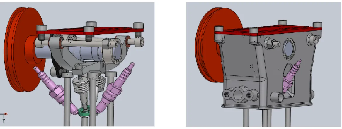
The whole engine was designed with a 3D computer aided design (CAD) software. It was designed by parts, and then assembled. Geometric constraints between the components were set in order to simulate the dynamic behaviour of the system. Figure 15 shows the engine head.
Figure 15 - Engine head bottom view (left) and top view (right).
Subsequently, all the remaining parts of the head engine were designed, including the camshaft, rocker arms, valves, sparkplugs and some other small pieces. The various parts were all assembled, resulting in the final design of the engine head, (Figure 16).
26
Figure 16 - Engine head interior assembled components (left) and full assembled engine head (right).
To obtain good scavenging control and reduce valve mass single inlet and exhaust valves were elected. A single camshaft with roller bearings is located on the cylinder head, in the same vertical plane as the crankshaft and is driven one end via a timing belt. The rocker arm’s contact with the camshaft, valve stem and pivot is made with ball bearings. Both valves have the same dimensions (Ø 12.5 mm) and length (43.5 mm), they are made of stainless steel and are closed by conventional helical springs. Valves are made by Honda [70].
The chosen maximum valve lift was 4 mm to avoid steep cam contours. Valve guides and seats are made of bronze and stainless steel, respectively. Oil splashing lubricates the valve gear train. Figure 17 shows the engine cast head.
Figure 17 - Engine cast head.
2.6.3.2 Cylinder design
The cylinder block (Figure 18) was designed taking into account the existing engine head. The dimensions of the cylinder and the sleeve were defined taking into account the required cylinder capacity and the chosen piston bore (from a Honda GX35 [70]). The volume for the cooling fluid
27 (water) chamber was calculated in order to enable the cooling of the engine during testing, but also to provide a high thermal inertia to the engine during the race. The Eco Marathon is a consumption race where the engine accelerates the vehicle during a short period (≈5s) and then the car coasts for about 5 min before the engine is fired again. The engine is set to work at a specified temperature (95ºC).Therefore, the higher the thermal inertia of the engine, the more stable its temperature will be during the one hour race. Also, the exterior of the engine is to be extensively insulated, as was the case with the current car engine.
The cylinder was machined from a solid aluminium alloy block using a CNC milling machine (Figure 18). The “VSE/OEE” engravement means “Variable Stroke Engine / Over Expanded Engine”.
Figure 18 - Engine block.
2.6.3.3 Piston
The design proposed for the piston enables it to be extremely light and to display a reduced liner contact area (Figure 19).
Figure 19 - 2D piston layout.
28
Figure 20 - Connecting rod and piston assembly.
2.6.3.4 Crankshaft design
The engine was required to be very efficient with a power of nearly 1.5 kW. For the required power a cylinder capacity of 23 cm3 was chosen running at 6000rpm. The over-expanded concept was
used to enhance efficiency, and as the engine should always work at wide open throttle (WOT) an expansion/compression ratio of 2 was chosen and therefore the total cylinder capacity was 47 cm3. The compression ratio was set at 11:1 (geometric).
This system consists of an internal/hypotrochoid gear set in which two cranks have been included. The main crank is responsible for the main alternative movement of the piston (the base stroke), while the additional one is responsible for the variation of the base stroke between intake and expansion. A fixed annular gear with internal teeth and a smaller interior spur gear operating within the latter were used for the hypotrochoid crank mechanism. To obtain our aim for an expansion/compression ratio of 2:1 the required gear ratio is 2:3. This is necessary so that the small crank completes a quarter of a revolution for each stroke, with each stroke corresponding to half of a revolution of the main crank, as depicted in Figure 21. An unitary module was defined for the internal gear set, enabling a good compromise between gear precision, sliding friction and resistance for the desired application. After studying the dimensions and the desired piston stroke, a large annular gear with 90 inner teeth, and an inner spur gear with 60 teeth were chosen. As the module is one, their pitch diameters, in millimetres, corresponds to their number of teeth.
![Figure 11 - Single cylinder research engine used and the fired cylinder pressure graph with conventional and QCV cycles [31]](https://thumb-eu.123doks.com/thumbv2/123dok_br/17704851.828654/39.892.154.737.520.755/figure-single-cylinder-research-engine-cylinder-pressure-conventional.webp)