xx/xx
J. Aerosp. Technol. Manag., São José dos Campos, v10, e4618, 2018
doi: 10.5028/jatm.v10.950 ORIGINAL PAPER
1.Malek Ashtar University of Technology – Faculty of Aerospace – Department of Aerospace – Tehran/Tehran – Iran.
Correspondence author: Saleh Akbaritabar | Malek Ashtar University of Technology – Faculty of Aerospace – Department of Aerospace | Babaii Highway | 15.875-1774 – Tehran/Tehran – Iran | E-mail: [email protected]
Received: Feb. 19, 2017 | Accepted: Nov. 6, 2017
Section Editor: Luiz Martins-Filho
ABSTRACT: Satellites cover a wide range of space missions as remote sensing. Accomplishment of the mission depends on satellite’s stability maintenance and direction. The main task of the attitude control system is to provide stability to the satellite against external disturbances. Such perturbations are caused due to aerodynamic drag, solar radiation and magnetic field. The attitude dynamics model and the development of a controller to stabilize the three degrees of freedom rotational angles are quite important steps in the design of satellites. Although there are several actuators to provide attitude determination and control, a novel type is considered in this paper. This new actuator is the fluid contained inside one or more rings and fluid flow supplied by pump. The required torque control made by change of angular velocity of fluid. In this paper, the satellite is considered rigid and nonlinear dynamics equations were written. Because of the importance of satellite mission, the failure of the pyramid-shaped satellite with an additional ring fluid will be discussed. Satellite attitude control is carried out with an Euler angle errors control law. The performance of this actuator is compared with moment control gyro and their advantages on to each other have been described.
KEYWORDS: Comparing satellite actuators, Fluid rings, Active attitude control.
INTRODUCTION
The attitude control problem has extensive significance for successful completion of any space mission. Unfortunately, satellite attitude may be disturbed by different natural sources such as the Earth’s gravity gradient, Earth’s magnetic field, and solar radiation. Due to importance of stabilization and control in a satellite, several methods have been developed over the decades, which can be divided into passive and active control systems. Pumps are applied in the ACS to change the angular velocity of the fluid inside the rings.
Using a passive method, the system control does not need satellite servomechanisms of attitude control. However, the passive method has lower accuracy and stability than active method. Some active control methods such as micro-thrusters (Patel 2017), reaction wheels (Ismail et al. 2015) and momentum wheels (Jayaram 2009), and control moment gyros (CMGs) (Kawak 2017), are studied in other surveys as well. In the present paper, Attitude Control System (ACS) utilizing fluid rings
Design of Attitude Control
Servomechanisms with Fluid Ring and
CMG for Rigid Satellite
Saleh Akbaritabar1, Reza Esmaelzadeh1, Reza Zardashti1
Akbaritabar S; Esmaelzadeh R; Zardashti R (2018) Design of Attitude Control Servomechanisms with Fluid Ring and CMG for Rigid Satellite. J Aerosp Technol Manag, 10:e4618. doi: 10.5028/jatm.v10.950.
How to cite
J. Aerosp. Technol. Manag., São José dos Campos, v10, e4618, 2018 Akbaritabar S; Esmaelzadeh R; Zardashti R
xx/xx 02/14
is considered. This servomechanism is used for three-dimensional attitude stabilization of a non-spinning rigid satellite and then it is compared with CMG in similar conditions.
An application of active method to control the attitude of a satellite was introduced by Haviland (1958). He used electromagnetic pumps and fluid rings, which contain liquid metal as actuator. The similar actuator is studied by Maynerd (1988), who recommended a controller for neutralization of disturbance torque on a satellite. Similar fluid ring models as angular momentum storage devices have been investigated in other surveys (Lurie and Schier 1990; Lurie et al. 1991). The effect of system components, such as pumps, flow control valves and hydraulic servomechanisms are studied by Iskenderian (1989) and Laughlin et al. (2002). They offer fluid loops with different geometries, which are appropriate for a given space in satellites.
Synergistic systems for satellite attitude control decrease the number of subsystems onboard. The combined energy and ACS for small satellites is considered with a dual counter-rotating flywheel which are assembled in the pitch axis (Varatharajoo and Fasoulas 2005).
The fluidic momentum controller has been experienced (Kelly et al. 2004). The FLOAT (Fluid Loop Orientation/ Attitude Test) system integrates one or more fluid rings, which are filled with water and driven by mechanical pumps to store angular momentum. It is designed for prevalent various body rotations. The system provides clockwise and counter-clockwise rotation in two fluid loops, separately.
Kumar (2009) studied three degrees of freedom attitude maneuver by three orthogonal fluid rings. He indicated the attitude maneuver of satellites needs three fluid rings in elliptic orbits. A linear mathematical model of attitude controller for mechanically pumped fluid loops was developed on small satellite (Xiao-wei et al. 2011). A nonlinear dynamics model of a rigid satellite with fluid rings was developed by Nobari and Misra (2012). The authors demonstrated that the passive attitude control has slow effect. They also modeled an active control on pyramidal configuration by four fluid rings. In another survey (Nobari 2013), the ACS was studied with two magnetic torque rods and one fluid ring as actuators to produce the control torques for rotation axes. The angular momentum of fluid ring actuator was comprehended by integrating the velocity on each cross-section (Shijie 2013). The attitude motion dynamics of the satellite with three orthogonal fluid ring actuators was developed.
A laboratory prototype of a fluid ring for pico satellite with linear mathematical model is developed and tested for one axis (Noack and Brieß 2014). The properties of this model are compared with reaction wheel. It is shown that this model can obtain considerable higher torque with less power but the total mass of fluid ring is more than reaction wheel.
The comparison between CMGs and fluid rings actuator for pyramid satellite is proposed by Tayebi and Soleymani (2015). The results show that required torques and damping time of two actuators are similar.
A novel method by integrating guidance and control system is described with dynamic inversion technique. The results of that survey show appropriate accuracy in intensive maneuvers of unmanned aerial vehicle’s formation flight (Sadeghi et al.
2015). A new online detection method is developed to detect faults in actuators. Due to results, this new method improved its performance in comparison with conventional strategies (Abbaspour et al. 2017).
J. Aerosp. Technol. Manag., São José dos Campos, v10, e4618, 2018 Design of Attitude Control Servomechanisms with Fluid Ring and CMG for Rigid Satellite
xx/xx 03/14
DYNAMICAL MODELING OF FLUID RING
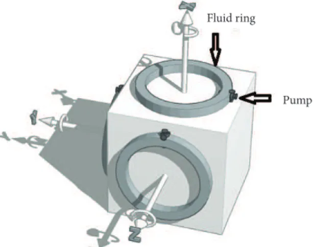
In this section, dynamical model of a rigid satellite containing fluid rings is used to study the performance of attitude determination and control system. The first configuration considered is consisting of three fluid rings in a cube configuration, as shown in Fig. 1. Then as Fig. 2 shows, four fluid rings in a pyramidal configuration. The second configuration is regarded in this approach. Four fluid rings in the pyramidal configuration of a satellite provide a redundant set of servomechanism for the ACS. The results from these simulations will be used in comparison between fluid momentum control and CMG.
Figure 2. Fluid rings in pyramidal configuration of satellite. Figure 1. Fluid rings in cube configuration of satellite.
Fluid ring
Pump
Assumptions include the center of mass of satellite and fluid rings are in geometric center of them, the satellite body coordinate system coincides with the reference coordinate, the fluid viscosity does not change and flow is regarded as incompressible and laminar. The equation of motion of the satellite expressed in body coordinate as Eq. 1 is educed (Nobari and Misra 2012).
where: Mf = Tc – Tftotal moments of fluid motion in the ring.
(1)
s
!
s+
s´
s s+
f=
gg+
dJ. Aerosp. Technol. Manag., São José dos Campos, v10, e4618, 2018 Akbaritabar S; Esmaelzadeh R; Zardashti R
xx/xx 04/14
Substituting Eq. 2 into Eq. 1 gives Eq. 3:
(2)
(3)
(4)
(5)
(6)
(7)
where: Is and If are matrix moment of inertia of satellite and fluid ring, respectively. As shown in Fig. 3, diagonal value If
is obtained from Eq. 4:
where: ρ is fluid density, A and Rl respectively are cross-section and the radius of the ring fluid. The angular velocity and angular acceleration of the fluid is obtained from the following relations (Eq. 5):
According to Eq.5, ρ . and ωs are angular acceleration and velocity matrix of satellite, ρ . and ωfare angular acceleration and velocity matrix of fluid rings in satellite body coordinate, respectively. In addition, β . and β .. i i = 1,2,3 or 4 are angular acceleration and velocity matrix of fluid in ith ring and Tc, Tf, Tggand Tdare respectively control, stress, gravitational gradient and disturbances torques.
At the first, shear stress of the fluid motion with respect to the ring should be calculated to obtain the torque stress Tf, which caused energy dissipation. Therefore, Eq. 6 where σ is shear stress ring fluid and it is obtained for ith ring.
Figure 3. Fluid ring with body coordinate of ring.
In the ring flow taken into account laminar, so Reynolds critical is Rn < 2300 (Eq. 7).
where: f is coefficient of friction. To make it simpler, Eq. 8 Rl >> d is advised. As a result of frictional torque:
fi
!
f+
f´
fi f-
f=
fI
ω ω
I
ω
T
M
´
´
!
!
ω ω
ω
ω ω
ω
T
T
pr
pr
´
! ! ! !
ω ω β ω ω β ω β
´
-!
ω ω
ω
I
sω ω
!
s+
s´
I
sω
s+
I
fiω ω
!
f+
f´
I
fiω
f=
T
f+
T
gg+
T
dpr
pr
´
! ! ! !
ω ω β ω ω β ω β
´
-!
ω ω
ω
´
´
!
!
ω ω
ω
ω ω
ω
3 ,
xi yi l
I =I =prAR
I
zi=
2
pr
AR
l3´
! ! ! !
ω ω β ω ω β ω β
´
-!
ω ω
ω
´
´
!
!
ω ω
ω
ω ω
ω
pr
pr
¨ , s
= + ! ! = ! + + ´ !
f s i f i i
ω ω β ω ω β ω β
ǁ ǁ
×
2 2
1
8 f Rl
s
=r
b
!b p s! p b!
´
!
ω
´
-!
ω
´ !
!
ω ω ω
ǁ ǁ
×
s
r
b
!64
n f
R =
b p s! p b!
´
!
ω
´
-!
ω
´ !
!
J. Aerosp. Technol. Manag., São José dos Campos, v10, e4618, 2018 Design of Attitude Control Servomechanisms with Fluid Ring and CMG for Rigid Satellite
xx/xx 05/14
where: μ is the fluid’s viscosity.
Gravity gradient torque can be calculated from Eq. 9 (Wie 1998):
(8) (9) (10) (11) (12) (14) (13)
where: rc is the vector position of the satellite relative to the Earth.
DYNAMICAL MODELING OF CMG
In this section the rotating equation of motion on rigid satellite (Eq. 10) is derived for momentum exchange actuators such as CMGs. In general given (Wie 1998)
where: HS is the total angular momentum vector of the satellite in body coordinate which gives HS = ISωS + hCMG. Textis the external torque vector on the satellite. Substituting both terms of HSinto Eq. 10 and defining the control torque vector of CMG as Eq. 11, Eq. 10 can be rewritten as Eq. 12.
where: hCMGand are, respectively, angular momentum and torque of CMG as following (Eq. 13):
By following Eq. 14, the rate of rotation angle of the CMG’s gimbal δ . is then obtained.
CONTROLLER DESIGN
Satellite dynamics model and the control torque in a satellite were written for fluid ring and CMG in the previous sections. In this section, the control law equation is analyzed and Euler angle errors as control law are considered for ACS
T
gg = (3n
2/
ǁ
r
c
ǁ
2)r
c×
I
s. r
cs
r
b
!b p s! p b!
´
!
ω
´
-!
ω
´ ! !ω ω ω
ǁ ǁ
×
s
r
b
!b p s! p b!
+
´
=
!
S S S extH
ω
H
T
´
-!
ω
´ !
!
ω ω ω
ǁ ǁ
×
s
r
b
!b p s! p b!
´
!
ω
+
´
=
-!
CMG s CMG ch
ω
h
T
´ !
!
ω ω ω
ǁ ǁ
×
s
r
b
!b p s! p b!
´
!
ω
´
-!
ω
(
)
+! + ´ + = !s s CMG s s s CMG ext
I ω h ω I ω h T
(
)
1 2 3 4
1 2 3 4
1 2 3 4
cos sin cos cos sin cos cos cos sin cos cos sin ,
sin sin sin sin sin
u
d
d
u
d
d
d
u
d
d
u
d
u
d
d
d
d
é- - + + ù
ê ú
=ê - - + ú
ê + + + ú
ë û
CMG h
u d d u d d
d u d d u d
u d u d u d u d
-
-é ù
ê - - - ú
ê ú
ê ú
ë û
! δ! δ!
-! !
δ
j
-
j
j
!
,
- !
q q q
-
!
y
y
y
é ù
é ù
ê ú
é ù ê úê ú
ê ú ê - úê ú
ê ú ê úê ú
ê ú ê úê ú
ê ú ê- úê ú
ê ú ê úê ú
ê ú ê úê ú
ë û ê ú
ê - - úë û
ë û
u
d
d
u
d
d
d
u
d
d
u
d
u
d
d
d
d
é- - ù
ê - - ú
ê ú
ê ú
ë û
1 2 3 4
1 2 3 4
1 2 3 4
cos cos sin cos cos sin
sin cos cos sin cos cos
sin cos sin cos sin cos sin cos
u d d u d d
d u d d u d
u d u d u d u d
-
-é ù
ê ú
= =ê - - - ú
ê ú
ë û
!CMG ! !
h Bδ δ
-! !
δ
j
-
j
j
!
,
- !
q q q
-
!
y
y
y
é ù
é ù
ê ú
é ù ê úê ú
ê ú ê - úê ú
ê ú ê úê ú
ê ú ê úê ú
ê ú ê- úê ú
ê ú ê úê ú
ê ú ê úê ú
ë û ê ú
ê - - úë û
ë û
u
d
d
u
d
d
d
u
d
d
u
d
u
d
d
d
d
é- - ù
ê - - ú
ê ú
ê ú
ë û
u d d u d d
d u d d u d
u d u d u d u d
-
-é ù
ê - - - ú
ê ú
ê ú
ë û
! δ! δ!
(
)
-1 =! T T !
CMG
δ B BB h
j
-
j
j
!
,
- !
q q q
-
!
y
y
y
é ù
é ù
ê ú
é ù ê úê ú
ê ú ê - úê ú
ê ú ê úê ú
ê ú ê úê ú
ê ú ê- úê ú
ê ú ê úê ú
ê ú ê úê ú
ë û ê ú
ê - - úë û
ë û
ǁ ǁ
×
s
r
b
!( )
2 2 2 32 16
f l l
T =sign b p s! R d = p R µb!
´
!
ω
´
-!
ω
´ ! !J. Aerosp. Technol. Manag., São José dos Campos, v10, e4618, 2018 Akbaritabar S; Esmaelzadeh R; Zardashti R
xx/xx 06/14
in three rotation axes. Furthermore, a redundant set of actuators is considered for the ACS to increase reliability and avoid fail in pyramidal configuration.
EULER ANGLE ERRORS CONTROLLER
The magnitude of attitude control torque for each axes of satellite body coordinate is calculated by Euler angle errors vector (Sidi 1997). From Eq. 15 this magnitude is obtained.
(15)
(16)
(17)
(18)
where: Tcx, Tcy and Tcz are control torques about the Xs, Ys, Zs body axes of the satellite, respectively. In order to achieve the desirable response of the system for damping ratio and natural frequency, controller’s coefficients (Kx, Kxd, Ky, Kyd, Kz, Kzd) are obtained by the principles of design of linear control systems.
Required torques about body axes of the satellite are generated. In pyramidal configuration, required torque of each actuator is calculated by Eq. 16. Ti, i = 1,…,4 is torque of each actuator for satellite attitude control and the minimum condition should be applied Δhf = hf1 – hf2 + hf3 – hf4 whereas hfi = Ifi, i = 1,…,4. In addition, the four torques should be converted to principle axes of body coordinate as following Eq. 17. In details, these equations can be defined as (Sidi 1997):
where: the element vector of T ˆc is produced by control law. So that,
and γ is angle between body coordinate of ring and satellite.
u
d
d
u
d
d
d
u
d
d
u
d
u
d
d
d
d
é- - ù
ê - - ú
ê ú
ê ú
ë û
u d d u d d
d u d d u d
u d u d u d u d
-
-é ù
ê - - - ú
ê ú
ê ú
ë û
! δ! δ!
-! ! δ
(
)
,
cx x com xd
T
=
K
j
-
j
+
K
j
!
( ) ,
cy y com yd
T = K q -q +K q!
(
)
cz z com zd
T
=
K
y
-
y
+
K
y
!
é ù
é ù
ê ú
é ù ê úê ú ê ú ê úê ú
-ê ú ê úê ú ê ú ê úê ú ê ú ê- úê ú ê ú ê úê ú ê ú ê úê ú ë û ê ú ê - - úë û
ë û
u
d
d
u
d
d
d
u
d
d
u
d
u
d
d
d
d
é- - ù
ê - - ú
ê ú
ê ú
ë û
u d d u d d
d u d d u d
u d u d u d u d
-
-é ù
ê - - - ú
ê ú
ê ú
ë û
! δ! δ!
-! ! δ
-
!
j
j
j
- !
q q q
-
!
y
y
y
1 2 3 4 1 1 1 0 2 2 1 1 0 1
1 2 2
1 1
2
1 0 0
2 2 1 1 ˆ 0 1 2 2 ˆ ˆ cx cy cz T T T T T T T é ù é ù ê ú
é ù ê úê ú ê ú ê - úê ú ê ú ê úê ú ê ú= ê úê ú ê ú ê- úê ú ê ú ê úê ú ê ú ê úê ú ë û ê ú ê - - úë û
ë û
𝑇𝑇"
#γ
1
2
3
4
1 0 1 0
0 1 0 1
,
1 ˆ
1 1 1
1 1 1
0 ˆ 1 ˆ cx cy cz T T T T T T T é ù
é ù ê ú é - ù
ê ú ê ú ê ú
-ê ú ê ú ê ú
= =
ê ú ê ú ê ú
ê ú ê ú ê ú
ê ú ê ú ë - - û
ë û ë û
f f A A g g g é ù ê ú ê ú é ù ê ú ê ú ê ú ê ú ê ú ê ú ê ú ê ú
ë û ê ú
ê ú
ë û
a
-𝑇𝑇"
#o that
,
a
γ
é ù
é ù ê ú é - ù
ê ú ê ú ê ú
-ê ú ê ú ê ú
ê ú ê ú ê ú
ê ú ê ú ê ú
ê ú ê ú ë - - û
ë û ë û
( )
( )
( )
ˆ ˆ ˆ cx cx cy cy cz cz T sin T T T cos T T cos g g g é ù ê ú ê ú é ù ê ú ê ú ê úê ú=
ê ú
ê ú
ê ú
ê ú
ë û ê ú
ê ú
ë û
-J. Aerosp. Technol. Manag., São José dos Campos, v10, e4618, 2018 Design of Attitude Control Servomechanisms with Fluid Ring and CMG for Rigid Satellite
xx/xx 07/14
Momentum management (Fig. 4) is used to minimize the angular momentum of the four fluids in their rings, detailed information about this approach can be found in (Sidi 1997).
(19)
(20)
(21) Figure 4. Momentum management control of the four fluid rings (Sidi 1997).
NUMERICAL SIMULATION AND RESULTS
The proposed servomechanism of attitude control is based on two types of actuators. They are analyzed in different configurations. At the first, three fluid rings in cube cluster are simulated. Then, four fluid rings in pyramidal cluster are simulated, and simulations results fluid rings and gyros in pyramidal cluster are compared.
Different control performance evaluation methods can be regarded. In suggested control system design, the system attitude is the essential factor in the controller. The saturation is the second factor for demonstration controller. Because of the present friction, the fluid rings will eventually be saturated and the pumps reach their limits, so the fluid angular velocity cannot increase anymore. Therefore, the maximum torque generated by the pump is assumed 3.0 × 10⁻¹ N.m. Moreover,
in this study the robustness of the system against uncertainties is analyzed. Therefore, uncertainty analysis for the satellite momentum of inertia matrix is prepared to study the controller robustness. All simulations in the three case study scenarios are repeated with uncertainty on the inertia matrix IS given by ΔIS = ± 0.3 IS for the proposed linear controller. The forth factor for analysis of control performance is α angle, the amount of angular maneuver about Euler axis of rotation. This parameter can be demonstrated with respect to the initial error matrix AE as (Eq. 19) (Sidi 1997):
where: AE can be found relation to Eq. 20 (Sidi 1997).
The aSandaTare determined with Eq.21.
where: AS is a body coordinate rotation matrix with respect to reference coordinate which is calculated at each time step; AT is a body coordinate rotation matrix with respect to reference coordinate that is calculated when the maneuver is accomplished (the target); a = [a1, a2, a3] is arbitrary vector in reference coordinate.
𝑇𝑇"
#γ
é ù
é ù ê ú é - ù
ê ú ê ú ê ú
-ê ú ê ú ê ú
ê ú ê ú ê ú
ê ú ê ú ê ú
ê ú ê ú ë - - û
ë û ë û
g
g
g
é ù
ê ú
ê ú
é ù
ê ú
ê ú
ê ú
ê ú
ê ú
ê ú
ê ú
ê ú
ë û ê ú
ê ú
ë û
( )
1(
(
)
)
cos trace 1
2 E
a
= A-1 T
S S T T S T T E T
-=
=
=
a
A A
a
A A
a
A a
a
ò
å
-
--
--
-é ´ ´ ù
ê ú
´ ´
ê ú
ê ú
´ ´
ê ú
ë û
-,
S
=
S T=
Ta
A a a
A a
ò
å
-
--
--
-é ´ ´ ù
ê ú
´ ´
ê ú
ê ú
´ ´
ê ú
ë û
Tcx T1 +
+
+
+ +
+
+
+ T2
T3
T4 Sγ
Tcy [A
f] cγ
Tcz cγ
β1
β2
β3
β2 . . . . 1
IfS
∆Tci= [–1]i+1 0.2 ∆hf
1 IfS
1 IfS
J. Aerosp. Technol. Manag., São José dos Campos, v10, e4618, 2018 Akbaritabar S; Esmaelzadeh R; Zardashti R
xx/xx 08/14
According to Eq. 19, the EULERINT (= ∫α dt) is considered criterion factor for analyzing attitude control (Sidi 1997). Control effort is the fifth factor is used to compare two different kinds of actuators for the control performance. The actuators are used to attitude control the satellite dynamic, namely Eq. 22 (Ghadiri et al. 2016):
(22)
(23)
The satellite in a circular orbit with a radius of 21000 km is considered for the simulation results. The matrix elements of the satellite moments of inertia at its center of mass are 𝐼xx = 22.7 kg.m
2, 𝐼
x𝑦 = 0.2 kg.m2, 𝐼𝑥z = 0.5 kg.m 2, 𝐼
𝑦𝑦 = 23.3 kg.m2, 𝐼yz = 0.3 kg.m
2, and 𝐼
𝑧𝑧 = 24.5 kg.m2 (Guo et al. 2016).The fluid rings are mounted on the satellite and their radius and
cross section diameters are 0.2 m and 0.02 m, respectively. These rings are full filled by Propylene Glycol in temperature and pressure are 20 °C and one bar (Nobari 2013). The attitude commands about X, Y and Z reference coordinate axes are based as shown in Table 1. The angles and angular velocities of the satellite are adjusted to zero with the stabilizer control systems. Thus, the initial condition of angles and angular velocities are assumed zero. Further attitude maneuver time is lower than period of this orbit. The proportional and derivative gains of control are Kx = 62.5, Kxd = 125.0, Ky = 31.0, Kyd = 62.5, Kz = 38.0 and Kzd = 120.0. All simulations are carried out with MATLAB/SIMULINK.
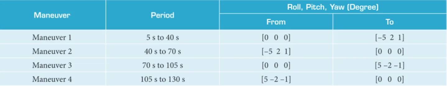
Table 1. Desired maneuver satellite.
Maneuver Period
Roll, Pitch, Yaw (Degree)
From To
Maneuver 1 5 s to 40 s [0 0 0] [–5 2 1]
Maneuver 2 40 s to 70 s [–5 2 1] [0 0 0]
Maneuver 3 70 s to 105 s [0 0 0] [5 –2 –1]
Maneuver 4 105 s to 130 s [5 –2 –1] [0 0 0]
Theses maneuvers are under disturbances torques by following (Eq. 23):
FLUID RINGS IN THE CUBE SATELLITE
A priori assumptions as mentioned earlier. Figure 5a shows the variations of satellite Euler angles before they reach the target angles in each maneuver. As can be seen all of case studies are damped less than 15 s at each maneuver. Figure 5b demonstrates that the maximum fluid angular velocity is a function of moment of inertia. By increasing the moment of inertia in each case, the maximum angular velocity of the fluid is also increased. It is also understood from the Fig. 5b that the attitude maneuver is carried out when the rotational velocities of the fluid became zero. Figure 5c shows that the time responses for the controller are equal: EULERINT = 17.1 deg.sec. along with zero gradient of graph about at each maneuver.
FLUID RINGS IN THE PYRAMIDAL SATELLITE
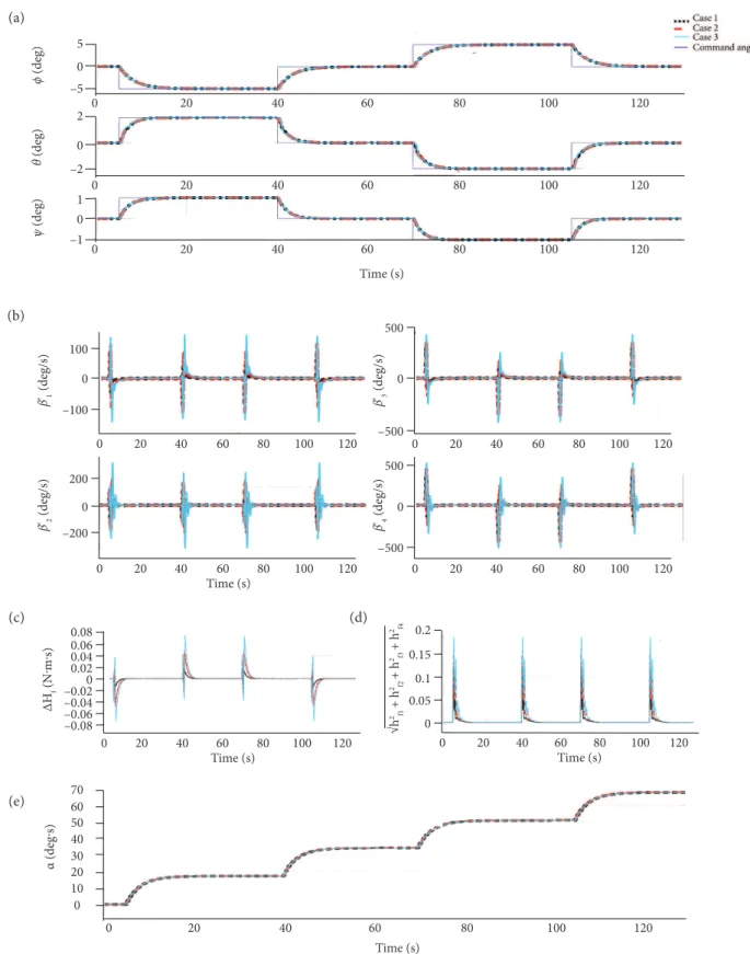
The simulation was conducted and the angle between two body coordinates of satellite and ring γ is 32°. Each torques of the rings is equaled with produced torque based on control law and an addition fluid ring is mounted on the satellite, in which should be used Eqs. 15-17 and momentum management control. As shown in Fig. 6a, the attitude angles of satellite reach the target angles
-4 2
1
i
i
Control Effort T dt
= =
å
ò-
--
--
-é ´ ´ ù
ê ú
´ ´
ê ú
ê ú
´ ´
ê ú
ë û
-ò
å
3 3
3 3
3 3
1 10 sin( ) 1 10
1 10 sin( ) 2 10
1 10 sin( ) 3 10
d
t
t
t
-
--
--
-é ´ + ´ ù
ê ú
=ê ´ + ´ ú
ê ú
´ + ´
ê ú
ë û
T
J. Aerosp. Technol. Manag., São José dos Campos, v10, e4618, 2018 Design of Attitude Control Servomechanisms with Fluid Ring and CMG for Rigid Satellite
xx/xx 09/14
(a)
(b)
(c)
Figure 5. Attitude maneuvering using Euler angle errors in cube configuration. Case1: with ΔJ = –0.3 J (dotted line); Case2: with ΔJ = 0 (nominal case, dash line); Case3: with ΔJ = 0.3 J (solid line). (a) Euler angle versus time, (b) angular velocity versus time, (c) displacement angle during the maneuver versus time.
5 0
ϕ
(deg)
–5
0 20 40 60 80 100 120
Case 1 Case 2 Case 3 Command angle
0 20 40 60 80 100 120
0 20 40 60 80 100 120
Time (s) 2
0
θ
(deg)
–2
1 0
ψ
(deg)
–1
β’1
(deg/s)
0 20 40 60 80 100 120
0 20 40 60 80 100 120
0 20 40 60 80 100 120
Time (s)
β’2
(deg/s)
500 0
β’3
(deg/s)
α
(deg
·s)
–500 500 0
–500 –400 –2000 200 400
0 20 40 60 80 100 120
Time (s) 0
10 20 30 40 50 60 70
J. Aerosp. Technol. Manag., São José dos Campos, v10, e4618, 2018 Akbaritabar S; Esmaelzadeh R; Zardashti R
xx/xx 10/14
ϕ
(deg)
0 20 40 60 80 100 120
–5 0 5
θ
(deg)
0 20 40 60 80 100 120
–2 0 2
ψ
(deg)
0 20 40 60
Time (s)
80 100 120
–1 0 1
α (deg·s)
0 20 40 60 80 100 120
Time (s) Time (s)
0 10 20 30 40 50 60 70
ΔH
f
(N·m·s)
0 20 40 60 80 100 120 –0.08
–0.06 –0.04 –0.020 0.02 0.04 0.06 0.08
Time (s)
β
'2
(deg/s)
0 20 40 60 80 100 120 200
0
–200
β
'1
(deg/s)
0 20 40 60 80 100 120 100
0
–100
Time (s)
0 20 40 60 80 100 120 0
0.05 0.1 0.15 0.2
√h
2 f1
+ h
2 f2
+ h
2 f3
+ h
2 f4
β
'4
(deg/s)
0 20 40 60 80 100 120
β
'3
(deg/s)
0 20 40 60 80 100 120 500
0
–500
500
0
–500
Figure 6. Attitude maneuvering using Euler angle errors in pyramidal configuration. Case1: with ΔJ = –0.3J (dotted line); Case2: with ΔJ = 0 (nominal case, dash line); Case3: with ΔJ = 0.3J (solid line). (a) Euler angle versus time, (b) angular
velocity versus time, (c) minimum condition versus time, (d) norm of angular momentum versus time, (e) displacement angle during the maneuver versus time.
(a)
(b)
(c)
(e)
J. Aerosp. Technol. Manag., São José dos Campos, v10, e4618, 2018 Design of Attitude Control Servomechanisms with Fluid Ring and CMG for Rigid Satellite
xx/xx 11/14
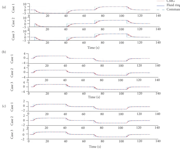
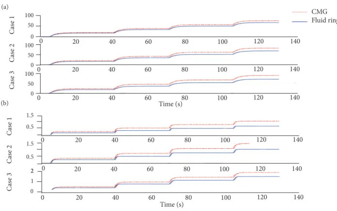
Figure 7. Comparing attitude maneuvering using Euler angle errors for fluid rings and gyros. Case1: with ΔJ = –0.3J; Case2: with ΔJ = zero (nominal case); Case3: with ΔJ = 0.3J. (a) Euler angle versus time about X-axis (ϕ deg), (b) Euler
angle versus time about Y-axis (θ deg), (c) Euler angle versus time about Z-axis (ψ deg).
C
as
e 1
C
as
e 2
C
as
e 3
Time (s)
CMG Fluid ring Command
Time (s)
C
as
e 1
C
as
e 2
C
as
e 3
0 20 40 60 80 100 120 140
0 20 40 60 80 100 120 140
0 20 40 60 80 100 120 140
–2 0 2 –2 0 2 –2 0 2 –4 0 4 –4 0 4 –4 0 4
0 20 40 60 80 100 120 140
0 20 40 60 80 100 120 140
0 20 40 60 80 100 120 140
0 20 40 60 80 100 120 140
0 20 40 60 80 100 120 140
0 20 40 60 80 100 120 140
Time (s)
C
as
e 1
C
as
e 2
C
as
e 3
–5 5 0 10 –5 5 0 10 –5 5 0 10
effective. Figure 6d shows that the moment of inertia is related to damping rotational velocity in the case studies and it demonstrates that the control law is efficient for this configuration. As can be seen in Fig. 6e, the satellite in each case study is conducted with attitude maneuvering control in less than 17 deg.sec.
Compared with three and four rings, maximum angular velocity of the fluid in Fig. 5b has more than maximum angular velocity of the fluid in Fig. 6b for reach to similar attitude command angles.
To prove the assumptions that flow is laminar and incompressible, taking into account the critical Reynolds number Rn = 2300, maximum rotational velocity of the fluid must be 1.8052e + 03 degrees per second. Thus, as can be seen in Figs. 5b and 6b, this limitation is considered exact.
COMPARED WITH CMG
According to simulate assumptions and taking account to υ equals γ, gyros have faster and uniform maneuvers than fluid when they are reached to desired angles, as shown in Fig. 7, in rigid satellite. Whereas the satellite is given stress due to fluid friction with the wall and friction torques for gyro is neglected.
(a)
(b)
J. Aerosp. Technol. Manag., São José dos Campos, v10, e4618, 2018 Akbaritabar S; Esmaelzadeh R; Zardashti R
xx/xx 12/14
Figure 8. Comparing fluid rings and gyros. CMG actuator with red dash dotted line; fluid ring actuator with blue solid line. (a) Displacement angle during the maneuver versus time, (b) control effort versus time.
C
as
e 1
C
as
e 2
C
as
e 3
Time (s)
CMG Fluid ring
0 20 40 60 80 100 120 140
0 20 40 60 80 100 120 140
0 20 40 60 80 100 120 140
0 20 40 60 80 100 120 140
0 20 40 60 80 100 120 140
0 20 40 60 80 100 120 140
Time (s)
C
as
e 1
C
as
e 2
C
as
e 3
0 50 100
0 50 100
0 50 100
1.5 0.5
1.5
0.5
22 1 0
As can be seen in Fig. 8a, both servomechanisms of ACS are damped on less than 15 s and it illustrates fluid servomechanism in all three cases have reached the desired angle with displacement attitude maneuvering less than gyro. Figure 8b illustrates the amount of control effort of required torques with gyros throughout the maneuvers in all three case studies and torque of actuators for fluid rings. Thus, in Fig. 8b fluid ring has less control effort than CMG at four maneuvers.
CONCLUSION
In this work, nonlinear dynamic model of rigid satellites with fluid rings and gyros with all elements of moment of inertia for ACS are obtained. The controller of cube and pyramidal configurations for fluid rings and gyros actuator with Euler angle errors as control law has been presented. Saturation and robustness of the system against uncertainties are regarded with 30% difference on moment of inertia. To achieve the same system response, the maximum rotational velocity of pyramidal cluster with four fluid rings is less than cube cluster with three fluid rings. The equations are solved for laminar flow and it is proved that the flows remain laminar. The performance of satellite natural attitude, amount of attitude maneuver and quantity of control effort are compared in two different types of ACSs for pyramidal cluster. According to results, the fluid rings actuator has less attitude maneuver and less control effort. Nevertheless, servomechanisms should be chosen depending on the mission and requirements.
Fluid ring type of actuator has some limitation. The fluid properties can be affected by environmental pressure and temperature, therefore freezing and boiling.
(a)
J. Aerosp. Technol. Manag., São José dos Campos, v10, e4618, 2018 Design of Attitude Control Servomechanisms with Fluid Ring and CMG for Rigid Satellite
xx/xx 13/14
FUTURE WORK
The suggestions for future work are listed:
• Multidisciplinary design optimization: By using several types of fluid with different properties in a temperature and pressure range, volume and mass of ACS can be optimized.
• Embedding the thermal control system: As mentioned in Conclusion, fluid type of actuator has some limitation in thermal issue. Therefore, the online usage of an observer in passive and active thermal control such as heat radiator, thermostats or heat pipes.
• Contemplate the relations of the fluid and the ring in turbulence flow: Take into account the interaction between the fluid and the ring and vibrations in the ACS in turbulence or laminar flow, it can be shown that it affects the control system.
AUTHOR’S CONTRIBUTION
Conceptualization, Akbaritabar S and Esmaelzadeh R; Methodology, Akbaritabar S; Investigation, Akbaritabar S, Zardashti R and Esmaelzadeh R; Writing – Original Draft, Akbaritabar S, Zardashti R and Esmaelzadeh R; Writing – Review and Editing, Akbaritabar S; Funding Acquisition, Zardashti R and Esmaelzadeh R; Resources, Zardashti R and Esmaelzadeh R; Supervision, Akbaritabar S.
REFERENCES
Abbaspour A, Aboutalebi P, Yen KK, Sargolzaei A (2017) Neural adaptive observer-based sensor and actuator fault detection in nonlinear systems: Application in UAV. ISA transactions 67:317-329. doi: 10.1016/j.isatra.2016.11.005
Nobari NA (2013). Attitude dynamics and control of satellites with fluid ring actuators (PhD Dissertation). Montreal: McGill University.
Ghadiri H, Sadeghi M, Abbaspour A, Esmaelzadeh R (2016) Optimized fuzzy-quaternion attitude control of satellite in large maneuver. Presented at: 14th International Conference on Space Operations; Daejeon, Korea. doi: 10.2514/6.2016-2552
Guo Y, Song S-M, Li X-H (2016) Finite-time output feedback attitude coordination control for formation flying spacecraft without unwinding. Acta Astronautica 122:159-174. doi: 10.1016/j.actaastro.2016.01.015
Iskenderian TC (1989) Liquid angular-momentum compensator. (NPO-17204) NASA Tech Brief.
Jayaram S (2009) Design and analysis of nano momentum wheel for picosatellite attitude control system. Aircraft Engineering and Aerospace Technology 81(5):424-431. doi: 10.1108/00022660910983707
Kawak BJ (2017) Development of a low-cost, low micro-vibration CMG for small agile satellite applications. Acta Astronautica 131:113-122. doi: 10.1016/j.actaastro.2016.10.021
Kelly AC, McChesney C, Smith PZ, Waltena S (2004) A performance test of a fluidic momentum controller in three axes. NASA Technical Report.
Kumar KD (2009) Satellite Attitude Stabilization Using Fuid Rings. Acta Mechanica 208(1-2):117-131. doi: 10.1007/s00707-008-0132-5
Laughlin DR, Sebesta HR, Ckelkamp-Baker D (2002) A dual function magnetohydrodynamic (MHD) device for angular motion measurement and control. Advances in the Astronautical Sciences 111:335-347.
Lurie BJ, Schier JA (1990) Liquid-ring attitude-control system for spacecraft. (NPO-17485) NASA Tech Brief.
Lurie BJ, Schier JA, Iskenderian TC, inventors; NASA, assignee (1991) Fluid-loop reaction system. United States patent US 5026008.
Maynard RS, inventor; NASA, assignee (1988) Fluidic momentum controller. United States patent US 4776541.
J. Aerosp. Technol. Manag., São José dos Campos, v10, e4618, 2018 Akbaritabar S; Esmaelzadeh R; Zardashti R
xx/xx 14/14
Nobari NA, Misra AK (2012) Attitude dynamics and control of satellites with fluid ring actuators. Journal of Guidance, Control, and Dynamics 35(6):1855-1864. doi: 10.2514/1.54599
Haviland RP, inventor; General Electric Co, assignee (1958) Orientation control for a space vehicle. United States patent US 2856142A.
Patel A (2017) Magnetically Levitating Low-Friction Test Stand for the Measurement of Micro-Thruster Performance Characteristics. Presented at: 55th AIAA Aerospace Sciences Meeting; Grapevine, USA. doi: 10.2514/6.2017-2011
Ismail Z, Varatharajoo R, Ajir R, Rafie ASM (2015) Enhanced attitude control structure for small satellites with reaction wheels. Aircraft Engineering and Aerospace Technology 87(6):546-550. doi: 10.1108/AEAT-06-2014-0085
Sadeghi M, Abaspour A, Sadati SH (2015) A novel integrated guidance and control system design in formation flight. Journal of Aerospace Technology and Management 7(4):432-442. doi: 10.5028/jatm.v7i4.473
Shijie GHX (2013) Precise modeling and application of fluidic ring actuator. Chinese Space Science and Technology 3:007.
Sidi MJ (1997) Spacecraft dynamics and control: a practical engineering approach. New York: Cambridge university press.
Tayebi J, Soleymani A (2015) A comparative study of CMG and FMC actuators for Nano satellite attitude control system-pyramidal configuration. Presented at: 7th International Conference on Recent Advances in Space Technologies (RAST); Istanbul, Turkey. doi: 10.1109/RAST.2015.7208370
Varatharajoo R, Fasoulas S (2005) The combined energy and attitude control system for small satellites—Earth observation missions. Acta Astronautica 56(1-2):251-259. doi: 10.1016/j.actaastro.2004.09.027
Wie B (1998) Space vehicle dynamics and control. Reston: AIAA.