ABSTRACT: In this study, an Unscented Kalman Filter (UKF) algorithm is designed for estimating the attitude of a pico-satellite and the in-orbit external disturbance torques. The estimation vector is formed by the satellite’s attitude, angular rates, and the unknown constant components of the external disturbance torques acting on the satellite. The gravity gradient torque, residual magnetic moment, sun radiation pressure and aerodynamic drag are all included in the estimated external disturbance torque vector. The satellite has magnetometers and gyros onboard as the attitude sensors. Because of the inherent nonlinear dynamics and the nonlinear measurement model, the UKF, which is a nonlinear version of the Kalman Filter, is selected as the ilter algorithm. Performance of the proposed algorithm is demonstrated via simulations for a cube pico-satellite and the results are analyzed for different scenarios.
KEYWORDS: Pico-satellite, Attitude estimation, Unscented Kalman ilter, Disturbance torques.
Estimation of Pico-Satellite Attitude
Dynamics and External Torques via
Unscented Kalman Filter
Halil Ersin Söken1, Chingiz Hajiyev2
INTRODUCTION
Although there are numerous researches on cubesats, and this number is increasing day by day, the investigations are still far from being concluded. he Cubesat is basically a cubic pico-satellite which has a volume of 1 liter and mass of no more than 1.3 kg. hese types of satellites are the outcomes of a search for lighter, smaller and cheaper spacecrats, and recently, they have mostly been considered as a part of research projects of organizations like universities (Toorian et al., 2008).
he biggest diiculty of cubesat applications is the limitations on the size and mass of the satellite. All the subsystems must be designed regarding these limitations and, unquestionably, a trade-of between the performance and applicability might be required. Speciically for the attitude determination and control system (ADCS), we cannot use highly accurate sensors and actuators onboard a cubesat, since they are usually heavy and large. he attitude of the satellite must be determined and controlled using miniaturized sensors and actuators, which are usually coarser and less accurate (Candini et al., 2012). In this case, one technique to increase the system performance is to properly select the onboard running ADCS algorithm.
he Extended Kalman Filter (EKF) is a nonlinear Kalman Filter (KF), which has been widely used for satellite attitude estimation (Psiaki et al., 1990; Leferts et al., 1982). On the other hand, the EKF has some disadvantages, especially for the highly nonlinear systems. Generally, this is caused by the mandatory linearization phase of the EKF procedure and so the Jacobians derived with that purpose. For most of the applications, the generation of the Jacobians is time consuming, diicult and
1.Graduate University for Advanced Studies – Sagamihara/Kanagawa – Japan 2.Istanbul Technical University – Istanbul – Turquey
Author for correspondence: Chingiz Hajiyev | Aeronautics and Astronautics Faculty | Istanbul Technical University | Maslak, 34469 Istanbul – Turkey | Email: [email protected]
prone to human errors (Julier and Uhlmann, 2004; Sekhavat
et al., 2007). Nonetheless, the linearization brings about an unstable ilter performance when the time steps for the update is not suiciently small and so the estimation or identiication procedure fails as the ilter diverges (Julier et al., 1995). Per contra, small time steps increases the computational burden because of the larger number of Jacobian calculations. As a result of these facts, the EKF may be eicient only if the system is almost linear on the timescale of update intervals (Julier and Uhlmann, 2004). A relatively new Kalman iltering technique, which does not have the shortcomings of the EKF for the nonlinear systems, is the Unscented Kalman Filter (UKF). he UKF generalizes the Kalman ilter for both the linear and nonlinear systems and, in case of nonlinear dynamics, it provides relatively more accurate estimation results than other known observer design methodologies such as the EKF. he essence of the UKF is the fact that the approximation of a nonlinear distribution is easier than the approximation of a nonlinear function or transformation (Julier et al., 2000). he UKF introduces sigma points for catching higher order statistics of the system. It satisies both better estimation accuracy and convergence characteristics by securing higher order information (Sekhavat et al., 2007). Furthermore, the UKF is more robust against the initial estimation errors, so even in case of inaccurate a priori knowledge about the initial condition of the states, it performs well. he only disadvantage of the UKF is the increase in the computational burden when compared to the EKF. Yet, the computational load depends on the type of application and there are several researches aiming at making the UKF computationally more eicient (Li et al., 2013).
here are many documented studies for the UKF as an estimation algorithm in astronautics. In (Crassidis and Markley, 2003) it is used as a state estimator, while both the states and the parameters of the satellite are estimated by the UKF in Dyke
et al. (2004), Sekhavat et al. (2007) and Sekhavat et al. (2009). Moreover, in Vinther et al. (2011) the UKF is preferred as a part of the inexpensive cubesat attitude estimation method, where also the magnetometer biases are estimated and in Inamori et al. (2009) it is used for in-orbit magnetic disturbance estimation and compensation. In Soken and Hajiyev (2011) and Soken and Sakai (2011), both the magnetometer and the gyro biases are estimated as well as the attitude of the satellite by using the UKF. In Soken and Sakai (2013), two diferent UKFs are run onboard a nanosatellite for attitude estimation, sensor calibration and residual magnetic moment compensation. In Oliveria et al.
(2014), the UKF is used for attitude estimation of a nanosatellite and the results are compared with the EKF. In Li et al. (2013), an adaptive version of the UKF is implemented as a part of the ADCS of a nanosatellite. Lastly, in Cornejo et al. (2010), the UKF is used for state estimation and fault detection purposes within the nanosatellite attitude control system.
In this study, an UKF algorithm is designed for estimating a pico-satellite’s attitude and the in-orbit external disturbance torques acting on the pico-satellite. Gravity-gradient torque, sun pressure, aerodynamic drag and residual magnetic moment are included in the estimated disturbance torque vector. he satellite, for which the algorithm is proposed, has magnetometers and gyros onboard as attitude sensors. he main contribution of this study is to show that it is possible to estimate the unknown external torques as well as the attitude dynamics parameters of the satellite via a simple UKF based algorithm. In addition to the investigations in (Soken and Hajiyev, 2009), a more detailed discussion is given for the torque estimation with an extended simulation scenario. Moreover the case for uncertainty in the satellite’s moments of inertia is covered.
he paper proceeds as follows: the mathematical model of the pico-satellite attitude dynamics is presented in the following section. In “he sensors measurement models” the sensors’ measurement models are given. “Unscented Kalman ilter (UKF) for the estimation of attitude dynamics and external torques” contains information about the UKF algorithm for the attitude state and unknown external torque estimation. In “Simulations”, the performance of the proposed algorithm is demonstrated via simulations. And in the last section of this study, there is a brief summary of the obtained results and the conclusion.
PICO-SATELLITE ATTITUDE
DYNAMICS MATHEMATICAL MODEL
he Euler angles representing the attitude of the satellite (φ is the roll angle about x axis; θ is the pitch angle about y axis; ψ is the yaw angle about z axis), the body angular rates with respect to the inertial axis frame and the constant components of the external disturbance torques form the state vector:
(1)
where
(2)
(3)
ω is the angular velocity vector of the body frame with respect to the inertial frame and Nd is the external disturbance torques vector. Since we only estimate the constant components of the torques in this study:
(4)
he dynamic equations of the satellite can be derived by the use of the angular momentum conservation law (Wertz, 1998):
(5)
where J is the inertia matrix, consisting of the main moments of inertia as J=diag(Jx,Jy,Jz) and Ncis the applied control torque. In this study it is assumed that there is no attitude controller so Nc=0
Kinematic equations of the pico-satellite in terms of Euler angles can be given as:
. (6)
Here, c (.), s (.)and t (.) are the cosine, sine and tangent functions, respectively. Besides, p, q and r are the components of the ωBR vector, which indicates the angular velocity of the body frame with respect to the reference frame (orbit frame). ωBI and ωBRcan be related via:
(7)
where ω0 denotes the angular velocity of the orbit with respect to the inertial frame, found as . A represents the direction cosine matrix (Wertz, 1998):
(8)
THE SENSORS’ MEASUREMENT
MODELS
he investigated cubic pico-satellite has two types of sensors onboard: the magnetometers, which measure the strength of the Earth’s magnetic ield; and the gyros, which provide the angular rates of the satellite with respect to the inertial frame. In this section, measurement models of these two sensors are presented.
THE MAGNETOMETER MEASUREMENT MODEL he Earth magnetic ield vector components can be modeled in the orbit frame as a function of time (Sekhavat et al., 2007):
(9)
(10)
(11)
Here, Meis the magnetic dipole moment of the Earth (Me = 7.943 x 10¹⁵ Wb.m); μ is the the Earth Gravitational constant (μ = 3.98601 x 10¹⁴ m3/s2); i is the orbit inclination; ε
is the magnetic dipole tilt (ε = 11.70); ω
e is the spin rate of the
Earth (ωe = 7.29 x 10⁻⁵rad/s); r
0 is the distance between the centre
of mass of the satellite and the Earth.
(12)
where, H1(t), H2(t) and H3(t) represent Earth’s magnetic field vector components in the orbit frame as a function of time, and Hx (ϕ, θ, ψ, t) Hy (ϕ, θ, ψ, t) and Hx (ϕ, θ, ψ, t) show the measured Earth magnetic ield vector components in the body frame as a function of time and varying attitude. Furthermore, η1 is the zero average Gaussian white noise with the characteristic of
(13)
Here I3x3 is the identity matrix with the dimension of 3 x 3, σmis the standard deviation of each magnetometer error and δkj is the Kronecker delta.
In this study, we assume that the magnetometers are calibrated using either an on-ground or in-orbit technique so no bias terms are included in Eq.(12).
THE GYRO MEASUREMENT MODEL
As aforementioned, the other attitude sensor onboard the satellite is the gyro. Widely used model for the gyro measurements is as follows:
(14)
where,ωBI,meas is the measured angular rates of the satellite, and η2
is the zero mean Gaussian white noise with the characteristic of:
(15)
Here, σvis the standard deviation of each rate gyro random error. Same as the magnetometers, the gyros are assumed to be calibrated.
UNSCENTED KALMAN FILTER (UKF)
FOR THE ESTIMATION OF ATTITUDE
DYNAMICS AND EXTERNAL TORQUES
The essence of the UKF is the unscented transform, a deterministic sampling technique, that we use for obtaining
a minimal set of sample points (or sigma points) from the a priori average and covariance of the states. Then, these sigma points go through nonlinear transformation. The posterior average and the covariance are determined using the transformed sigma points (Julier et al., 1995; Crassidis and Markley, 2003).
he UKF is derived for discrete-time nonlinear equations, so the system model is given by;
(16)
(17)
Here xk is the state vector and is the measurement vector. Moreover wk and vk are the process and measurement error noises, which are assumed to be Gaussian white noise processes with the covariances of Q (k) and R (k) respectively.
he UKF is based on the determination of 2n+1 sigma points with an average of x (k|k) and a covariance of P (k|k). For an n
dimensional state vector, these sigma points are obtained by:
(18)
(19)
(20)
where, x0(k|k), x1(k|k) and x1+n(k|k) are sigma points, n is the state number and k is the scaling parameter which is used for ine tuning, and the heuristic for choosing this parameter is n+k=3 (Julier and Uhlmann, 2004).
corresponds to the lth column of the indicated matrix and l is given as l=1... n.
he next step of the UKF process is transforming each sigma point by the use of system dynamics:
(21)
hen, these transformed values are utilized for gaining the predicted average and covariance (Crassidis and Markley, 2003; Soken and Hajiyev, 2011 )
(22)
l
=1... n
l
=1... n
(23)
Here, is the predicted average and P (k+1|k) is the predicted covariance. Furthermore, the predicted observation vector is:
(24)
where
(25)
Ater that, the observation covariance matrix is determined as:
(26)
where the innovation covariance is
(27)
Here R (k+1) is the measurement noise covariance matrix. On the other hand, the cross correlation matrix can be obtained as:
(28)
he following part is the update phase of the UKF algorithm. At that phase, irst by using measurements, y (k+1), the innovation sequence is found as:
(29)
and then the Kalman gain is computed via the equation:
(30)
At last, the updated states and covariance matrix are determined by:
(31)
(32)
Here, (k+1|k+1) is the estimated state vector, and P (k+1|k+1) is the estimated covariance matrix.
SIMULATIONS
The proposed UKF based estimation method is tested in this section. he simulations are performed for 40,000 s, which is the period for almost 7 orbits of the satellite. he orbit of the cubesat is a circular orbit with an altitude of r=550km
and an inclination of i=97º. he inertia matrix of the satellite is J=diag(2.1x10-3,2.0x10-3,1.9x10-3)kg.m2, which corresponds
to a 10cm cubic satellite with an approximate mass of 1.2kg, as mentioned.
he magnetometer sensor noise is characterized by zero mean Gaussian white noise, with a standard deviation of σm=300 nT.
he rate gyro random error is taken as .
As the ilter parameter for the UKF, ĸ is selected as ĸ=-3, which is diferent than the suggested heuristic.
he initial attitude errors for all the simulations are set to few degrees. he initial estimates for the angular rates and the external disturbance torques are all zero. Besides, the initial value of the covariance matrix is taken as P0=10-10 for all the estimated states, while the process noise covariance matrix is selected as
Q=10-29 for the attitude and Q=10-20 for the rest of the states. he R matrix is composed of the sensor noise covariances for the magnetometers and gyros, which means 9x10-12 T2as 3 diagonal components corresponding to magnetometer measurements and 64 x 10-10 rad2/s2 as 3 diagonal elements corresponding to the gyro measurements. he constant torque term used for modeling purposes in the simulations (the values which will be estimated) is Nd=[5 -3 4]Tx10-1 μNm.
he algorithm was tested in two cases. We are running a dynamics based model for the estimations (in other words, since we are using the satellite dynamics in addition to the kinematics) so there might be uncertainties, mainly caused by the mismatch between the real dynamics and the model used in the ilter. he only source for such uncertainty in our simulations might be the inertia terms, which are not exactly known. Hence the two scenarios for the simulations are the cases with and without the uncertainty in the inertia terms.
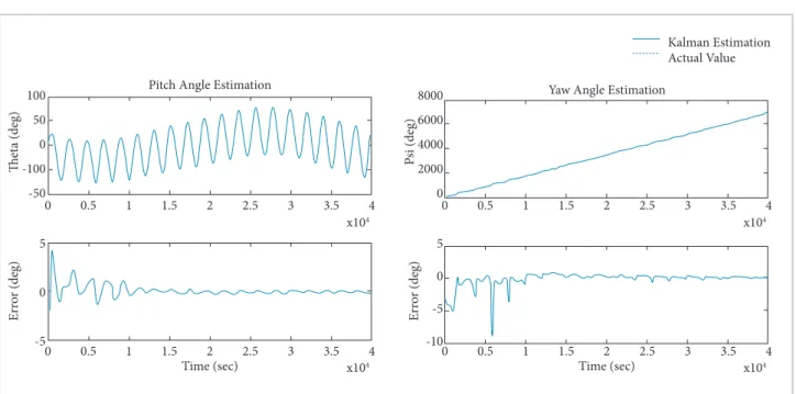
In the irst scenario, there is no uncertainty in inertia terms. In Fig.1, an Euler angle estimation example is given. he top plot compares the estimation with the actual value, and the lower one presents the estimation error. As seen, the UKF accurately estimates the attitude, and ater almost 1.5 orbits (≈11000s.) the estimation error falls below ±1deg. If the attitude determination accuracy requirement for such pico-satellite without attitude control is considered (±1deg of determination accuracy may be accepted as suicient), then we may state that the UKF algorithm works well and provides suicient accuracy for pico-satellite missions. Besides, as presented in Fig. 2, the UKF also has a good estimation characteristic for the angular rates.
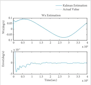
As to the main purpose of the proposed algorithm, the Fig. 3 presents an example for the estimation of the external disturbance torques. As clearly seen, the UKF converges to the real values ater 10,000th s, and gives suiciently accurate estimations for the torque terms. herefore, we can say that the given UKF algorithm estimates all of the states accurately. he estimation results for the rest of the parameters are similar and can be seen in Figs. 4-6. he key contribution of the method is proving that such estimation can be achieved by a simple algorithm that is computationally nondemanding and eicient enough for cubesat applications.
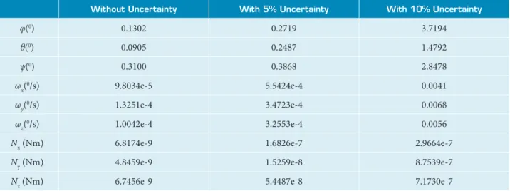
The second simulation is performed for a scenario where we do not know the inertia of the satellite accurately, and there are 5% and 10% uncertainty in inertia terms, respectively. For understanding sake, the results are given in table with comparison with the results obtained for the
0.5
0 1 1.5 2 2.5 3 3.5 4
x 104
x 104
- 100 -50 0 50 100 Ph i( d eg )
Roll Angle Estimation
Kalman Estimation Actual Value
0 0.5 1 1.5 2 2.5 3 3.5 4
0 5 -5 10 Er ro r( d eg ) Time(sec)
Figure 1. Roll angle estimation.
0.1 -0.05 0 0.05 0.1 W x( d eg /s ) Wx Estimation Kalman Estimation Actual Value
0 0.5 1 1.5 2 2.5 3 3.5 4
x 104
-5 0 5x 10⁻³
Er ro r( d eg /s ) Time(sec)
0 0.5 1 1.5 2 2.5 3 3.5 4
x 104
Figure 2. Estimation of the angular velocity about “x” axis.
-10 -5 0 5 N y( N m ) Ny Estimation Kalman Estimation Actual Value 0.5
0 1 1.5 2 2.5 3 3.5 4
x 104
0.5
0 1 1.5 2 2.5 3 3.5 4
x 104
-10 -5
0
5x 10
-7
x 10-7
Er ro r( Nm ) Time(sec)
first scenario, beforehand. In Table 1, root mean square errors are tabulated for 10,000 s. between 20,000th and 30,000th seconds such that;
(33)
Pitch Angle Estimation
h
et
a (deg)
P
si (deg)
Er
ro
r (deg)
Er
ro
r (deg)
Time (sec)
0 0.5 1 1.5 2 2.5 3 3.5
x104
4
Time (sec)
0 0.5 1 1.5 2 2.5 3 3.5
x104
x104 x104
4 0
100
50
0
-100
-50
8000
6000
4000
2000
0
5
0
-5
5
0
-5
-10
0.5 1 1.5 2 2.5 3 3.5 4 0 0.5 1 1.5 2 2.5 3 3.5 4
Yaw Angle Estimation
Kalman Estimation Actual Value
As it can be seen, even for a small uncertainty in inertia terms of the satellite, the estimation error increases for all the estimated states. Yet, for the simulation case with 5% uncertainty, estimation error is still within the acceptable bounds for cubesat applications, regarding that the attitude estimation accuracy is better than ±1deg. However, if the level of uncertainty is 10%,
Figure 4. Estimation of the pitch and yaw angles.
Figure 5. Estimation of the angular velocities about “y” and “z” axes.
Wy Estimation
W
y (deg/s)
Wz (deg/s)
Er
ro
r (deg/s)
Er
ro
r (deg/s)
Time (sec)
0 0.5 1 1.5 2 2.5 3 3.5
x104
4
Time (sec)
0 0.5 1 1.5 2 2.5 3 3.5
x104
x104
x10-3 x10-3 x10
4
4 0
0.2
0.1
0
-0.1
-0.2
0.2
0.15
0.1
0.05
0
5
0
-5
2
0
1
-1
-2
0.5 1 1.5 2 2.5 3 3.5 4 0 0.5 1 1.5 2 2.5 3 3.5 4
Wz Estimation
Table 1. Root mean square error for the cases with and without uncertainty in the inertia terms of the satellite.
Without Uncertainty With 5% Uncertainty With 10% Uncertainty
φ(0) 0.1302 0.2719 3.7194
θ(0) 0.0905 0.2487 1.4792
ψ(0) 0.3100 0.3868 2.8478
ωx(0/s) 9.8034e-5 5.5424e-4 0.0041
ωy(0/s) 1.3251e-4 3.4723e-4 0.0068
ωz(0/s) 1.0042e-4 3.2553e-4 0.0056
Nx (Nm) 6.8174e-9 1.6826e-7 2.9664e-7
Ny (Nm) 4.8459e-9 1.5259e-8 8.7539e-7
Nz (Nm) 6.7456e-9 5.4487e-8 7.1730e-7
Nx Estimation
N
x (N
m)
N
z (N
m)
Er
ro
r (N
m)
Er
ro
r (N
m)
Time (sec)
0 0.5 1 1.5 2 2.5 3 3.5
x104 4
Time (sec)
0 0.5 1 1.5 2 2.5 3 3.5
x104 x104
x10-6 x10-6
x10-6 x10-6
x104
4 0
1 0.5 0 -0.5 -1
1
0.5
0
5
0
-5
-10
1 0.5 0 -0.5 -1
0.5 1 1.5 2 2.5 3 3.5 4 0 0.5 1 1.5 2 2.5 3 3.5 4
Nz estimation
Kalman Estimation Actual Value
Figure 6. Estimation of the constant external torques about “x” and “z” axes.
then it is not possible to satisfy these requirements and the attitude estimation error becomes more than ±1deg. Further examinations show that if there is even more uncertainty in the inertia terms of the satellite, the ilter may diverge in long term.
CONCLUSION
In this study, an Unscented Kalman Filter (UKF) algorithm is designed for estimating a pico-satellite’s attitude and the in-orbit external disturbance torques acting on the pico-satellite. he gravity-gradient torque, sun pressure, aerodynamic drag and residual
REFERENCES
Candini, G.P., Piergentili, F. and Santoni, F., 2012, “Miniaturized Attitude Control System for Nanosatellites”, Acta Astronautica, Vol. 81, pp.325-334. doi: 10.1016/j.actaastro.2012.07.027.
Cornejo, N.E., Amini, R. and Gaydadjiev, G., 2010, “Model-based Fault Detection for the DELFI-N3XT Attitude Determination System”, Proceedings of 2010 IEEE Aerospace Conference, Montana, USA, pp. 1-8. doi: 10.1109/AERO.2010.5446801.
Crassidis, J.L. and Markley, F.L., 2003, “Unscented Filtering for Spacecraft Attitude Estimation”, Journal of Guidance, Control, and Dynamics, Vol. 26, pp. 536-542. doi: 10.2514/2.5102.
Dyke, M.C., Schwartz, J.L. and Hall, C.D., 2004, “Unscented Kalman Filtering for Spacecraft Attitude State and Paremeter Estimation”, Proceedings of the AAD/AIAA Space Flight Mechanics Conference, No. AAS 04-115, Hawaii, USA.
Inamori, T., Nakasuka, S. and Sako, N., 2009, “In-orbit Magnetic Disturbance Estimation and Compansation Using UKF in Nano-Satellite Mission”, Proceedings of AIAA Guidance, Navigation, and Control Conference, Chicago, USA.
Julier, S.J. and Uhlmann, J.K., 2004, “Unscented Filtering and Nonlinear Estimation”, Proccedings of IEEE, Vol. 92, No. 3, pp. 401-422. doi: 10.1109/JPROC.2003.823141.
Julier, S.J., Uhlmann, J.K. and Durrant-Whyte, H.F., 1995, “A New Approach for Filtering Nonlinear Systems”, Proceedings of American Control Conference, Vol.3, pp. 1628-1632. doi: 10.1109/ ACC.1995.529783.
Julier,S., Uhlmann, J. and Durrant-Whyte, H.F., 2000, “A New Method for the Nonlinear Transformation of Means and Covariances in Filters and Estimators”, IEEE Transactions on Automatic Control, Vol.45, No. 3, pp. 477-482. doi: 10.1109/9.847726 .
Lefferts, E.J., Markley, F.L. and Shuster, M.D., 1982, “Kalman Filtering for Spacecraft Attitude Estimation”, Journal of Guidance, Control, and Dynamics, Vol.5, pp. 417-429. doi: 10.2514/3.56190.
Li, J., Post, M.A. and Lee, R., 2013, “A Novel Adaptive Unscented Kalman Filter Attitude Estimation and Control Systems for 3U Nanosatellite”, Proceedings of European Control Conference, Zurich, Switzerland, pp.2128-2133.
Oliveira, G.F., Nehme, P.H.D. and Cappelletti, C., 2014, “Analysis and Simulation of Attitude Determination and Control for the Serpens
Nanosatellite,” Proceedings of 2nd IAA Conference on Dynamics and
Control of Space Systems, Rome, Italy, pp.1-20.
Psiaki, M.L., Martel, F. and Pal, P.K., 1990, “Three-axis Attitude Determination via Kalman Filtering of Magnetometer Data”, Journal of Guidance, Control, and Dynamics, Vol.13, pp. 506-514. doi: 10.2514/3.25364.
Sekhavat, P., Gong, Q. and Ross, I.M., 2007, “NPSAT I parameter Estimation Using Unscented Kalman Filter”, Proceedings of 2007 American Control Conference, New York, pp. 4445-4451.
Sekhavat, P., Karpenko, M. and Ross, I.M., 2009, “UKF-Based Spacecraft Parameter Estimation Using Optimal Excitation”, Proceedings of AIAA Guidance, Navigation and Control Conference, Chicago, USA.
Soken, H.E. and Hajiyev, C., 2009, “UKF for Identiication of the Pico-Satellite Attitude Dynamics Parameters and External Torques on IMU and Magnetometer Measurements”, Proceedings of 4th International Conference on Recent Advances in Space Technologies, Istanbul, Turkey, pp. 541 – 546. doi: 10.1109/RAST.2009.5158254
Soken, H.E. and Hajiyev, C., 2011, “In-light Calibration of Pico Satellite Attitude Sensors Via Unscented Kalman Filter”, Gyroscopy and Navigation, Vol.2, No.3, pp.156-163. doi: 10.1134/S2075108711030114.
Soken, H.E and Sakai, S., 2011, “UKF Based On-Orbit Gyro and Magnetometer Bias Estimation as a Part of the Attitude Determination Procedure for a Small Satellite”, Proceedings of 11th International Conference on Control, Automation and Systems, Seoul, Korea, pp. 1891-1896.
Soken, H.E. and Sakai, S., 2013, “A Study on an Accurate yet Simple
Attitude Estimation Scheme for Nanosatellites”, Proceedings of 5th
Nano-satellite Symposium, Tokyo, Japan, pp.1-21.
Toorian, A. Diaz, K. and Lee, S., 2008, “The Cubesat Approach to Space Access”, Proceedings of 2008 IEEE Aerosacpe Conference, Montana, USA, pp. 1-14. doi: 10.1109/AERO.2008.4526293.
Vinther, K., Jensen, K.F., Larsen, J.A. and Wisniewski, R., 2011, “Inexpensive Cubesat Attitude Estimation Using Quaternions and Unscented Kalman iltering”, Automatic Control in Aerospace, Vol. 4, No. 1.