ABSTRACT: Because they are inexpensive platforms for satellites, CubeSats have become a low-cost way for universities and even developing countries to have access to space technology. This paper presents the ITASAT design, particularly the Attitude Determination and Control Subsystem, the Onboard Software, and the Assembly, Integration and Testing program. The ITASAT is a 6U CubeSat nano-satellite in development at the Instituto Tecnológico de Aeronáutica, in São José dos Campos, Brazil. The platform and its subsystems will be provided by industry while the payloads are being designed and developed by the principal investigators. The ITASAT Attitude Determination and Control Subsystem will rely on a 3-axis magnetometer, 6 analog cosine sun sensors, 3-axis MEMS gyroscopes, 3 magnetic torque coils, and 3 reaction wheels. The Attitude Determination and Control Subsystem operating modes, control laws, and embedded software are under the responsibility of the Instituto Tecnológico de Aeronáutica. A Kalman ilter shall be employed to estimate the quaternion attitude and gyroscope biases from sensor measurements. The Attitude Determination and Control Subsystem operating modes are the nominal mode, with geocentric pointing attitude control and the stabilization mode, in which only the satellite angular velocity is controlled. The nominal mode will be split into 2 sub-modes: reaction wheel control plus magnetic wheel de-saturation and 3-axis magnetic attitude control. Simulation results have shown that the attitude can be controlled with 1-degree accuracy in nominal mode with the reaction wheels, but these errors grow as much as 20 degrees or higher with the 3-axis magnetic control.
KEYWORDS: Satellite attitude control, CubeSat, Attitude determination, Kalman ilter.
The ITASAT CubeSat Development and Design
Valdemir Carrara1,2, Rafael Barbosa Januzi3, Daniel Hideaki Makita4, Luis Felipe de Paula Santos5, Lidia Shibuya Sato5
INTRODUCTION
CubeSat platforms use Commercial Of-he-Shelf (COTS) components that cost tenths of the expensive radiation-resistant and space qualiied components. One of the greatest advantages of these nano-satellites is the possibility of using them as technological development platforms, in which new equipment, new ideas, and new concepts can be tested, qualiied and optimized before going through the high reliability commercial systems. his technology is ready to develop and to perform in orbit testing of sensors, actuators, and control logic at low cost for the Attitude Determination Control System (ADCS) of CubeSats. With few adaptations, control logics can be integrated to large satellites, with the advantage of already having been qualiied in light. Brazil has placed 3 CubeSats platforms in orbit, all of them with passive attitude stabilization, without active control. Four CubeSats are under development, and these should have 3-axis autonomous attitude stabilization and control.
As a recent technology, there are still few publications concerning CubeSats attitude stabilization and control. In recent years, however, several space missions based on nano-satellites have been launched, with some of them with onboard active attitude control. Vega et al. (2009), for instance, showed a magnetic actuation system for precession control of a 3U spin stabilized CubeSat, with magnetometer and coarse sun sensors for attitude determination. Li et al. (2013) describe the design of an ADCS for CubeSat, with a non-linear fuzzy controller (Adaptive Fuzzy Sliding Magnetic Control) based on reaction wheels, which showed superior performance for a conventional Proportional, Integral
1.Instituto Nacional de Pesquisas Espaciais – Engenharia e Tecnologias Espaciais – Divisão de Mecânica Espacial e Controle – São José dos Campos/SP – Brazil. 2.Departamento de Ciência e Tecnologia Aeroespacial – Instituto Tecnológico de Aeronáutica – Divisão de Engenharia Aeronáutica – São José dos Campos/SP – Brazil. 3.Universidade Federal de São Paulo - Instituto de Ciência e Tecnologia - Departamento de Ciência da Computação – São José dos Campos/SP – Brazil. 4.Universidade Federal de São Paulo - Instituto de Ciência e Tecnologia - Departamento de Engenharia da Computação – São José dos Campos/SP – Brazil. 5.Departamento de Ciência e Tecnologia Aeroespacial – Instituto Tecnológico de Aeronáutica – Divisão de Engenharia Eletrônica e Computação – São José dos Campos/SP – Brazil.
and Derivative (PID) controller in simulation. Oluwatosin et al.
(2013) demonstrate the stability of an attitude control for CubeSat using 4 reaction wheels with quaternion feedback error. Babcock and Bretl (2011) suggested a Kalman ilter with state supplied by the truncated quaternion, as originally formulated by Leferts
et al. (1982). hey applied the ilter for the attitude estimation process of a CubeSat, with vectors provided by a magnetometer and coarse sun sensors based on current generated in the solar panels. A similar procedure was employed by Vinther et al.
(2011) to estimate the attitude of a CubeSat with an Unscented Kalman Filter whose state was deined by the attitude quaternion and angular rate. To get rid of the singularity in the covariance matrix, that authors utilized the delta-quaternion, as formulated by Leferts et al. (1982). In a thorough job, Quadrino (2014) presented the ADCS design and testing plan for the MicroMas CubeSat. his satellite employs 6 coarse sun sensors, 4 infrared horizon sensors, an Inertial Measurement Unit (IMU) with a 3-axis magnetometer, an accelerometer, and a 3-axis gyroscope. Attitude determination is performed by a TRIAD algorithm (Black 1964), together with an algorithm that selects the best combination of 2 vectors from the 3 sensors. A Kalman ilter based on the study of Leferts et al. (1982), with state given by the reduced quaternion (obtained by TRIAD), estimates and ilters the attitude quaternion and the gyroscope bias. he MicroMas attitude control is performed by a set of three reaction wheels and three magnetic torquers.
Attitude control by purely magnetic means faces 2 major problems: the generated torque is always perpendicular to the direction of Earth’s magnetic ield, and the magnitude of the torque varies with the orbital position of the satellite. Both prevent the linear control theory to be applied in proving the attitude stability. Due to this reason, several studies have been proposed to demonstrate the stability of purely magnetic controllers with state feedback (Byrnest and Isidori 1991; Lovera and Astoli 2004), with or without attitude determination (Bushenkov
et al. 2002). Silani and Lovera (2005) adopt an H∞periodic controller to demonstrate the stability of the magnetic control, and Psiaki (2001) describes a purely magnetic control that uses a periodically asymptotic linear quadratic regulator.
he ITASAT shall be placed in a sun-synchronous low altitude circular orbit, around 600 km, with 97° inclination. Launch campaign is scheduled to last from March till May 2017. he main payload is a transponder that receives and transmits environmental data collected by autonomously operated platforms on ground. he ITASAT satellite is based on a CubeSat
architecture with 6U shape, arranged in a matrix of 3 × 2 cubic units, with mass around 4.5 kg. he ITASAT bus was acquired from industry, including the Power, Telemetry, Tracking and Command (TT&C), OnBoard Computer (OBC) subsystems, and ADCS components. he main objective of this paper is to present the current status of the ITASAT design, particularly on the Assembly, Integration and Testing (AIT) program and the ADCS, which is the most complex subsystem on the satellite. Although the ADCS components were bought from CubeSat industry, the control logic, attitude determination, and operating modes shall be developed by an in-house program. Attitude determination is based on 2 vector measurements, provided by a 3-axis magnetometer and coarse sun sensors (CSS). Angular rate will be achieved by a set of MEMS gyroscopes. he magnetometer and gyroscope signals are digitally acquired by a microprocessor and transferred to the OBC by an I2C interface,
which also reads the CSS and computes the control logic. he OBC board comprises also a second magnetometer. his paper describes the ADCS design of ITASAT, together with details of the TT&C sotware architecture and the AIT plan. Some results from attitude simulation of the ITASAT in each operating mode will be shown, together with the eforts that were carried out to accomplish the requirements for the mission. Currently the light model is already ready to be launched, although some minor changes in the light sotware are still to be made. Next section will present the ADCS subsystem, the ITASAT operating modes, and the simulation results. In sequence the Onboard Sotware design and the AIT program design will be presented.
ATTITUDE DETERMINATION AND CONTROL SUBSYSTEM
he ITASAT attitude was speciied to be 3-axis stabilized with the yaw axis (x-axis) pointing towards the zenith, as shown in Fig. 1. he z-axis shall remain aligned to the orbit angular
Figure 1. ITASAT CubeSat body-ixed axes: x is yaw, y is roll, and z is pitch.
x
y
z Earth
momentum, perpendicular to the orbit plane. he y-axis (roll) completes the body-ixed frame, aligned to the satellite velocity vector. Although there is no requirement to align both the roll and pitch axes with the orbit velocity vector and angular momentum, attitude stability is achieved only when the axis of the largest moment of inertia, that is, the z-axis remains aligned to the normal of the orbit plane. he body-ixed frame yaw-roll-pitch is parallel to the orbit frame x-y-z when the satellite pointing error is null.
Attitude determination relies on a set of 5 coarse analog sun sensors (CSS) on each satellite side, except the face pointing to Earth, where there is no sensor, together with a 3-axis magnetometer (MAG) and a 3-axis MEMS gyroscope (GYR). Attitude control is achieved by means of a set of 3 magnetic torque coils (MT), 2 of which uses a magnetic core material and one is an air core coil, and 3 reaction wheels (RW). All sensors and actuators have their axes aligned to the satellite axes.
here are no restrictions concerning the attitude pointing error and determination accuracy. However, since one of the payloads is a camera, it was established that a pointing error below 15 degrees is acceptable. Requirement on the attitude stability is more restringing, actually, and shall be better than 0.06o/s in order to guarantee a sharp picture. his is not an easy
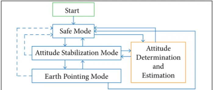
task, since MEMS gyroscope outputs barely reach this magnitude. To fulill the control requirements, four attitude control modes were envisaged. Just ater orbit injection and starting the onboard computer, the satellite automatically enters in Safe Mode (SM), in which no actions for attitude control are taken. his mode allows ground commands and sends onboard telemetry; however, sensors and actuators are switched of. By ground command the SM can be switched to Attitude Stabilization mode (ASM) or alternatively to the Attitude Determination and Estimation mode (ADE), as shown in Fig. 2. In fact, the ADE is not a real operating mode, since the computations for attitude determination and estimation are also done in all modes, except the SM. It is considered a true mode due to the
necessity of attitude knowledge even when the attitude is not being stabilized or controlled. Moreover, by checking the attitude determination error from telemetry (by means of the ilter residue, for instance), the Earth Pointing Mode (EPM) can be activated without taking risk of instability in the attitude control. In Fig. 2, the illed lines represent ground commands while the dotted lines mean autonomous reconiguration onboard commands.
In Attitude Determination and Estimation the procedures to perform both attitude determination and estimation, as explained in next section, will be carried out. he attitude knowledge will be further used in Earth Pointing Mode to properly point the satellite to Earth. However, in the ADE mode only, all the actuators are switched of and no actions on attitude control are done. Two conditions are needed to allow EPM command: the attitude shall be known with high conidence and the satellite angular rate shall be small. he irst condition is acquired by the ADE mode and last condition is achieved by the ASM mode. In the ASM the satellite angular rate shall be damped till a maximum speciied value of 0.6o/s ≈ 0.01 rad/s in any
axis. his low rate assures the necessary condition for entrance in the three-axis attitude control mode (EPM), since a large angular momentum of the satellite could saturate the reaction wheels. Two diferent algorithms shall be implemented to ASM mode: the B-dot algorithm (Bushenkov et al. 2002), and a Rate Reduction mode (RR), similar to the B-dot but based on gyro measurements instead of the Magnetometer time derivative.
he EPM aims to point the negative x-axis to Earth and to keep the angular rate below the speciied value. Again, 2 types of control laws were implemented in the onboard computer. he irst one employs a Reaction Wheel Controller (RWC) with a conventional PID with gains adjusted to drive the reaction wheels whenever an attitude pointing error is detected. he angular rate is also adjusted to track the orbital rate, around 0.06os, so as to keep the right attitude when the satellite travels
its orbit. Reaction wheel speed will be damped by means of magnetic torques, provided by the MT, in order to maintain the RW rate in a safe range. he second control law is a 3-axis Magnetic Torque Controller (MTC), which also uses a control based PID exclusively on the magnetic torque coils to drive the satellite attitude. Due to the small torque provided by this type of actuator, it is expected that the attitude error will be larger than the previous controller with the RW. Moreover, the inability of the MT to generate torques in 3 axes can jeopardize this type of control, and makes gain adjusting a real hard job. hese 2 types of controller are needed due to the energy
Attitude Stabilization Mode
Earth Pointing Mode Start
Safe Mode
Attitude Determination
and Estimation
CSS Sun model
Kalman
filter Sun vector
RTC
GYR
Julian date Day time
Shadow
IGRF Earth coordinates
B inertial SGP4
MAG
LP filter
LP filter ADE TLE
q, ω
restrictions for operating the RW during the whole orbit. From the EPM the satellite can be commanded to enter in any of the remaining attitude operating modes by ground command or in the SM by the autonomous reconiguration command, which employs speciic algorithms to detect attitude anomalies. hese anomalies are then analyzed by the on-ground specialists and actions are taken in order to overcome the problem, if any. Figure 3 illustrates the entrance condition and stability range of each operating mode and control algorithm, as function of the satellite’s angular rate. As seem in this igure, either the B-dot or the RR can manage to drive the angular rate to a condition that enables the EPM operation with the reaction wheels (RWC). Although the MTC has a large operating range, in terms of angular rate, it lacks controllability in low velocities. he next sections will present respectively the ADE, the ASM, and the EPM algorithms for ITASAT.
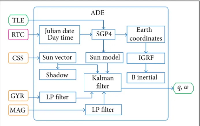
the geomagnetic ield rotates together with the Earth, the model computes the ield strength in Earth centered coordinates as function of the geocentric latitude, longitude and altitude (or the radius from Earth’s center) of the true satellite position in its orbit. herefore the satellite orbit shall also be onboard propagated to feed the geomagnetic ield with proper data. he SGP4 (Hoots and Roehrich 1980) analytical orbit propagator will be used to compute the satellite inertial position, whereas the geomagnetic field will be calculated by the International Geomagnetic Reference Field (IGRF) model (International Association of Geomagnetism and Aeronomy 2015). he SGP4 takes as input the Two Line Elements (TLE) provided by NORAD (Kelso 2015), with 2 days delay, normally. Figure 4 shows a simpliied block diagram of the ADE mode for attitude estimation with Kalman ilter, which estimates the inertial attitude quaternion, q, and the gyroscope biases, b. he angular rate ω is computed by a low pass ilter applied to the gyro measures compensated from the biases. he remaining attitude determination methods follow similar procedures. Care must be taken when the satellite is in the Earth’s shadow, due to the unavailability of CSS data. he time and date necessary for computations are provided by an onboard real time clock (RTC). he complete ilter model and equations can be found in Carrara (2016) as well as the control laws for the operating modes, except for the Attitude Stabilization Mode, whose control law will be presented in next section. It is assumed that a prior on ground calibration of the magnetometer was carried out, so the expected in orbit magnetometer bias is negligible (Amorim and Martins Filho 2016).
0.0001 0.001 0.01 0.1 1
rad/s Orbit injection B-dot
RR RW + MWD
MTC Orbital rate
ω
Figure 3. Entrance condition for each operating mode and control algorithm as function of the angular rate.
ADE MODE
he ADE algorithm employs 2 methods do compute the satellite attitude: the TRIAD (Black 1964; Markley 1998; Markley and Crassidis 2014), or QUEST (Shuster and Oh 1981), alternatively, and a Kalman ilter with reduced order covariance matrix (Leferts et al. 1982), or with incremental quaternion (Garcia et al. 2016). Alternatively the Kalman ilter can estimate not only the attitude, but also the disturbance torques (Söken and Hajiyev 2014). Either a low pass ilter (LPF) on the gyroscope measurements or a numeric derivative of the attitude can be employed to compute the satellite angular rate, and since the attitude can be estimated by several methods, the number of combinations to compute the attitude and rate is high. Attitude determination is performed with 2 vectors attitude determination algorithms, based on the magnetometer and solar sensor readings, which needs also knowing these vectors in a reference frame, normally the inertial or the orbital frame. For ITASAT these reference vectors are computed by the onboard computer based on numeric models of the geomagnetic ield and the Sun’s direction in inertial coordinates. However, since
Figure 4. Simpliied block diagram of the Attitude Determination and Estimation mode.
ATTITUDE STABILIZATION MODE
0.04 rpm, which is 4 times larger than the controlled rate in EPM. As mentioned before, 2 methods will be implemented; each can be selected by ground command. he B-dot algorithm employs the time derivative of the Earth’s magnetic field as measured by the magnetometer to generate a torque by the magnetic coils that tries to break the satellite. Since the magnetic torque is given by the cross product between the coil magnetic moment and the Earth’s ield strength, as
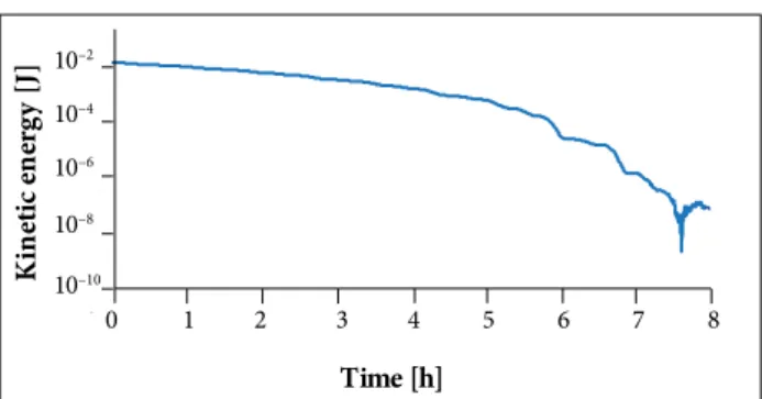
is achieved in less than 6 h ater orbit injection. It was adopted in simulation a sun-synchronous orbit at 630 km altitude, and the sensors were modeled with Gaussian noise and bias compatible with the information provided by the supplier. A constant residual magnetic moment of 0.001 Am2 magnitude on the satellite was
considered as a single perturbation on attitude. A maximum dipole of 0.04 Am2 (20% of the maximum available) in each
magnetic torque coil was adopted to avoid fast control action, which could destabilize the attitude. Considering the expected satellite inertia, the kinetic rotational energy corresponding to the maximum angular rate of 0.01 rad/s is around 5 μJ. he simulated kinetic energy ater orbit injection is shown in Fig. 5. he stability condition is achieved ater 7 h.
so the magnetic moment vector can be obtained by
(1)
(3)
(4) (2)
and remembering that by the time derivative of a vector in a rotating frame is such that
where the subscripts i and b mean the derivative taken in the inertial and body ixed frames, respectively, it results, ater substituting Eqs. 3 and 2 in Eq. 1,
considering, of course, that Ḃ|i « Ḃ|b and therefore Ḃ|ican be
neglected. he magnetic torque is opposed to the component of the angular rate perpendicular to the magnetic ield B, and can decrease this component. Even considering that the component of ω in the direction of B can not be reduced, it will always be possible to generate torque in three-axis, although not at same time, since B changes slowly as the satellite travels its orbit.
he Rate Reduction algorithm is similar to the B-dot, except that it takes directly the satellite’s angular rate as measured by the gyroscope, instead of the time derivative of the geomagnetic ield, to compute the magnetic moment to be applied to the MT:
EARTH POINTING MODE
he EPM aims to point the satellite axis to Earth and to keep the angular rate closed to the speciied value. Due to limitations on the energy available for the ADCS, the reaction wheels can not be operated the whole orbit. So it is necessary to switch between the 2 control laws of the EPM whenever the satellite needs ine Earth pointing to acquire pictures, for instance. his can be done only when the satellite is in contact with mission center, located in São José dos Campos, Brazil. For the remaining of the orbit 3-axis magnetic attitude stabilization and control will be employed. he control laws and the simulated results are shown in sequence.
EPM with Reaction Wheel Control
When in ine pointing mode, the wheel’s speeds need to be damped by a magnetic control law. he block diagram of the RW control is shown in Fig. 6. he RW controller, CRW, computes the attitude error in Euler angles from the attitude quaternion q with respect to the reference attitude, besides the satellite angular velocity with respect to the orbital frame, and (5)
Both modes were simulated in MATLAB with the PROPAT Toolbox (Carrara 2015), and gave similar results. he B-dot simulation is shown in Fig. 5. It can be seen that attitude stability
0 1 2 3 4 5 6 7 8
10–10
10–8
10–6
10–4
10–2
Time [h]
K
in
et
ic
e
n
er
g
y
[J]
applies them to a conventional PD controller, which, in turn, commands the torque to the reaction wheels. he magnetic controller takes the wheel speed and applies a proportional gain to drive the TR and to keep the speed inside the speciied range.
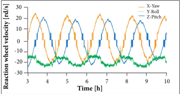
error in Euler angles of a yaw-roll-pitch sequence lasting 7 h (4 orbits, approximately). Although the error exceeds the speciied pointing requirement, it is still inside the allowed range most of the time. he reaction wheel speed is shown in Fig. 8. An angular momentum corresponding to a 200 rpm (≈21 rad/s) was commanded in the magnetic controller for both pitch axis and roll-yaw plane.
rrwm gtr
grw
CTR
CRW
TR
RW
q, ω
ω
rw
Satellite
ratt
+
+
+
– –
–
3 4 5 6 7 8 9 10
-30 -20 -10 0 10 20
Time [h]
Euler angles XYZ [deg]
X: Yaw Y: Roll Z: Pitch
3 4 5 6 7 8 9 10
-30 -20 -10 0 10 20 30
Time [h]
R
eac
ti
o
n w
he
el v
el
o
ci
ty [r
d/s]
X-Yaw Y-Roll Z-Pitch
Figure 6. EPM control with reaction wheels and wheel speed damping with magnetic control.
Figure 7. Simulated attitude error in EPM mode with reaction wheel and magnetic control for wheel momentum unloading.
Figure 8. Simulated reaction wheel speed, with magnetic wheel speed control set on −21 rad/s for pitch and 21 rad/s in roll-yaw plane.
he RW model comprehends a dead band of 50 rpm around the 0 speed, according to supplier data, besides a torque and speed hardware limits. he dead band proved to be signiicant in attitude stabilization and pointing accuracy. A simulation of the EPM was carried out using the Kalman ilter to estimate the attitude and a low pass ilter on the simulated gyroscope. he gyro model considers a drit, or bias, a bias instability, a Gaussian noise, sensitivity scale factor error and crossover coupling sensitivity. A low pass ilter is applied to the simulated gyro measurements prior to Kalman iltering. Magnetometer and CSS models are based on Gaussian noise, scale factor errors and cross-axis coupling only. On Earth shadow the attitude is still estimated using MAG but with reduced accuracy. he proportional magnetic control to unload the RW momentum is composed of 2 individual controllers: to adjust the speed of the pitch wheel, and to control the speed in the roll-yaw plane. So it is possible not only to damp the wheel’s speed, but also to set a non-null angular rate on pitch axis or on the roll-yaw plane.
Simulation results of the EPM mode are shown in Figs. 7 and 8. Figure 7 presents steady state of the attitude pointing
EPM with Magnetic Control
Due to energy saving, the EPM with magnetic control, which will be switched by ground command, is the main attitude controller running on the satellite. It employs a PID controller based on the Conventional Cross Product Law (CCPL) (Camillo and Markley 1980) to obtain the magnetic moment to be applied on the MT. The magnetic moment will be commanded by PWM (Pulse Width Modulation) acting on the coils. Since this control is unable to generate torque around the Earth’s magnetic field, the controller to be applied has to be very weak, just enough to compensate the disturbance torques. So, the slow variation of the Earth’s field with respect to the orbit frame can be used to allow torques in all axes. The derivative gain was chosen relatively large, to stop the satellite attitude motion with respect to the orbital frame. The integral torque, on its turn, has to be very small and acts to compensate the external disturbances. The proportional gain remains in the middle.
to the TRIAD algorithm is available only on the sunlit part of the orbit. During shadow the magnetic three-axis control takes no action, except by the integral control, which remains active with the last value computed before the satellite enters in Earth shadow. Additionally, satellite angular rate was obtained with a low pass filter applied to a numeric derivative of the attitude, resulting in a less noisy control. To avoid unnecessary control action that happens when the control torque vector is almost aligned to the Earth’s magnetic field, a dead band on the control was introduced, which turns off the coils whenever the angle between these vectors is less than 53°. The gains were adjusted to each axis: the higher the moment of inertia the higher the gain. Attitude error was calculated again by the Euler angles (yaw-roll-pitch) with respect to the orbital frame. A maximum duty-cycle of just 10% was adopted in the PWM of the magnetic torque coils, to avoid sudden changes in control action. However, the 0.001 Am2 residual
magnetic dipole on the satellite proved to be strong enough to destabilize the attitude when the MT is the only actuator. That means that a magnetic cleanliness on the satellite during integration shall be necessary in order to reduce the dipole to at least 10% of that value. The simulation results assume that the maximum residual dipole is, therefore, 0.0001 Am2. Figure 9 shows the attitude error in EPM with
3-axis magnetic control, in terms of the Euler angle, from an Euler-axis and angle attitude representation. From an unknown initial attitude, the satellite reaches the steady state after 15 h, approximately. The final error is still large, around 30° maximum, but it is acceptable for this type of control. There are several reasons that explain this large final error, but the inability of the gyroscope to sense such small angular rates, of 10-4 rad/s magnitude, is the major one.
ONBOARD SOFTWARE
The architecture of the ITASAT onboard software was designed following the modularity applied to the CubeSat structure and hardware; in this context, modularity means the capability to isolate sotware modules (minor parts of the sotware) of the remaining system. his modularity is a key point for ITASAT, since one of the major objectives of this project is to develop a multi-mission platform. he modularity allows exchanging parts of the system with small impact in the whole system, thus reducing some eventual rework and helping in the execution of the tests, because once the module is validated, it integrates with the onboard sotware and only the interfaces need to be validated, usually during integration tests. Other advantage of the modular system is the ability to identify independent parts and to develop them in a parallel way, thus allowing an optimized development of the whole system. However, this kind of development imposes new challenges, because each module of the system shall be clearly deined, detailing its features, vulnerabilities and interfaces, which is not easily done. In the case of ITASAT, Uniied Modeling Language (UML) (Object Management Group 2016a) and Systems Modeling Language (SysML) (Object Management Group 2016b) were used to design all the system characteristics: the irst one was used strictly for the sotware and the second one for general purpose of the system.
SOFTWARE COMPONENTS
The ITASAT onboard software was structured in components, modules and units, with the components being sets of modules and the modules as sets of units. he modules inside a component contain speciic features of that component. Generally, the sotware components have many modules with similar features. For instance, in the ITASAT there is a sotware component called Internal Communication; this component has many sotware modules with features related to communication between parts of the system, either the communication among diferent equipment or components of the same sotware on the onboard computer. Figure 10 illustrates the UML modeling of the Internal Communication component. All the sotware components of ITASAT were represented using component diagrams. Two components are shown in Fig. 10: Internal Communication and General Function Management, and also 3 interfaces are shown: getIcData, setIcOpMode, and getEquipmentData.
0 5 10 15 20 25
0 50 100 150 200
Time [h]
Eu
le
r a
ng
le
t
o
re
fe
re
nc
e f
ra
me [d
eg]
Figure 12. ITASAT internal subsystem distribution. Each interface is available in the Internal Communication and
can be used by the General Function Manager. herefore each component can be individually modiied, while keeping the interfaces unchanged, without afecting the functionalities of other components.
<< softComponent>>
Internal Comm. (OBDH)
setIcOpMode getIcData
getEquipmentData
<< softComponent>> General Functions Management
P
ay
lo
ad
s
P
ay
lo
ad
s
A
tt
it
ude co
n
tr
o
l
On
b
o
ar
d C
o
m
p
u
ter
A
tt
it
ude co
n
tr
o
l
P
o
w
er a
n
d en
er
g
y
Figure 10. Example of modeling components using UML.
SOFTWARE EXECUTION
Another characteristic of the software components are the tasks controlled by the real-time operating system FreeRTOS (Real Time Engineers 2016). These tasks control the software operation, and mostly, can be configured independently, which brings modularity not only on design level, but also on execution level. Figure 11 illustrates the software layers for the ITASAT. It shows that lower-level tasks such as hardware configuration and drivers are hidden from the software components by the real-time operating system, which is responsible for managing the execution of those components. Each software component has tasks to control its own operation, and therefore the components can be developed and tested apart each other, by activating or deactivating the tasks of interest.
ASSEMBLY, INTEGRATION AND TESTING
The ITASAT-AIT program aims to establish system integration procedures and to apply standard methods for validation and veriication testing. With these 2 objectives in mind, the program seeks to develop a modular platform that minimizes the physical interaction between components. he modular goal impose restrictions to the satellite resulting a system composed of several self-contained units that can be easily removed or replaced without signiicant changes in the platform. his concept allows cost reduction by 10 to 15% and enables the platform to be employed in diferent tasks with diferent payloads, besides schedule reduction of AIT activities, mission customization, design heritage, and technology development and consolidation (Kingston 2005).
he ITASAT has a structure volume of six CubeSat units, or 6U, organized in a matrix layout of 2 × 3 units. he internal subsystems were arranged in the units according to (Fig. 12):
• 1U for Power and Energy Subsystem. • 1U for Onboard Computer Subsystem.
• 2U for Attitude Determination and Control Subsystem. • 2U for Payloads.
here are several models that can be used for development and veriication process (European Cooperation for Space Standardization ECSS 2012). he philosophy of model deines the
Figure 11. Software layers. Hardware Internal
Communication (CSP)
General Function Management
Payloads Management
Attitude Control
System
determination based on two vectors combined with a filter estimation process, which uses the information provided by the gyros, proved to be adequate to meet the modest pointing requirements, with attitude determination accuracy around 10 degrees. The attitude control is performed by magnetic coils that provides stability during most of the orbit, and reaction wheels which allow high pointing accuracy but for limited time due to availability of onboard power. Simulations of the attitude control of ITASAT were quite realistic, with the inclusion of different effects that contribute to assure realism, based on the characteristics of the sensors and actuators. A Kalman filter that estimates the attitude quaternion with the gyro bias allowed a smooth control action either with the reaction wheels or with the magnetic coils. An important point to emphasize is that the ITASAT shall be the first 3-axis attitude stabilized satellite with reaction wheels whose control logic and software developments, allied to testing and qualification procedures, were totally carried out in Brazil.
AUTHOR’S CONTRIBUTION
Carrara V carried out the attitude simulation and control laws; Carrara V, Makita DH, and Januzi RB conducted the onboard attitude control sotware design and programming; Januzi RB, Sato LS, and Makita DH designed the onboard sotware for data handling; Sato LS and Santos LFP conceived the AIT and satellite layout; Carrara V, Januzi RB, and Santos LFP wrote the main text, with close colaboration of Sato LS. optimal number and characteristics of physical models needed
to achieve conidence in product veriication and a smaller impact on costs and risks. ITASAT design will rely in 2 models: the engineering model for functional testing and staf training, and the proto-light model for acceptance testing and system qualiication. However, according to the CubeSat philosophy, the components used for both models shall be the same, which simpliies the qualiication and acceptance procedures. In fact, the proto-light model is needed just because the components of the satellite have been stressed during qualiication and acceptance tests to validate the platform, and therefore can not be used for light or proto-light models.
he ITASAT AIT campaign foresees random and sinusoidal vibration testing, shock analysis and thermo-vacuum cycles, together with mass properties and magnetic balancing. All these tests are required to increase product quality and to prevent failures that usually can occur in CubeSats. It is estimated that the ITASAT AIT campaign lasts 48 days.
CONCLUSIONS
The ITASAT project is being carried out by university students with funds provided by the Brazilian Space Agency (AEB). The solution adopted for the platform, a 6U CubeSat, can accommodate several payloads with different attitude pointing and stability requirements. Subsystems were pur- chased directly from the industry, while the payloads are being developed, tested and qualified by leading researchers. The solution adopted for the ADCS, with attitude
REFERENCES
Amorim J, Martins Filho LS (2016) Experimental magnetometer calibration for nanosatellites’ navigation system. J Aerosp Technol Manag 8(1):103-112. doi: 10.5028/jatm.v8i1.586
Babcock EP, Bretl T (2011) CubeSat attitude determination via Kalman iltering of magnetometer and solar cell data. Proceedings of the 25th Annual AIAA/USU Conference on Small Satellites; Logan, USA.
Black HD (1964) A passive system for determining the attitude of a satellite. AIAA J 2(7):1350-1351. doi: 10.2514/3.2555
Bushenkov VA, Ovchinnikov MY, Smirnov GV (2002) Attitude stabilization of a satellite by magnetic coils. Acta Astronaut 50(12):721-728. doi: 10.1016/S0094-5765(02)00011-5
Byrnest CI, Isidori A (1991) On the attitude stabilization of rigid spacecraft. Automatica 27(1):87-95. doi: 10.1016/0005-1098(91)90008-P
Camillo PJ, Markley FL (1980) Orbit-averaged behavior of magnetic control laws for momentum unloading. J Guid Control Dynam 3(6):563-568.
Carrara V (2015) An open source satellite attitude and orbit simulator toolbox for Matlab. Proceedings of the 17th International Symposium on Dynamic Problems of Mechanics; Natal, Brazil.
Carrara V (2016) Attitude determination and control of ITASAT CubeSat. Proceedings of the 26th AAS/AIAA Space Flight Mechanics Meeting; Napa, USA.
European Cooperation for Space Standardization (2012) Space Engineering: veriication guidelines; Noordwijk, The Netherlands.
Hoots FR, Roehrich RL (1980) Models for propagation of NORAD Element Sets. Spacetrack Report No. 3. Colorado Springs: Aerospace Defense Center.
International Association of Geomagnetism and Aeronomy (2015) International Geomagnetic Reference Field; [accessed 2017 Jan 19]. http://www.ngdc.noaa.gov/IAGA/vmod/igrf.html
Kelso TS (2015) Celestrack NORAD two-line element sets: current data; [accessed 2017 Jan 27]. http://www.celestrak.com/NORAD/ elements/
Kingston J (2005) Modular architecture and product platform concepts applied to multipurpose small spacecraft. Proceedings of the 19th Annual AIAA/USU Conference on Small Sallite; Logan, USA.
Lefferts EJ, Markley FL, Shuster MD (1982) Kalman iltering for spacecraft attitude estimation. J Guid Contr Dynam 5(5):417-429. doi: 10.2514/3.56190
Li J, Post M, Wright T, Lee R (2013) Design of attitude control systems for CubeSat-class nanosatellite. Journal of Control Science and Engineering 2013(2013):Article ID 657182. doi: 10.1155/2013/657182
Lovera M, Astoli A (2004) Spacecraft attitude control using magnetic actuators. Automatica 40(8):1405-1414. doi: 10.1016/j. automatica.2004.02.022
Markley FL (1998) Attitude determination using two vector measurements. NASA Goddard Space Flight Center, Report. 99-001; [accessed 2017 Jan 27]. https://ntrs.nasa.gov/archive/nasa/casi.ntrs.nasa. gov/19990052720.pdf
Markley FL, Crassidis JL (2014) Fundamentals of spacecraft attitude determination and control. New York: Springer.
Object Management Group (2016a) Systems Modeling Language (UML) resource page; [accessed 2017 Jan 27]. http://www.omg.org/spec/ UML/
Object Management Group (2016b) OMG Systems Modeling Language; [accessed 2017 Jan 27]. http://www.omgsysml.org/
Oluwatosin AM, Hamam Y, Djouani K (2013) Attitude control of a CubeSat in a circular orbit using reaction wheels. Proceedings of the AFRICON, 2013; Pointe-aux-Piments, Mauritius.
Psiaki ML (2001) Magnetic torquer attitude control via asymptotic periodic linear quadratic regulation. J Guid Control Dynam 24(2):386-394. doi: 10.2514/2.4723
Quadrino MK (2014) Testing the attitude determination and control of a CubeSat with hardware-in-the-loop [Master’s thesis]. Cambridge: Massachusetts Institute of Technology.
Real Time Engineers (2016) FreeRTOSTM; [accessed 2017 Jan 19];
http://www.freertos.org/
Shuster MD, Oh SD (1981) Three-axis attitude determination from vector observations. J Guid Control Dynam 4(1):70-77. doi: 10.2514/3.19717
Silani E, Lovera M (2005) Magnetic spacecraft attitude control: a survey and some new results. Contr Eng Pract 13(3):357-371. doi: 10.1016/j. conengprac.2003.12.017
Söken HE, Hajiyev C (2014) Estimation of pico-satellite attitude dynamics and external torques via Unscented Kalman Filter. J Aerosp Technol Manag 6(2):149-157. doi: 10.5028/jatm.v6i2.352
Vega K, Auslander D, Pankow D (2009) Design and modeling of an active attitude control system for CubeSat class satellites. Proceedings of the AIAA Modeling and Simulation Technologies Conference; Chicago, USA.