! " #$ ! % % & '
!
"
" #
#
$
%!
#
& !'
& (
In sheet metal stamping, several variables must be taken into account such as the material’s mechanical properties, the tool’s geometry, interface lubrication between punch and sheet metal and deformation rate, among others. This paper reports on a study of the lubricant’s influence on the stretching forming process. The lubricants used ranged from liquid, such as mineral and vegetable oils with extreme pressure additives and synthetic fluids to solid PVC (polyvinyl chloride) and polyurethane films. In this work, the main objective was to study a minor strain profile as an alternative method to analyze the influence of solid and liquid lubricants on stretching forming of high stampability steels (DC 06). The minor true strain distribution profile was obtained, from the die radius to the punch pole, from stamping tests with stretching characteristics. Analyses of the strain distribution profile and of the fracture position allow an evaluation of the lubrication efficiency. Of the five lubricants studied, the results indicated that the solid polyurethane film yielded the best performance, promoting a more homogeneous distribution profile of the minor true strain (ε2), increasing from the die radius to the punch pole, where tearing of the metal sheet occurred.
Keywords: hemispherical punch-stretching, lubrication and extra deep-drawing steel
Introduction
1
Stamping is a process used in the manufacture of parts from sheet metal. Among the major users of this process are the automotive and home appliance industries, which seek to increase their competitiveness by reducing manufacturing time and cost (Klocke and Maβmann, 2005).
The evaluation of whether or not a sheet metal can be formed without defects depends on the material’s properties, surface conditions, size and shape of the blank, lubrication, press speed, pressure applied by the punch and the die and punch design (Kuzman, 2000) and (Brown and Bosler Jr., 2006).
According to Keeler (2000), when a sample tears or shows excessive thinning, more lubricant is often added in an attempt to solve the problem. However, this is not always the best solution and the lubrication is still little studied and poorly understood (Keeler, 2001).
Lubrication of the punch does not affect deep drawing to any significant extent as if does in stretching deformation mode. For the stretching condition the punch must be well lubricated so that the strains can be prolonged to higher deformation levels (Keeler, 1968). Besides, subtle differences in the stamping process, i.e., die design and metallurgy of the piece, can strongly affect the lubricant performance (Kren, 2003).
In the flange region, in stretching forming, or more precisely, in the draw bead the friction should be as high as possible so that the flow of the sheet into the die is rendered difficult and thus increasing sheet tension. The same holds true for the die radius. However, friction should be as low as possible in the punch radius; there should be a relative movement between the punch surfaces and the sheet metal, which is being formed at the thickness reduction expense. The opposite occurs in deep drawing mode. In this forming situation the material needs to flow into the die cavity. For this reason, in the flange and on the die radius regions, the friction should be as low as possible to enable the material to flow freely. However, the same thing should not occur on the punch radius,
Paper accepted August, 2008. Technical Editor: Anselmo Eduardo Diniz.
where friction should be at its maximum so that no relative movement occurs between the surfaces. This is important to prevent the material from tearing prematurely reaching a high deformation level.
The stamping success, in terms of part integrity and surface quality, is strongly dependent on the tribological behavior during the process. This behavior is a result of a complex set of factors such as tools design, blankholder force, surface quality and topography of both tools and sheet materials, and also of the lubricant properties (Carcel et al., 2004).
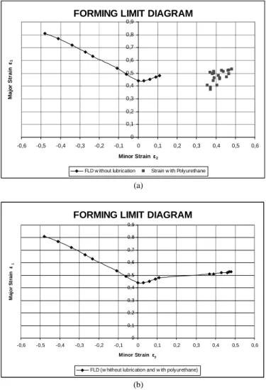
Recently, Tigrinho, (2005) demonstrates the FLC (Forming Limit Curve) for the DC06 steel obtained without lubrication and the extension of the minor true strain curve for 200x200mm specimen obtained with the application of polyurethane as lubricant, Figs. 1a and b. Using this lubricant, points with a higher minor true strain (ε2) were generated, with values of about 0.48, while the true
strain level reached only 0.11 without lubrication. These results indicate a real gain of 37% in the material’s forming ability in stretching forming (using polyurethane).
In this work, a minor true strain profile was proposed as an alternative method to analyze the influence of solid and liquid lubricants on stretching forming of DC 06 high stampability steel.
Experimental Procedure
The material used was a cold-rolled mild steel (0.7mm thickness) produced by Thyssen Krupp to the DC06 specification (EN 10152, 1993). This material was selected for the laboratory tests, because it is a high stampability material, i.e. hardening coefficient (n) of 0.26 and anisotropy coefficient (r) of 2.26. The material showed ε1=0.81 and ε2=-0.48 on deep drawing state,
ε1=0.44 and ε2=0 on plane strain state and ε1=0.53 and ε2=0.48 on
FORMING LIMIT DIAGRAM
0 0,1 0,2 0,3 0,4 0,5 0,6 0,7 0,8 0,9
-0,6 -0,5 -0,4 -0,3 -0,2 -0,1 0 0,1 0,2 0,3 0,4 0,5 0,6
Minor Strain ε2
M
a
jo
r
S
tr
a
in
ε1
FLD w ithout lubrication Strain w ith Polyurethane
(a)
FORMING LIMIT DIAGRAM
0 0,1 0,2 0,3 0,4 0,5 0,6 0,7 0,8 0,9
-0,6 -0,5 -0,4 -0,3 -0,2 -0,1 0 0,1 0,2 0,3 0,4 0,5 0,6
Minor Strain ε2
M
a
jo
r
S
tr
a
in
ε1
FLD (w hithout lubrication and w ith polyurethane)
(b)
Figure 1. The DC06 steel forming limit diagram – (a) comparison of the forming limit curve obtained without punch lubrication and the points of maximum attained strain (ε2) using polyurethane lubricant and (b) final
forming limit curve without lubrication and the 200x200mm test specimen with polyurethane.
A total of five liquid and solid lubricants were used, classified as water-emulsive, synthetic oils and solid films (Brown 2006, Klann 2000 and Trivett et al. 2004):
• Polyurethane → solid lubricant, 0.50mm layer thickness;
• PVC (polyvinyl chloride) film → solid lubricant, 0.05mm layer thickness;
• Mineral oil + vegetable oil → emulsive (1:2), with extreme pressure (EP) additives, viscosity at 40°C of 30cSt and density at 20°C of 0.880g/cm3;
• Synthetic fluid → prelube (used as anticorrosive after rolling), biodegradable, easy removal, viscosity at 40°C of 35cSt and density at 20°C of 0.880g/cm3;
• Synthetic fluid → emulsive (1:2), easy removal, viscosity at 40°C of 17cSt and density at 20°C of 0.880g/cm3.
After application of the polyurethane on the sheet metal surface, a 3-hour wait for curing should be observed while the resin mixes with its catalyzer.
The forming limit test (at fracture) was carried out using a 50mm radius hemispherical punch and a 10mm radius die (106mm internal diameter). Originally, this test includes a total of 18 test specimens, all of them 200mm long, but with widths varying from 40mm to 200mm (Nakazima et al., 1968). This variation in the width of the test specimens is the determining factor for providing
data from the stretching forming – when the sample’s width suffices for the full action of the draw bead around the entire stamped cup – to plane state deformation, and to negative minor strain – when the sheet is narrower, so that a lateral portion of the test specimens is not held down by the draw bead. In this study, the tests were carried out only with 200x200mm test specimens, which were used with and without lubrication, to simulate mainly the stretching condition, since lubrication has no significant influence on deep drawing as in stretching mode (Keeler, 1968).
In order to measure the minor true strain (ε2) a 4.2mm diameter
circular grid was printed on the test specimen’s surface. The grid was printed using a process developed in the Forming Laboratory (LABCONF) of the Federal University of Paraná (Tigrinho, 2004). This process differs from the processes used previously (electrolytic marking, photo-sensitive resin or laser). This marking process uses a screen (mask), similar to the screens used in silkscreen process, and a grid fixer developed for the coated metallic sheet employed. This process proved to be simpler, easier to apply and cheaper. It requires no special equipment for the grid printing process.
In the stamping process the test specimens, with the uniformly printed circular grid, were deformed up to the moment of rupture. The major and minor strains can be determined with precision, leading to identification of each deformation zone, and eventually to methods for preventing stamping defects (Xu, 2007). After the tests, measurements were taken of the ε2 deformation axes of the circles
positioned along a straight line, from the border of the stamped body (die radius support site) up to the center of the body (punch pole action site), Fig. 2. The measurements were taken on the side of the test specimen opposite to the fracture in order to avoid measurements in cracked circles (Moreira et al., 2003). An average of three test specimens was evaluated for each test and the results were recorded as a mean value (three measurements).
Figure 2. Test specimen illustrating the position of measured points, from the die radius to the punch pole.
The results were compiled on a graph that shows the variation of the minor true strain, from point 1, corresponding to the die radius, to point 12, corresponding to the punch pole. As we analyzed a simple shape part the forming limit strain diagram was chosen instead the forming limit stress diagram – independently on strain path (Gronostajski et al., 2004).
Results and Discussion
consistently occurred between the die radius and the punch pole. The location of the fracture can determine homogeneous deformation or if deformation peaks were generated. This can indicate whether the lubrication system was efficient or inefficient.
Figure 3 shows the minor true strain distribution profile of the 200x200mm test specimen tested with and without lubrication.
Deformations distribution profile Without lubrication mean value 0 0,05 0,1 0,15 0,2 0,25 0,3 0,35
1 2 3 4 5 6 7 8 9 10 11 12
Dis tance of die radius to the punch pole
M a jo r s tr a in ε2 Without lubrication (a)
Deformations distribution profile
Oil EP mean value 0 0,05 0,1 0,15 0,2 0,25 0,3 0,35
1 2 3 4 5 6 7 8 9 10 11 12
Distance of die radius to the punch pole
M a jo r s tr a in ε 2 Oil EP (b)
Deformations distribution profile
Emulsive synthetic fluid
mean value 0 0,05 0,1 0,15 0,2 0,25 0,3 0,35
1 2 3 4 5 6 7 8 9 10 11 12
Distance of die radius to the punch pole
M a jo r s tr a in ε 2
Emulsive synthetic fluid
(c)
Deformations distribution profile
Prelube synthetic fluid
mean value -0,05 0 0,05 0,1 0,15 0,2 0,25 0,3 0,35
1 2 3 4 5 6 7 8 9 10 11 12
Distance of die radius to the punch pole
M a jo r s tr a in ε 2
Prelube synthetic fluid
(d)
Deformations distribution profile
PVC film mean value -0,05 0 0,05 0,1 0,15 0,2 0,25 0,3 0,35
1 2 3 4 5 6 7 8 9 10 11 12
Distance of die radius to the punch pole
M a jo r s tr a in ε 2 PVC film (e)
Deformations distribution profile
Polyurethane film mean value 0 0,05 0,1 0,15 0,2 0,25 0,3 0,35 0,4 0,45 0,5 0,55
1 2 3 4 5 6 7 8 9 10 11 12
Distance of die radius to the punch pole
M a jo r s tr a in ε 2 Polyurethane film (f)
The curve shown in Fig. 3a, without lubrication, shows a minor true strain peak (ε2) of 0.32 at point 5 i.e., both the rupture and the
strain peak occurred away from the pole, characterizing a heterogeneous deformation. The rupture occurs along the pole, with a minor true strain peaks formation, when inadequate lubrication is used in the stretching condition.
The deformation distribution profiles depicted in Figs. 3b, c, d and e, correspond to the stamped samples with a combination of mineral and vegetable oils with EP additives, emulsive synthetic fluid, prelube synthetic fluid, and solid PVC film, respectively. These figures consistently show a maximum minor true strain peak (ε2) at point 5, similar to that produced without lubrication (Fig. 3a).
For all cases both the rupture and the minor true strain peak occurred away from the punch pole. This is characteristic of inexistent lubrication condition and an inadequate condition for the stretching forming mode. This mode requires good lubrication and the smallest possible friction at the punch/sheet metal interface allowing for a more homogeneous deformation profile.
With mineral and vegetable oil with EP and emulsive synthetic fluid, Figs. 3b and c, respectively, it could be noted that although the minor true strain peaks are concentrated at point 5, they were less marked than those produced with prelube synthetic fluid and PCV film, Figs. 3d and e, respectively. These cases displayed a much more marked deformation profile at their minor true strain point (ε2)
indicating that, even though their minor true strain peaks occurred at the same point, the mineral and vegetable EP oil and emulsive synthetic fluid were more effective than the prelube synthetic fluid and the PVC film in stretching condition.
The curve showed in Fig. 3f, obtained with the use of polyurethane film, shows the minor true strain (ε2) increasing from
0.03 at the die radius to a maximum of 0.48 at the punch pole. This characterizes a more homogeneous condition without minor true strain peaks away from the punch pole, indicating that the lubrication was efficient i.e. contributing to a more uniform deformation profile.
This more homogeneous deformation profile will result in stretched formed products with lower residual stresses and, therefore, tending to make better use of the material formability.
Studies had demonstrated the effect of the lubricant on the materials conformability (Jeffery, 2003). In deep drawing process of aluminum sheet the solid lubricant promoted an increase of 40 to 50% in the materials conformability compared with the performance of the liquid lubricants. Another good performance was in the forming of a steel plate of high resistance, which solid lubricant allowed the material stretching from 26 to 32% compared with the liquid lubricants.
Experimental tests in the stamping of 5000 back covers of the Dodge Dakota using solid lubricant reduced the amount of parts with defects for less than 1%. The same part showed 40% of defective peaces using oil based lubricant, (Jeffery, 2003).
It could be also noted that with good lubrication the minor true strain (ε2=0.48) approaches of the major true strain (ε1=0.53)
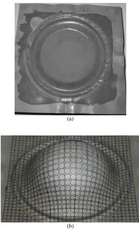
characterizing a pure biaxial stress state. An important fact to be considered is that the polyurethane film remained continuous, without tearing, even after stamping (Fig. 4a and b).
With good lubrication in the stretching forming tearing tends to occur close to the pole with high values for the minor true strain (ε2), very often close to the major true strain (ε1) (Hosford, 1993).
The homogeneous minor true strain profile attained, with DC06 steel sheet, using the polyurethane film is due to the film efficiency that separates the sheet metal surface from the punch surface, preventing them from coming into contact, thus reducing friction and providing a more homogeneous deformation. In this case, it is unnecessary to shear the surface between the sheet and the punch. As the sheet metal is deformed by the punch, the polyurethane
deforms, allowing relative movement between the surfaces without the need for shearing, rendering a more homogeneous deformation. With the polyurethane film the rupture occurred very close to the punch pole.
(a)
(b)
Figure 4. Formed sample: (a) continuous polyurethane film even after forming (devoid of tearing) and (b) top view of the failed sample.
Conclusion
During forming processes, lubricants typically applied along the tool-workpiece interface increases sheet formability. These lubricants allow contact pressures to be more evenly distributed and improve the surface quality of the formed parts. When the solid polyurethane film was used, the minor true strain distribution profile (ε2) was more homogeneous, starting from a low deformation level
References
Brown, M. and Bosler, Jr.P., February 2006, “Selecting Stamping Lubricants for Advanced High-Strength Steels”, Magazine Metal Forming, pp. 28-31.
Carcel, A.C., Palomares, D., Rodilla, E. and Perez Puig, M.A., October 2004, “Evaluation of vegetable oils as pre-lube oils for stamping”, Materials and Design, 26, pp. 587-593.
EN 10152, 1993, “Produtos Planos de Aço Eletricamente Zincados e laminados a Frio” (In Portuguese), Deutsche Industrie Normen.
Gronostajski, J., Matuszak, A., Niechajowicz, A. and Zimniak, Z., 2004, “The System for Sheet Metal Forming Design of Complex Parts”, Journal of Materials Processing Technology 157-158, pp. 502-507.
Hosford, W. F. and Caddell, R. M., 1993, “Metal Forming – Mechanics and Metallurgy”, 2nd ed. N. J.: Prentice Hall.
Jeffery, B., June 2003, “Stretching Metal´s Forming Limits with HSP Lubricants”. Magazine The Fabricator.
Klocke, F., Maβmann, T., Gerschwiler, R., 2005, “Combination of PVD tool coatings and biodegradable lubricants in metal forming and machining”, Wear – 259, pp. 1197-1206.
Keeler, S. P., April 2000, “To Lube or Not to Lube”, Magazine Metal Forming, pp. 68-69.
Keeler, S.P., August 2001, “The Barrier Lubricants Are Coming”, Magazine Metal Forming, pp. 72-73.
Keeler, S. P., 1968, “Understanding Sheet Metal Formability”, Machinery. Kim, H., Sung, J.H., Sivakumar, R., Altan, T., November 2007, “Evaluation of stamping lubricants using the deep drawing test”, International Journal of Machine Tools & Manufacture, Volume 47, Issue 14, pp. 2120-2132.
Klann, R., December 2000, “Lubricants for high-Speed Stamping”, Magazine Metal Forming, pp. 30-33.
Kren, L.A., January 2003, “The Pursuit of Proper Lube Strategies”, Magazine Metal Forming, pp. 28-31.
Kumar, D.R., 2002, “Formability analysis of extra-deep drawing steel”, Journal of Materials Processing Technology 130-131, pp. 31-41.
Kuzman, K., 2000, “Environmentally Friendly Lubricants in Deep Drawing of Steel Sheet Metal”, Enform Project, Slovenia, TECOS Celje.
Moreira, L.P., Sampaio, A.P., Ferron, G. and Lacerda, A.C., 2003, “Análise numérica e experimentação da influência da espessura inicial das deformações limites em chapas”, (In Portuguese), Conferência Nacional de Conformação de Chapas, 6, 2003, Porto Alegre. Anais Porto Alegre: UFRGS – Centro de Tecnologia, pp. 39-49.
Nakazima, K., Kikuma, T. and Hasuka, K., 1968, “Study on Formability of Steel Sheets”, Yawata Tech. Rep., pp. 141.
Tigrinho, L.M.V., 2004, “Avaliação das Deformações de Chapas Finas e Curvas CLC para Diferentes Geometrias de Punções”, (In Portuguese), MSc. Thesis, Mechanical Engineering – Technology Sector, Universidade Federal do Paraná, Curitiba, Brazil, 127p.
Tigrinho, L.M.V., 2005, “Influência da Lubrificação na Estampagem Via Análise das Deformações Obtidas em uma Chapa de Aço de Alta Estampabilidade” (In Portuguese), MSc. Thesis, Mechanical Engineering – Technology Sector, Universidade Federal do Paraná, Curitiba, Brazil, 112 p.
Trivett, B., Elenteny, D. and Manfreda, J., April 2004, “Next Generation Synthetic Forming Fluids”, Magazine the Fabricator.