Applying an Enhanced Path Finding Avatar for a
Virtual Environment
Jui-Fa Chen, Wei-Chuan Lin*, Li-Hao Yang
Department of Computer Science and Information Engineering,
TamKang University, Danshui, Taiwan 25137, R.O.C
E-mail: [email protected]
*Department of Information Technology, Tak-Ming College,
*E-mail: [email protected]
Abstract—There are several types of landform and objects in the virtual environment such as obstacles, move objects and items … etc. A path finding avatar should evaluate the whole environment properly, and design the policies or plans to find the path to the specific goal. With the goal of “moving to specific location”, this paper focuses on building the behavior model of a path finding avatar in a virtual environment. This paper proposes a hybrid method which combined the Potential Field Methods (PFM) and Virtual Force Field Methods (VFF) for a path planning avatar to evaluate the virtual environment. From the experimental results, the behavior avatar with the proposed method can move to the specific goal better than pure using the mechanism of PFM or VFF. In the future, the behavior models of original users could be kept in the behavior data-base for analyzing or training by this proposed method. In this way, this proposed method could apply the Bayesian Network mechanism for more advanced personalization.
Index Terms—virtual environment, intelligent behavior avatar, potential field, virtual force field, path planning
I. INTRODUCTION
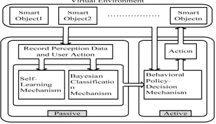
There are many smart objects (SO) and different kinds of mobile agents in a virtual environment. Different mobile agent possesses different characteristics and can communicate with other mobile agents and SOs according to user’s action. However, these mobile agents have no intelligence to take actions when the user is not existed in the virtual environment. Therefore, the intelligence mechanism should be added to the mobile agent to enhance its communication ability to record or complete the user’s action. This paper proposes an Intelligent Behavior Avatars (IBAs) to provide this intelligent mechanism. There are also many IBAs in a virtual environment [1, 2], most of them have their tasks to accomplish, and the IBAs should have their specified role to play. Through the communication among SOs, IBA can analyze the user’s action and learn the user’s behavior to exist in the virtual environment. The proposed virtual environment is to provide a simulated platform and let the reasoning and self-learning mechanisms of IBA to interact with other IBAs. This proposed virtual environment is shown as Fig. 1.1. In Fig. 1.1, every IBA should play two kinds of roles such as passive and active duration behaviors. When the IBA is in the passive duration behavior, the major work is to observe and record the information such as environment status, and user’s action. Through the recorded information, the IBA can utilize the Bayesian classification mechanism to analyze the user’s behavior and characteristics. In this way, the passive duration behavior of IBA can learn the user’s behavior by
a self-learning mechanism. When the user leaves the virtual environment, the IBA replaces the original user and is in the active duration behavior. The IBA can utilize the learning experience that was collected in the passive duration behavior and behaved like the original user in the virtual environment.
Fig 1.1 The roles of IBA play in the virtual environment
Since different goals have different features and characteristics, the IBA should design different mechanisms for solving different goal. The IBA should evaluate the whole virtual environment properly, and design policies or plans for the right path no matter how many obstacles and moving objects the path finding IBA should face. The path finding IBA should avoid hitting the obstacles and moving objects. This paper only focuses on the goal of “moving to specific location”. A path finding IBA should evaluate the situations of the environment and try to go to the specific location. This paper proposes a hybrid method of Potential Field Methods (PFM) and Virtual Force Field Methods (VFF) for evaluating the environment and path planning. By this method, a path finding IBA can evaluate the environment according to the personal characteristics. With the adjustment in the parameters, the path finding IBA can behave just like the original user does. The behavior model of a user based on this proposed method can also be analyzed.
The rest of this paper is organized as follows: Section 2 is the related methodologies. Section 3 describes the proposed system architecture. Section 4 shows the experimental results. Section 5 is the conclusion and future work.
II. RELATED METHODOLOGIES
A. Potential Field Methods
Potential Field Methods (PFM) [3, 4] are broadly used in obstacle
avoidance applications for robots and manipulators [5, 6, 7, 8]. The concept involves that physical features are represented by regions of attraction and repulsion in a virtual field. Different objects generate different potential to the field q. The potential formula is listed as Eq. 2.1:
U(q) = Uatt(q) + Urep(q) ……. (Eq. 2.1)
Where
Uatt(q): attractive potential associated with Goal Urep(q): repulsive potential associated with Obstacles
Obstacles generate repulsive potential and the formula is listed as Eq. 2.2:
⎪⎭ ⎪ ⎬ ⎫
⎪⎩ ⎪ ⎨ ⎧
> ≤ −
=
0 0 2
0
, 0
, ) 1 1 ( 2 1 ) (
ρ ρ
ρ ρ ρ
ρ η
if if x
Urep
……. (Eq. 2.2)
Where the parameters are explained as followed:
η: Constant.
ρ: The shortest distance to the obstacle.
ρ0 : The limit distance of the obstacle influence.
The goal generates attractive potential and the formula is listed as Eq. 2.3:
……. (Eq. 2.3)
Where the parameters are explained as followed:
ξ: Constant.
x: : The position vector of the robot.
xd : The position vector of the goal.
After calculating the potential field for the whole environment, the robot can make their moves according to the potential value of places that are around it [9, 10, 11]. Environment can be evaluated by the potential value as shown in Fig. 2.1. The black zone in Fig. 2.1 is the obstacle, the gray region represents the general potential value; and the darker color represents the higher potential. The robot should try to move from the places with high potential value to the places with low potential value.
Fig. 2.1 The potential field around the T-shape obstacle
Through computing the interactive force in PFM, the potential value is obtained. This potential field value is provided for the robot to evaluate the environment and setup the plan for decision making. As shown in Fig. 2.2,
the soccer robot can make plans to cover teammate or shoot the ball according to the positions of teammate and enemy. The soccer robot can also use the potential field value to design the better shooting path or angle.
Fig. 2.2 The better way for soccer robot to shoot [11]
B. Virtual Force Field Methods
Virtual Force Field method (VFF) is another type of PFM [12, 13]. The VFF method uses the forces generated by objects as a guide to design the path. Just like PFM, objects generate forces according to their effects on the robot. The VFF method uses a 2D Cartesian grid, called the histogram grid, for obstacle representation. The only obstacles in the grid have effects and could generate forces to the robot. As the robot moves, a window is accompanied with the grid and overlaid by a square region. The window is always at the center of the robot’s position. An example of the VFF method is shown as Fig. 2.3.
Fig. 2.3 The robot moves with the VFF method
III. SYSTEM ARCHITECTURE
With the goal of “moving to specified location”, a path finding avatar should evaluate the whole environment properly and decide the policies according to the changing environment. There are many objects in the virtual environment, and different objects have different effects on a path finding avatar. Therefore, a path finding avatar should have different consideration of them.
A. Behavior Procedure of a Path Finding Avatar
The behavior procedure of a path finding avatar can be described as Fig 3.1.
2
|
|
2
1
)
(
datt
x
x
x
U
=
ξ
−
Fig. 3.1 Behavior Procedure of a Path finding Avatar
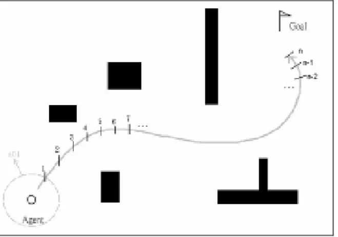
The first step is to observe the whole environment and analyze the received data. A path finding avatar should always keep the latest information of the whole environment to analyze the information and make decision. After receiving data from the whole environment, a path finding avatar should decide which goal to achieve in Step 2. There might be several goals to accomplish at the same time, and a path finding avatar just selects one goal to achieve. In Step 3, a path finding avatar split the selected goal into some sub-goals. The path finding avatar should evaluate the environment and decide how to achieve the goal. However, it is not always easy to tell how much percentage of a goal is accomplished. Therefore, specified decomposition of the specified goal should be designed. The goal achievement rate should be evaluated according to how many sub-goals are done. As shown in Fig. 3.2, a path finding avatar decides a path from left to a goal on the right. The path finding avatar takes the path from the start to the goal, and splits it into n sub-paths as sub-goals. When the ith sub-goals are done, it can conclude that the goal achievement is i/n. A path finding avatar makes his decision to define the goal and sub-goals in Step 4. After that, the path finding avatar makes their moves in Step 5. In Step 6, a path finding avatar checks whether the goal is completed or not. If the goal is not achieved or the environment is changed, this procedure is back to Step 1. With the PFM mechanism, the IBA can compute the potential field value of every object in the environment. The computed potential field value can be used to decide where to move on the next step. The IBA with the PFM mechanism can have good performance in a simple environment. As shown in Fig. 3.3, when the specific goal is surrounding by some obstacles and enemies, the PFM mechanism can have good result on path planning to the goal.
Fig. 3.2 Decomposition of the goal
Fig. 3.3 The path planning by PFM in a simple environment
B. Path Planning with Potential Field Methods
The PFM is first used as the mechanism of path planning. The PFM not only does path planning but evaluates the whole environment. The PFM also allows personalizing evaluation for different environment. Because different characteristic avatars could behave different results of evaluation, they should have different results of path planning.
B.1 Evaluation in PFM
Traditional evaluation of PFM only concerns about the potential produced by obstacles and goal. However, in the proposed environment, other objects such as avatars could have effects on a path finding avatar. Allied and enemy avatars also have different effects. Therefore, they should be considered as two different potentials. Therefore, the total potential
U
(
q
)
of place q is computed by the formula as Eq. 3.1:∑
∑
∑
= + + + = + + + = + + + + + + + + + v i E u i A t i O G q U n q U m q U q U i i i i i 1 1 1 ) ( ) ( ) ( ) ( = U(q) δ γ β α δ δ γ β α γ δ γ β α β δ γ β α α… (Eq. 3.1)
Where the parameters are explained as followed:
UG(q) : The potential produced by Goal UO(q) : The potential produced by obstacles t : The amount of obstacles
UA(q) : The potential produced by allies u : The amount of allies
UE(q) : The potential produced by enemies v : The amount of enemies
α、 、 、δ : Constant.
The PFM could personalize the evaluation of a path finding avatar by adjusting parameters 、 、 、 , so that different path finding avatars with different characteristics should have different evaluations results. After the formula is calculated, each place in the environment has its potential value, so a path finding avatar could evaluate the environment by analyzing the potential value and making decision.
B.2 Problems with PFM
PFM works fine in most of the common environments. However, in a complicated environment, unreasonable paths are planned. As shown in Fig. 3.4, some unnecessary paths are planned. It is called the oscillation phenomenon. When there are too many “corners” or complex obstacles in the environment, serious oscillation phenomenon may cause the path planning to fail. The path would fall into endless loops and never reaches the position of goal.
Fig. 3.4 Unreasonable oscillation appearance in PFM
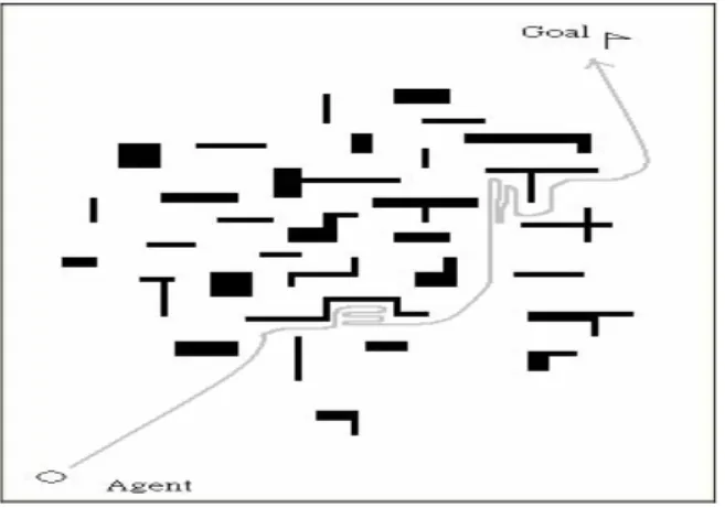
As shown in the left of Fig. 3.5, there are many unnecessary paths around the corners planned by the PFM mechanism. Some of the paths should be removed to speed up the path planning process. When the goal position is almost closed as shown in the right of Fig. 3.5, the IBA with PFM mechanism has planned many unnecessary paths and failed to reach the goal.
Fig. 3.5 The serious oscillation effect by PFM
C. Path Planning with Virtual Force Field Methods
Since PFM performed unreasonable results in a complicated environment with many obstacles, the VFF is used to solve this problem. The VFF is another form of PFM and they are all based on the same concepts of calculation the influences produced by objects.
C.1 Evaluation in VFF
The difference between PFM and VFF is that VFF uses “the sum of forces” to determine which direction to go. The VFF takes forces produced by objects instead of the potential field value which is produced by PFM. Only the forces produced by Goal and those objects in the grid are taken into account for calculating. The VFF solved the oscillation problems in PFM, and produced more smooth paths than PFM.. PFM is to compute all the potential field values produced the forces and make decision. However, VFF is directly used the group
force direction as the direction for the IBA to move.
The VFF mechanism is used to solve the oscillation problem in PFM mechanism. As shown in Fig. 3.6(a), the PFM mechanism has planned many unnecessary paths around the entrance. However, in Fig. 3.6(b), the VFF mechanism can solve this problem and the planning paths are not redundant
Fig. 3.6(a) The path planning results by PFM
Fig. 3.6(b) The path planning results by VFF
C.2 Problems with VFF
As mentioned before, the VFF takes “the sum of forces” into consideration and that is also the problems. When the sum of all forces equals to zero, the avatar would just keep still and do nothing. As shown in Fig. 3.7, Fatt is the attractive force produced by goal and Frep is the repulsive force produced by the obstacle. When the sum of Fatt and Frep equals to zero, the avatar would have no force direction as the direction guide.
Fig. 3.7 Countervailing problems in VFF
The discussions of the attractive and repulsive force are shown as
followed:
z |Fatt| = |Frep|
When the attractive and repulsive forces are the same, the sum of force is equal to zero. In this case, no force direction as the guide, the IBA has no direction guide to move and remains still as shown in Fig. 3.7.
z |Fatt| > |Frep|
When the attractive force is greater than the repulsive force, the sum of force is the subtracting remainder of attractive force. In this case, a force direction is driving IBA toward the goal to move. If the IBA moves and faces the obstacles, the IBA may also remain still as shown in Fig. 3.8(a).
z |Fatt| < |Frep|
When the attractive force is smaller than the repulsive force, the sum of force is the subtracting remainder of repulsive force. In this case, a force direction is driving IBA far away from the goal to move. This would cause the IBA moves and impossible to reach the goal as shown in Fig. 3.8(b).
Fig. 3.8(a) The IBA remains still by VFF.
Fig. 3.8(b) The IBA is impossible to reach the goal by VFF
D. The Hybrid Method of PFM and VFF
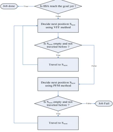
Because there are different problems in PFM and VFF, the proposed method is a hybrid method by combining them to solve the problems. The flowchart of the proposed hybrid method is shown as Fig. 3.9. As described above, the VFF is used as the proposed primary method for path planning. When the path planned by the VFF is failed, the PFM is used as a back-up method. That means that the hybrid method is the
PFM helps the VFF to “get out of the stock” when the path planning mechanism is stocked or bumped into other objects.
Fig. 3.9 The flowchart of hybrid of PFM and VFF mechanisms
Beside the move oscillation, the PFM mechanism is unstable when the path to the goal is very narrow. When the path to the goal is narrow or the entrance is small, the PFM mechanism may not reach the goal and have the oscillation problem. This is because the PFM mechanism is to compute the sum of potential field the produced by the environment. When the environment is surrounding obstacles, the sum potential field value is large because the potential field value of obstacle is set to large value. As shown in Fig. 3.10, when the goal is surrounding by large obstacle, due to the sum of the potential field value produced by obstacles is large, the IBA may not reach the goal.
Fig. 3.10 The potential field problem of PFM
IV. EXPERIMENTAL RESULTS
A. Hardware and Software Environment
The proposed method is implemented in the hardware and software environment as shown in Table 4.1.
Table.4.1 The hardware and software environment CPU Intel® Pentium® M Processor 1.4GHz
RAM DDR333 RAM 1GB
Toolkit J2SDK v1.4
A. Simulation Comparison
In the simulation, solely used the PFM and VFF are compared with the proposed hybrid method in the same environment.
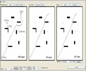
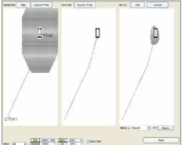
Fig. 4.1 The simulation program result
As shown in Fig.4.1, there are three blocks display the results of path planning. The left one shows the result of PFM, the center one shows the result of VFF, and the right one shows the result of the proposed method. The environment settings are all the same. The following figures are shown in the same way, and the differences among these methods are listed as followed.
B. Simulation and discussion
In the environment with corners as shown in Fig. 4.2, PFM have unreasonable oscillation results as compared with the VFF and the hybrid methods. In Fig.4.3, the environment just has one vertical obstacle. From the simulation result, it shows that the countervailing problems only occur in VFF.
Fig. 4.2 Simple environment with corners
Fig. 4.3 The one vertical obstacle case
If there are many obstacles in the environment as shown in Fig.4.4, both PFM and VFF have problems in such environment as compared with the proposed hybrid method. If the goal is almost sealed by obstacles as shown in Fig.4.5, PFM is got into a serious oscillation loop, and VFF is also failed to reach the goal. However, the proposed method could reach the goal in both cases of Fig.4.4 and Fig.4.5.
Fig. 4.4 The many obstacles environment
Fig. 4.5 The environment with goal is almost sealed
V. CONCLUSIONS and FUTURE WORKS The proposed hybrid method can solves problems in solely used the PFM and VFF. The proposed method is based on the concept of evaluation in potential field to plan the path. In this way, a path finding avatar for path-planning could be simple to implement.
In the future, the original users’ behavior models which utilize the proposed hybrid methods could be analyzed. This means that applying the proposed method to the Bayesian Network mechanism for advanced personalizing of original users should be investigated.
References
[1] Jui-Fa Chen, Wei-Chuan Lin, “Building an intelligent Behavior Avatar in a Virtual World”, The 14th International Conference on Artificial Reality and
Tel-existence (ICAT 2004), 2004, Nov. 30-Dec. 2, pp. 364- 368 [2] Jui-Fa Chen, Wei-Chuan Lin, “Constructing an Intelligent Behavior Avatar in a
Virtual World: A Self-Learning Model Based on Reinforcement”, 2005 International Conference on Information Reuse and Integration (IRI 2005), 2005, August 15-17, pp. 421 – 426
[3] J.R. Andrews, N. Hogan, “Impedance Control as a Framework for Implementing Obstacle Avoidance in a Manipulator” Control of Manufacturing Processes and Robotic Systems, Eds. Hardt, D. E. and Book, W., ASME, Boston, 1983, pp.243-151
[4] O. Khatib, “Real-Time Obstacle Avoidance for Manipulators and Mobile Robots”, International Journal of Robotics Research, vol.5, pp. 90-98, 1986
[5] Frank E. Schneider, Dennis Wildermuth, “A Potential Field Based Approach to Multi Robot Formation Navigation”, IEEE International Conference on Robotics, Intelligent Systems and Signal Processing, October, 2003, pp.680-684
[6] M.G. Park, M.C. Lee, “Experimental Evaluation of Robot Path Planning by Artificial Potential Field Approach with Simulated Annealing”, Society of Instrument and Control Engineers of Japan, August 5-7, 2002, pp.2190-2195
[7] A. Poty, P. Melchjor, A. Oustaloup, “Dynamic Path Planning for Mobile Robots using Fractional Potential Field”, First International Symposium on Control, Communications and Signal Processing, 2004, pp.557-561
[8] Prahlad Vadakkepat, Kay Chen Tan, Wang Ming-Liang, “Evolutionary Artificial Potential Fields and Their Application in Real Time Robot Path Planning” Congress of Evolutionary Computation, San Diego, California, July, 2000, pp.256-263
[9] Prahlad Vadakkepat, Kay Chen Tan, Wang Ming-Liang, “Evolutionary Artificial Potential Fields and Their Application in Real Time Robot Path Planning”, Congress of Evolutionary Computation, San Diego, California, July, 2000, pp.256-263 [10] Takashi Katoh, Kensaku Hoshi, Norio Shiratori, “On Agents’ Cooperative Behavior
Based on Potential Field”, International Conference on Advanced Information Networking and Application, vol.2, no.2, 2004, pp.149-154
[11] A. Tews, G. Wyeth “Multi-Robot Coordination in the Robot Soccer Environment”, Australian Conference on Robotics and Automation, March 30 - April 1, 1999, Brisbane, pp. 90-95
[12] J. Borenstein, Y. Koren, “Real-Time Obstacle Avoidance for Fast Mobile Robots” IEEE Transactions on Systems, Man, and Cybernetics, vol.19, no.5, September/October, 1989, pp.1179-1187 [13] J. Borenstein, Y.Koren, “Real-time Obstacle Avoidance for Fast
Mobile Robots in Cluttered Environments” IEEE International
Conference Robotics and Automation, 1990, pp.572-577
![Fig. 2.2 The better way for soccer robot to shoot [11]](https://thumb-eu.123doks.com/thumbv2/123dok_br/18279414.345431/2.892.466.779.651.872/fig-better-way-soccer-robot-shoot.webp)