An accelerated incremental algorithm to trace the nonlinear
equilibrium path of structures
Abstract
This paper deals with the convergence acceleration of iter-ative nonlinear methods. An effective iteriter-ative algorithm, named the three–point method, is applied to nonlinear anal-ysis of structures. In terms of computational cost, each it-eration of the three–point method requires three evaluations of the function. In this study the effective functions have been proposed to accelerate the convergence process. The proposed method has a convergence order of eight, and it is important to note that its implementation does not re-quire the computation of higher order derivatives compared to most other methods of the same order. To trace the equi-librium path beyond the limit point, a normal flow algorithm is implemented into a computer program. The three–point method is applied as an inner step in the normal flow algo-rithm. The procedure can be used for structures with com-plex behavior, including: unloading, snap–through, elastic post–buckling and inelastic post–buckling analyses. Several numerical examples are given to illustrate the efficiency and performance of the new method. Results show that the new method is comparable with the well–known existing methods and gives better results in convergence speed.
Keywords
Nonlinear analysis, Convergence acceleration, Normal flow algorithm, Three–point method
Hamed Saffaria,∗
, Nadia M. Mirzaib and Iman Mansouric
a Professor and corresponding author, Dept. of Civil Engineering, Shahid Bahonar University of Kerman, P.O. Box 76169-133, Kerman, Iran, Tel: +989131411509
bGraduate Student, Dept. of Civil Engineer-ing, Shiraz University, P.O. Box 71345-3341, Shiraz, Iran.
c
Ph.D. Candidate, Dept. of Civil Engineering, Shahid Bahonar University of Kerman, Ker-man, Iran.
Received 13 Apr 2012; In revised form 11 May 2012
∗Author email: hsaffari@mail.uk.ac.ir
1 INTRODUCTION
A lot of research has focused on presenting formulations for the nonlinear analysis of structures. Various analysis methods have been proposed to estimate the real behavior of structures.
Large deformation analysis requires the solution of a nonlinear system of equations. Non-linear systems of equations are most commonly solved using iterative incremental techniques where small incremental changes in displacement are found by imposing small incremental changes in load on the structure. The resulting solutions are used to plot the equilibrium path for the structure. An excellent review of nonlinear analysis solution techniques and their imple-mentation is given by Crisfield and Shi[10, 11]. The most common technique for solving non-linear finite element equations is the Newton–Raphson (N–R) method. The Newton–Raphson method is famous for its rapid convergence but is known to fail at points (limit points) on the equilibrium path where the Jacobian (tangent stiffness) is singular or nearly singular. Bathe and Cimento[4] highlight some of the problems with the Newton–Raphson method and present various forms of the method that involve accelerations or line searches to maintain convergence during the solution process.
Arc–length methods have been used to overcome the problem of limit points. Arc–length methods are similar to the Newton–Raphson method except that the applied load increment becomes an additional unknown. A comparative study of arc–length methods is presented by Clarke and Hancock[9]. The original idea behind the arc–length method was introduced by Riks[20] and Wempner[26]. Eriksson[13] described a general setting for the evaluation of one– dimensional generalized solution paths to augmented structural equilibrium problems. Saffari et al.[21] introduced a new algorithm for passing the equilibrium path, known as modified normal flow algorithm, for geometrically nonlinear analysis of space trusses. This algorithm can reduce both number of iterations and computing time. Also, other methods have been developed to surpass limit points: (a) the generalized displacement control method (GDC) which is one of the most reliable numerical procedures for nonlinear static analysis[6]. Cardoso and Fonseca[6] shown that the GDC method can be seen as an orthogonal arc-length method with additional features. This method is originally proposed by Yang and Shieh[27]; (b) the work control method which was proposed by Bathe and Dvorkin[5] to enforce a constant value of work done in each iteration. This method avoids the limitations of the load control and displacement control methods in tracing the equilibrium path; (c) Chan [7] proposed the minimum residual displacement method (MRD) to remove the residual displacement or the unbalanced force in each iteration.A new approach for nonlinear analysis of structures, which accelerates the convergence rate, has been presented by Saffari and Mansouri[22]. In[22], Saffari and Mansouri employed a mathematical method, namely two–point, to achieve the convergence state; however, in[22] the equilibrium path is traced until the limit point. A concept to accelerate the trend in nonlinear analysis and aimed to gain the ability for analysis of complex structures has been introduced by Saffari et al.[23].
quadratic convergence characteristic is then lost. After a few Newton–Raphson iterations, the Jacobian is recalculated only at a constant interval. These two approaches save the Jacobian calculation between the intervals. But at the same time the total number of Newton–Raphson iterations increases. In some cases, if less computational effort is required at the iterations which use the same Jacobian matrix than in the proceeding iterations, although the number of Newton–Raphson iterations will increase, the overall computational time can be reduced.
Higher order methods which require the second or higher order derivatives can be time con-suming. One such method is the Newton method; however the Newton method can suffer from numerical instabilities. Thus, it is important to study the higher order variants of Newton’s method, which require only function and first derivative calculations. In recent years, much attention has been given to develop several iterative methods for solving nonlinear equations. For instance, Two–point methods have been suggested by combining the well–known Newton’s method with other one–point methods[18]. Though the authors claimed the methods to be original, Petkovic and Petkovic[17] mentioned that these methods are found in Traub’s book and are rediscovered in another way. Babajee and Dauhoo[2] analyzed the properties of these variants. Some methods were also derived and rediscovered from the Adomian Decomposition Method[8].
This paper presents an efficient method which accelerates the nonlinear analysis process. In this method, some path–following algorithms have been used to pass the limit points. A computer program is presented based on the concept developed herein which incorporates the three–point method. The number of function evaluations in this method is three, and new and effective functions have been introduced to evaluate the predictor phase. Numerical examples are presented and solved using the developed program. Results show that the proposed method is efficient in different kinds of path–following algorithms.
2 NONLINEAR ANALYSIS OF STRUCTURES
In the following sections, large deflection inelastic analysis of structures including both geo-metric and material nonlinearities is briefly discussed. It is followed by a detailed description of the concept developed in this study.
2.1 Geometrically nonlinear analysis
Consider an arbitrary framed structure loaded at the nodes only, and let δ denote the corre-sponding deformed configuration. The equations of equilibrium of the system can be written as:
{f(δ)}={P} (1)
The load–deflection relations show that it is almost impossible to explicitly solve these equations. For computational purposes, it is useful to apply the differential form of the equa-tion:
{∆δ}=[τ]−1{∆P} (2)
in which {∆δ} stands for incremental displacements,{∆P} represents load increments, and
[τ]=[∂fi
∂δj] constitutes the system tangent stiffness matrix which is explained in the following
sections.
2.2 Material nonlinearity analysis
2.2.1 Truss element
The accuracy of the structure inelastic response depends on the accuracy of the member’s load–displacement relationship used in the analysis. A number of models have been introduced in the literature to predict the nonlinear behavior of space trusses. In this study, a stress– strain relationship proposed by Hill et al.[15] is adopted to predict the inelastic post–buckling behavior of the trusses.
The curve can be expressed by the following relationship: –For tensile members:
Q={
A.E
L u f or ∣u∣ <uy A.Fy f or ∣u∣≥uy
(3)
where Fy denotes yield stress anduy= Fy.L/ E.
–For compressive members:
Q={
A.E
L u f or u<ucr
Ql+(Qcr−Ql). e[−(X1+X2
√
u′/L)u′/L]
, f or u≥ucr (4)
The figure of force–strain curve (Q–u/L) assumed applicable for steel materials both in tension and compression has been shown in[23].
HereQcr =π2EI/L2(I=weak axis moment of inertia) andQlis the asymptotic lower stress
limit defined as Ql=r.Qcr. The corresponding critical buckling displacement is ucr = Qcr.L
/(A.E) whileu’ is defined as u’ = u–ucr. ParametersX1 andX2 are constants depending on the slenderness ratio of the compressive members.
When a member is in compression andu≥ucr, the tangent modulus, Et, has to be used in
place of E. The tangent modulus is obtained by:
Et=−1
A(Qcr−Ql).e
[−(X1+X2√u′/L)u′/L]
.(X1+ 3 2X2
√ u′/L)
(5)
2.2.2 Frame element
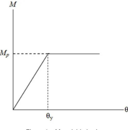
A perfectly–plastic material assigned to plastic hinge zones is used in this study to consider material non–linear effects. In an elastic perfectly–plastic material, the effects of strain hard-ening are neglected. It further implies that once the yield momentMp is reached, the material
yields and cannot withstand further stress. The material constitutive behavior is shown in Fig. 1.
Figure 1 Material behavior
The yield moment is often defined through a yield criterion. A variety of yield criteria have been introduced in structural engineering. For the steel elements in this paper, the AISC– LRFD[1] criterion considering bending moment and axial force interaction is determined as follows:
Mpc=⎧⎪⎪⎨⎪⎪ ⎩
Mc (1−2∣QQ∣c) f or ∣Q∣
Qc
<0.2
9
8Mc(1−
∣Q∣
Qc) f or ∣Q∣
Qc
≥0.2 (6)
in which, Mc=φbZFy,Mpcis the reduced plastic moment capacity in the presence of axial
force (Qc=φcQn);φbandφc are the bending and axial resistance factors respectively;Fy is the
yield stress, andZ is the plastic section modulus.
In inelastic analysis, the tangent stiffness matrix introduced in section 2.2 has to be modi-fied. A detailed discussion on the inelastic analysis can be found in[16].
3 THREE–POINT METHOD
Multipoint methods without memory are methods that use new information at a number of points. It is an efficient way of generating higher order methods free from second and higher order derivatives. One classical problem in numerical analysis is the solution of nonlinear equations wheref(x) = 0. Efficiently finding zeros in a single variable nonlinear equation is an interesting and very old problem in numerical analysis with many applications to structural engineering.
The three–point iteration scheme for solving nonlinear equations is expressed as follows:
⎧⎪⎪⎪⎪ ⎪⎨ ⎪⎪⎪⎪⎪ ⎩
yn= xn− f(xn)
f′(xn)
zn= yn−ff′((yyn)n)
xn+1=ϕ(xn)=zn−ff′(zn)
(zn)
(n=0,1, ...) (7)
It can be showed that the efficiency index of this approach is√2=1.4142 which is equal to
that of Newton’s method. In fact, Newton’s method is applied three times. Recently, Dzunic et al.[12] have modified the above scheme in order to improve the computational efficiency of the iterative method. The derivatives f′
(y)andf′
(z) are approximated using following relations:
f′ (yn)≈
f′ (xn) p(sn) , f
′ (zn)≈
f′ (xn) q(sn, tn)
(8)
in which
sn= f(yn) f(xn), tn=
f(zn)
f(yn) (9)
It should be noted that the quantities s and t do not require new information since they are expressed by the already calculated quantities. Now the three–point scheme (7) has the form:
⎧⎪⎪⎪⎪ ⎪⎨ ⎪⎪⎪⎪⎪ ⎩
yn= xn−ff′((xxn)n)
zn= yn−p(sn)ff′((yxnn))
xn+1=ϕ(xn)=zn−q(sn, tn)ff′((zxn)n)
(n=0,1, ...) (10)
where p andq are arbitrary real functions with Taylor’s series of the form:
p(s)=1+2s+2s2+γs3+... (11)
q(s, t)=1+2s+t+3s2+4st+γs3+... (γ ∈R) (12)
It can be proved that the family of three–point methods (7) has the order eight, if p and q conditions (11,12)[12]. Since the total number of function evaluations per iteration of the method (3) is four, the efficiency index of proposed method is √4
8 = 1.6818 which is better
3.1 Choice of functions p and q
The functions p and q have been searched in a general rational form:
p(s)=1+(2−β)s(1+s)
1−βs(1−s) (13)
q(s, t)= 2+(6+γ1)s
2
+2(t+γ2)+s(4+2γ1+γ3t) 2+2γ1s−3γ1s2+γ2t+(γ3−2γ2−2γ1−8)st
(14)
which satisfies conditions given in Eqs. (11,12) and its parameters (β, γ1, γ2, γ3) have been selected using trial and error approach.
In this way many different functions can be generated. In this paper functions p1thru p3 and q1 thruq4 have been chosen from reference[12]. They are mentioned in the following:
p1(s)=1+2s+2s 2
(15)
p2(s)= 1
1−2s+2s2 (16)
p3(s)=
1+s+s2
1−s+s2 (17)
q1(s, t)=1+2s+t+3s 2
+4st (18)
q2(s, t)=(2s+ 5 4t+
1 1+s+34t)
2
(19)
q3(s, t)=
1−4s+t
(1−3s)2
+2st (20)
q4(s, t)=
1
1−2s+s2+4s3−t (21)
Another function for p and q is introduced in the proposed method, respectively:
p4(s)=
1−3s−3s2
1−5s+5s2 (22)
q5(s, t)=
2+2t+s(t−8)
2−12s+18s2+5st (23)
4 THREE–POINT SCHEME IN STRUCTURAL ANALYSIS
The three–point technique can be applied to analysis of structures with complex behaviors, including unloading, snap–through, elastic post–buckling and inelastic post–buckling analyses. In this paper a modified normal flow algorithm[21] is used to trace the equilibrium paths. The theory of this method is described in the following sections.
4.1 Modified normal flow algorithm
If i is the step number, j is the number of the modifying iteration, and the total load on the structure is {P}ji, or its equivalent, the product of a total ratio λjtoti and a given reference external load {Pref} is applied through a series of load increments. Mathematically, this is
written as:
{P}ji =λj
toti{Pref} (24)
A detailed discussion and the process of the normal flow algorithm have been represented in reference[21].
A nonlinear system of equilibrium equations can generally be formulated as follows:
J(λj−1
i , δ j−1
i )S j
i =−F(λ j−1
i , δ j−1
i ) (25)
whereJ(λj−1
i , δ j−1
i )is the Jacobian matrix of orderN×(N+1)and S j
iis the Newton–Raphson
step size which is found through the following relationship:
J(λj−1
i , δ j−1
i )=[
∂F(λji−1, δji−1) ∂λ
∂F(λji−1, δji−1)
∂δ ] (26)
In the normal flow algorithm, the Newton–Raphson step size is the minimum solution of the system of Eq. (25) which is unique among an infinite number of solutions obtainable[21]. A particular solution {V} should be obtained from:
[τ]ji−1{V}=∆λij{Pref}−{∆Q}ji−1 (27)
in which:
∆λji =−[{δI}
j i]
T{∆δ R}ji [{δI}ji]T{δI}j
i
(28)
where{∆Q}ij−1is the vector of the unbalanced forces,{δI}jiis vector of tangential displacement
in the converged point; and{∆δR}ji is the vector of unbalanced displacements such that,
{∆Q}ji−1={F}j
i− ⎛
⎝λconvtoti−1+λ
j=1
i +∑ j=2
∆λj−1
i ⎞
⎠{Pref} (29)
in which{F}ji is the vector of resultant internal forces at the nodes. The vector of unbalanced force is computed through the following system of equations:
[τ]ji−1{∆δR}ji =−{∆Q}j −1
Using the following equation the minimum solution of the norm is calculated:
{∆δ}ji ={V}−{V}
T{δ I}ji ∥δI∥
2 {δI}
j
i (31)
in which {δI}ji is the tangential displacement. A direct method of updating is adopted such
that, the load increment is related to the number of iterations. Also sign of determinant of the tangential stiffness matrix of the previous step can be computed through the following relationship:
λji+1=±λ
j i(
JD JM)
γ
(32)
where exponentγis a certain number,JD is the number of iterations assumed at the beginning
of the calculations and JM is the number of iterations performed in the previous step.
4.2 Algorithm of nonlinear analysis based on three–point method
Here, a general flow chart for the iterative process is presented as follows: Step 1) Initialization of variables and parameters.
Step 2) Input first incremental load, λ1
1,JD,JM, boundary conditions, connectivity,
mate-rial properties and structural geometry.
Step 3) For the first iteration at each increment step i: 3.1 Form the system tangent stiffness matrix [τ]0i. 3.2 Determine {V}using[τ]ij−1{V}={Pref}.
3.3 Compute the load increment parameter λ1
i; fori = 1, setλ
1
i =λ
1
1; for i≥2 use Eq. (32).
Step 4) Compute the element force vector. Update the tangent modulus accounting for inelastic effects. Update global stiffness matrix
Step 5) Solve for tangential displacement:[τ]ji−1{δI}ij ={Pref}. Solve for{∆δR}ji from Eq.
(30).
Step 6) Calculate {d1}ji ={δ}ji+{∆δR}ji.
Step 7) Update global nodal displacements and determine the unbalanced load: {∆Qd1}ji = {P}ji−{Fd1}ji.
Step 8) Compute s:
sji = {∆Q}
j i T
{∆Qd1}ji {∆Q}jiT{∆Q}ji
(33)
and constructp(s).
Step 9) Determine the new node locations:
{d2}
j
i ={d1}
j
i+pi[τ] −1
{∆Qd1}ji (34)
{∆Qd2}ji={P}ji−{Fd2}ji.
Step 11) Compute t:
tji = {∆Qd1}
j i T
{∆Qd2}ji {∆Qd1}jiT{∆Qd1}ji
(35)
and construct q(s,t).
Step 12) Determine the new node locations:
{δ}ji+1={d2}
j
i+qi[τ] −1
{∆Qd2}ji (36)
Step 13) Determine the load increment parameter using Eq. (28) and update it. Step 14) Check the convergence criteria by the following relation:
[{δ}ji]T{∆δ}ji [{δ}ji]T{δ}j
i
≤ε (37)
where εis a predefined error in the course of calculations.
5 NUMERICAL RESULTS
A computer program is developed in this study which incorporates the three–point algorithm. CPU times taken by calculation process can be measured conveniently when the corresponding command prompt on the screen is set. All examples are solved using a 32–bit Pentium 2.00 GHz processor (Dual core). To examine the performance of the method proposed here and to evaluate the results obtained, some examples are presented in this section. Newton–Raphson method and other sub–stepping algorithms including three–point method are applied to three cases of elastic, elastic post–buckling (EPB), and inelastic post–buckling (IPB) analyses of typical and well–known structures. A predefined tolerance of ε=10−5
is also assigned to all cases defined in the analysis. Parameters r, X1, X2 are assigned fixed values as r = 0.4, X1 = 50 and X2 = 100[25] and remain unchanged throughout the analysis. Newton–Raphson method or three point procedure are used in inner steps of the path-following algorithms. Comparison between these two approached are listed in the following Tables.
5.1 Example 1
The geometric dimensions of the geodesic dome truss shown in Fig. 2 are adopted from Ramesh and Krishnamoorthy[19].
This truss has a total of 61 nodes and 156 members with identical cross–section (A = 6.5 cm2
and I = 1 cm4
) located at the outer supports are restrained as pin supports. A concentrated vertical load of P = 8 kN is applied to the center of dome as shown in Fig. 2. Parameters of Eq. (32) are selected such that∆λ11 = 0.01, λmax = 0.5, γ = 0.1, JD = 10,
Jmax=100. The elevation of the truss is defined by the following equation:
Figure 2 Geodesic dome truss, dimensions are given in cm
The material properties are E = 6895 kN/cm 2
and Fy = 400 kN/cm 2. The load–
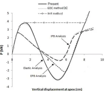
displacement curves obtained from four cases of analysis are shown in Fig. 3.
Table 1 presents a summary of the CPU time taken for application of classic Newton– Raphson method and the three–point method in three cases of analysis for various path– following methods.
Table 1 Comparison of CPU time (sec) for example 1
Normal flow GDC method Arc-length method MRD method
algorithm[8] [6] [5] [12]
Analysis N-R three-point N-R three-point N-R three-point N-R three-point Elastic 27.5305 18.9418 28.1102 19.4392 29.4565 20.0414 28.9681 19.1125
EPB 34.6207 20.8456 36.3418 21.7725 37.2304 23.3566 35.8653 21.0582 IPB 48.0764 25.6491 50.1317 27.0136 51.1186 27.9652 49.0037 46.0125
Table 2 Comparison of number of iterations for example 1
N-R method used in Three–pint method used in decrease normal flow algorithm normal flow algorithm percentage
135 80 40.74
Figure 3 Load–displacement curves of geodesic dome truss at apex 5.2 Example 2
A circular dome truss taken from reference[25] is shown in Fig. 4. This structure has 168 elements and 73 nodes for a total of 147 degrees–of–freedom. The structures is subjected to a vertical loadP = 500 kN at the apex. The out–of–plane motion has been constrained with pin supports appended to each end of the truss.
The cross–sectional properties for area (A) and moment of inertia (I) are 50.431 cm2 and 52.94 cm4
respectively for all members. The elastic modulus (E) for all members is 2.04×10⁴ kN/cm2
and Fy= 25 kN/cm2.
For Eq. (32), parameters∆λ1
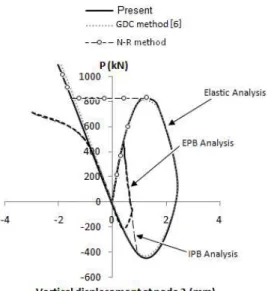
1=0.01,λmax=2,JD=5,Jmax=100,γ =0.1 are selected. Fig. 5 illustrates the numerical responses obtained from the proposed formulation for four cases of analyses in a manner similar to Example 1. The comparisons between the results of applying the two methods (Newton–Raphson and three–point) are listed in Table 3 and Table 4.
Table 3 Comparison of CPU time (sec) for example 2
Normal flow GDC Arc-length MRD
algorithm[21] method [6] method[20] method[7]
Analysis N-R three-point N-R three-point N-R three-point N-R three-point Elastic 26.8613 14.8848 27.1618 15.0435 27.8791 15.0561 27.6411 15.2743
EPB 62.9116 34.6559 65.0505 34.2702 65.3090 35.2936 64.2039 36.1415 IPB 87.2952 47.6567 90.6501 48.7870 89.1506 46.5981 88.6908 48.3487
Fig. 5 shows the significant shortcoming of Newton–Raphson method in passing limit point.
Table 4 Comparison of number of iterations for example 2
N-R method used in Three–pint method used in decrease normal flow algorithm normal flow algorithm percentage
187 101 45.98
Figure 4 Circular dome truss solved in example 2 (dimensions are given in cm)
5.3 Example 3
Schewdeler’s truss[14], shown in Fig. 6 having 264 elements and 97 nodes with pin supports at the outer nodes provides a good opportunity to evaluate the efficiency of the method discussed herein.
Figure 6 Schewdeler’s dome truss, dimensions are given in cm
The axial stiffness (EA) for all members is taken as 640×103 kN,Fy = 25 kN/cm 2, and
I = 30.04 cm 4
. The external loading was a typical equipment loading of the magnitude P = 50 kN at the crown node. For Eq. (32) parameters∆λ1
1= 0.01, λmax = 1, γ = 0.1,JD =2, Jmax=100 are used.
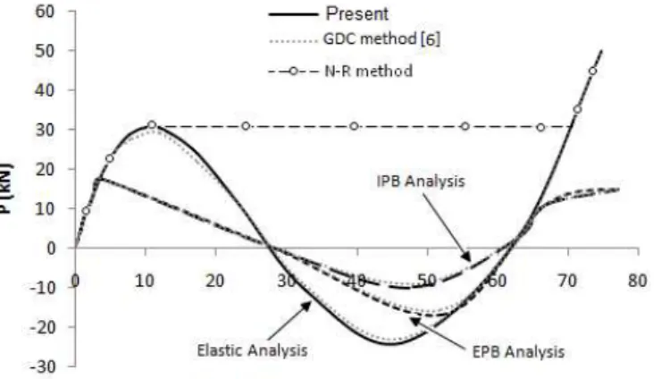
Fig. 7 shows variation of vertical displacement at central node with the load P obtained in three cases of analysis.
When each of these four cases is analyzed using the four different iteration algorithms, a total of 16 sets of results are obtained. For the purpose of this study, it is interesting to investigate the summary of the results and compare the computational time taken by all of methods. Table 5 provides a summary of all results for convenience.
It is important to note that all computations were carried out with the smallest step possible and with high precision.
Table 5 Comparison of CPU time (sec) for example 3
Normal flow GDC Arc-length MRD
algorithm[21] method[6] method[20] method [7]
Analysis N-R three-point N-R three-point N-R three-point N-R three-point
Elastic 115.6921 56.3722 119.8305 58.25922 119.2752 58.08051 120.3278 58.69566
EPB 144.2047 80.7417 148.0804 82.40212 147.7251 82.1779 146.1286 83.26964
IPB 184.1164 104.4722 186.7869 103.5209 188.9921 106.3163 193.1962 107.9256
Table 6 Comparison of number of iterations for example 3
N-R method used in Three–pint method used in decrease normal flow algorithm normal flow algorithm percentage
212 113 46.69
From Table 6, the minimum number of iterations is associated with the three–point scheme.
5.4 Example 4
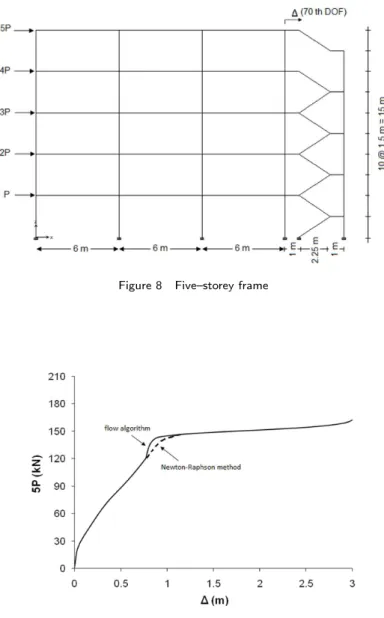
The last example shown in Fig. 8 has been analyzed by Spiliopoulos and Patsios[24]. For all members E = 220000 kN/m 2
. Section properties for columns are I = 0.000313 m 4 , A = 0.022 m2
. Beam sections (including the inclined members) given as: I = 0.0000249 m4 ,A = 0.00543 m2
. The load increment, ∆P,is 0.795 kN andP = 31.80 kN. The frame was analyzed using the three–point method developed in this paper.
Fig. 9 shows the load–displacement curve obtained by applying the method developed in the present study and Newton–Raphson method, respectively.
The results show that the number of iterations and the computing time used in deploying the classic Newton–Raphson approach is more than that used by applying the developed method. The results are presented in Table 7.
Table 7 Comparison of CPU time (sec) for example 4
Analysis/Method elastic EPB IPB
N-R 6.9654 8.7566 10.1735
Three–point 4.3016 5.00684 5.7323
Figure 8 Five–storey frame
Figure 9 Load–displacement curve for five–storey frame
Table 8 Comparison of number of iterations for example 4
N-R method used in Three–pint method used in decrease normal flow algorithm normal flow algorithm percentage
6 CONCLUSIONS
This paper provides a simple and accurate high order approach which can be used in complex structural analysis. A mathematical method which was named three–point method can reduce the global computational time of nonlinear analysis and number of iterations by near 40– 50% when compared with other more commonly used methods. In the three–point method using two functions, the acceleration of convergence was increased. Several functions and a new function were proposed and results were compared with those obtained by deploying the classic Newton–Raphson method. A computer program was developed to numerically solve a system of nonlinear equations in an incremental form. The numerical examples represented a good compromise between reducing the computing time, reducing the number of the iterations and obtaining results sufficient accuracy.
Acknowledgments The authors would like to extend their appreciation to Prof. Miodrag S. Petkovic for discussions and guidance regarding the three-point method. The authors would also like to thank Dr. Gary S. Prinz for providing language help.
References
[1] Load and resistance factor design specification for structural steel buildings. American Institute of Steel Construction, Chicago, 2nd ed edition, 2005.
[2] D.K.R. Babajee and M.Z. Dauhoo. An analysis of the properties of the variants of newton’s method with third order convergence.Applied Mathematics and Computation, 183(1):659–684, 2006.
[3] D.K.R. Babajee, M.Z. Dauhoo, M.T. Darvishi, and A. Barati. A note on the local convergence of iterative methods based on adomian decomposition method and 3-node quadrature rule. Applied Mathematics and Computation, 200(1):452–458, 2008.
[4] K.J. Bathe and A.P. Cimento. Some practical procedures for the solution of nonlinear finite element equations.
Computer Methods in Applied Mechanics and Engineering, 22(1):59–85, 1980.
[5] K.J. Bathe and E.N. Dvorkin. Automatic solution of nonlinear finite element equations. Computers and Structures, 17(5):2110–2116, 1983.
[6] E.L. Cardoso and J.S.O. Fonseca. The gdc method as an orthogonal arc-length method. Communications in Nu-merical Methods in Engineering, 23(4):263–271, 2006.
[7] S.L. Chan. Geometric and material nonlinear analysis of beam-columns and frames using the minimum residual displacement method. International Journal for Numerical Methods in Engineering, 26(12):2657–2669, 1988.
[8] C. Chun. A new iterative method for solving nonlinear equations.Applied Mathematics and Computation, 178(2):415– 422, 2006.
[9] M.J. Clarke and G.J. Hancock. A study of incremental-iterative strategies for nonlinear analysis. International Journal for Numerical Methods in Engineering, 26(7):1365–1391, 1990.
[10] M.A. Crisfield. Nonlinear Finite Element Analysis of Solids and Structures, volume 1. John Wiley and Sons, 1991.
[11] M.A. Crisfield and J. Shi.A review of solution procedures and path–following techniques in relation to the nonlinear finite element analysis of structures. Springer, 1990. Non-linear Computational Mechanics-The State of Art.
[12] J. Dzunic, M.S. Petkovic, and L.D. Petkovic. A family of optimal three-point methods for solving nonlinear equations using two parametric functions.Applied Mathematics and Computation, 217(19):7612–7619, 2011.
[14] M. Greco, F.A.R. Gesualdo, W.S. Venturini, and H.B. Coda. Inelastic post-buckling analysis of truss structures by dynamic relaxation method. Finite Elements in Analysis and Design, 42(12):1079–1086, 2006.
[15] C.D. Hill, G.E. Blandford, and S.T. Wang. Post-buckling analysis of steel space trusses.ASCE Journal of Structural Engineering, 115(4):900–919, 1989.
[16] A. Kassimali. Large deformation analysis of elastic-plastic frames. ASCE Journal of Structural Engineering, 109(8):1869–1886, 1983.
[17] L.D. Petkovic and M.S. Petkovic. A note on some recent methods for solving nonlinear equations. Applied Mathe-matics and Computation, 185(1):368–374, 2007.
[18] M.S. Petkovic and L.D. Petkovic. Families of optimal multipoint methods for solving nonlinear equations: a survey.
Applicable Analysis and Discrete Mathematics, 4(1):1–22, 2010.
[19] G. Ramesh and C.S. Krishnamoorthy. Inelastic postbuckling analysis of truss structures by dynamic relaxation method.International Journal for Numerical Methods in Engineering, 37(21):3633–3657, 1994.
[20] E. Riks. An incremental approach to the solution of snapping and buckling problems.International Journal of Solids and Structures, 15(7):529–551, 1979.
[21] H. Saffari, M.J. Fadaee, and R. Tabatabaei. Nonlinear analysis of space trusses using modified normal flow algorithm.
ASCE Journal of Structural Engineering, 134(6):998–1005, 2008.
[22] H. Saffari and I. Mansouri. Non–linear analysis of structures using two-point method. International Journal of Non–Linear Mechanics, 46(6):834–840, 2011.
[23] H. Saffari, N.M. Mirzai, I. Mansouri, and M.H. Bagheripour. An efficient numerical method in second-order inelastic analysis of space trusses. ASCE Journal of Computing in Civil Engineering, 2012. doi:10.1061/(ASCE)CP.1943-5487.0000193.
[24] K.V. Spiliopoulos and T.N. Patsios. An efficient mathematical programming method for the elastoplastic analysis of frames. Engineering Structures, 32(5):1199–1214, 2010.
[25] H. Thai and S. Kim. Large deflection inelastic analysis of space trusses using generalized displacement control method.
Journal of Constructional Steel Research, 65(10-11):1987–1994, 2011.
[26] G.A. Wempner. Discrete approximations related to nonlinear theories of solids.International Journal of Solids and Structures, 7(11):1581–1599, 1971.
