Fiabilitate si Durabilitate - Fiability & Durability No 1/ 2015 Editura “Academica Brâncuşi” , Târgu Jiu, ISSN 1844 – 640X
70
THE GEOMETRY OF THE SPATIAL FOUR-BAR MECHANISM
AND OF ITS PARTICULAR FORMS
Păun ANTONESCU, PH.D. „POLITEHNICA” UNIVERSITY OF BUCHAREST,
Ovidiu ANTONESCU, PH. D. „POLITEHNICA” UNIVERSITY OF BUCHAREST, [email protected]
Constantin BREZEANU, SILCOTUB S. A. (TENARIS GROUP) CĂLĂRAȘI, [email protected]
ABSTRACT: starting from the rssr spatial four-bar mechanism, this paper analyses the most significant particular cases for which the specific transfer functions are written in comparison to the respective function deduced in the general case. From among the particular cases of the spatial mechanisms, the authors mention the oscillating washer mechanism and the cardan mechanism, demonstrating that spherical mechanisms can be obtained as the simplified variants in which the spherical joints may be replaced by simple rotation joints. For the spherical mechanism, the respective transfer functions have been determined as the simplest particular forms of the transfer function achieved by the rssr spatial four-bar mechanism.
KEYWORDS: spatial four-bar mechanism, spherical joint, transfer function, cardan mechanism
1. GENERAL CONSIDERATIONS
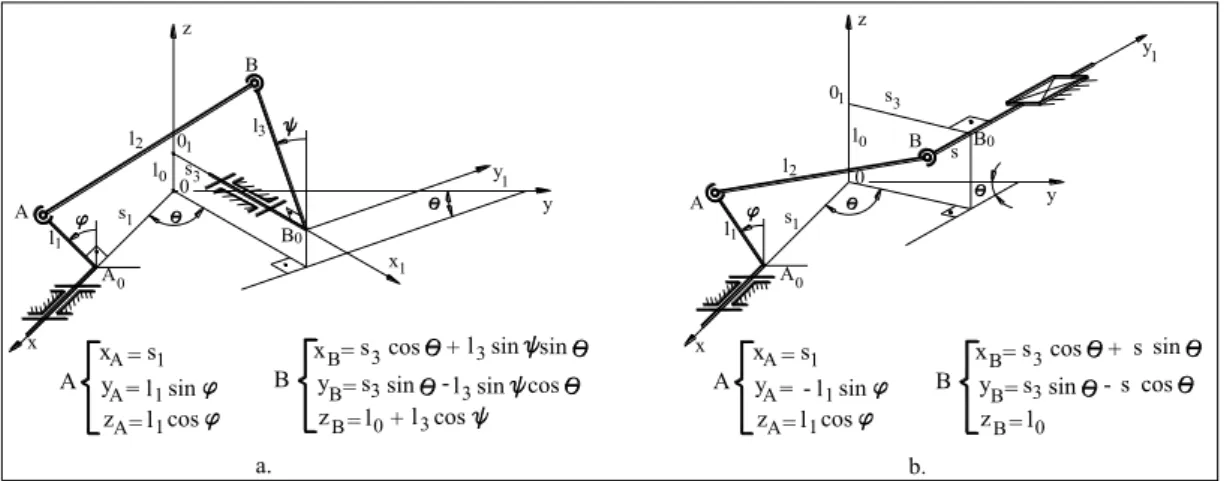
The bar spatial mechanisms rssr (fig. 1a) and rsst (fig. 1b) are used in numerous fields of manufacturing engineering such as: sewing machines in the textile industry, agricultural equipment, hydraulic pumps and engines, wind screen wiper mechanisms.
These mechanisms consist of a minimum number of kinematic elements, are some of the simplest spatial mechanisms [1, 2] and have the advantage that they can achieve, for a small gauge, the transmission and transformation of the rotation motion between the in and out elements whose axes are displaced randomply in space.
x 1 l
l l
A
2 3
B
0 A
1 y
y
1 x 0
B0 s
s1 3 01
z
l0
l1 A
1 s
0
0 A
B 1 s
0 l0 l2
0 3 z
B
y1
y
x
s
a. b.
x y z
A 1 A 1 A 1
= s = l sin = l cos A
x = s y = z = l
B 3
0
cos +
-l3sin sin B
B s3sin l3sin cos B + l3cos
A xA=s1
y A= l1sin cos z lA= 1
-+
3
= x s cos
y B
= z lB 0
sin = s
B 3 B
-sin cos s s
Fiabilitate si Durabilitate - Fiability & Durability No 1/ 2015 Editura “Academica Brâncuşi” , Târgu Jiu, ISSN 1844 – 640X
71
As compared to other types of spatial mechanisms with upper kinematic couplings (with spatial cams or with conical / auger gears), bar spatial mechanisms are made of lower kinematic couplings (cylindrical and spherical), which offers simpler technical solutions (requiring less expensive technologies), and has higher reliability in difficult working conditions.
Starting from the general case of the rssr spatial quadruple mechanism, the paper deals with the classical particular cases [2] as well as with the new ones [1, 7]. These mechanisms have apparently no geometrical or construction characteristics in common.
Thus, the transmission functions for each type of spatial mechanism can be easily obtained from the transmission function deduced in the general case of the rssr spatial mechanism [1, 2, 6]. If we take the general case of the rssr spatial mechanism (fig. 1a), as written out in the diagram, the transmission function can be written as [2, 6]:
0 ) sin sin cos cos
(cos cos
sin cos
sin 2 3 4 5
1
0a a a a a
a (1)
The relation (1) is a function of the type F(,)0, where the angles and place the crank 1 (drive element) and the equalizing bar 3 (driven element) as to the axis oz (fig. 1a). If we use the notations in the kinematic diagram (fig. 1a), the coefficients in the equation (1) can be expressed as follows:
cos 2 1 3
2 3 2 1 2 3 2 2 2 1 2 0
0 l l l l s s s s
a ;
1 0 2 3
1
1 2l s sin ; a 2l l
a ; (2)
3 1 5 3 0 4 3
1
3 2s l sin ; a 2l l ; a 2l l
a .
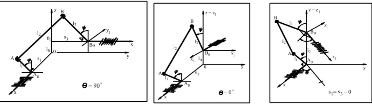
2. The rssr mechanism with orthogonal axes ( 900)
In the particular case of 900(fig. 2) the o1b0 axis is parallel to the oy axis, so that the
crank 1 and the equalizing bar 3 rotate in perpendicular planes.
x l1
A s1
0
0
A
B x1
1 s
0 l0 l2
0 3
l3
z B
y
1
y
= 90o
x 1 l
0 A
l l
A 2
3 B
1 y z = z1
y 1
x B0
0 l0
s1
x A
1 l A
0 1 l
l2 3 B
y z = z1
y 1 x l0
B0
o
s = s = 01 3 = 0
Fig. 2. Kinematic diagram of the rssr spatial mechanism when 900,00,s1s3 0
The coefficients a0,a1 and a3 which depend on the angle therefore become:
2 3 2 1 2 3 2 2 2 1 2 0
0 l l l l s s
a ;
3 1 1 2l s
Fiabilitate si Durabilitate - Fiability & Durability No 1/ 2015 Editura “Academica Brâncuşi” , Târgu Jiu, ISSN 1844 – 640X
72
This mechanism where the in and out axes are perpendicular (fig. 2) is called an orthogonal spatial quadrangle [1, 5]. For 900 the transmission function (1) is written:
0 cos cos cos
sin cos
sin 2 3 4 5
1
0a a a a a
a (4)
3. THE RSSR MECHANISM WITH PARALLEL AXES ( 00)
When 00the rotation axes of the crank 1 and the equalizing bar 3 become parallel (fig. 2) when we can consider s3 0, so that the point b0 is on the oz axis and the equalizing
bar 3 rotates in the yoz plane.
For 00,1800the a1 and a3 coefficients are null, and the a0 coefficient is
2
3 1 2 3 2 2 2 1 2 0
0 l l l l (s s )
a (5)
This particular case (fig. 2) corresponds to the plane-parallel of the elements 1 and 3 whose rotation axes are parallel. The transmission function (1) coincides in this case (fig. 2) to the one of the plane mechanism:
0 ) cos( cos
cos 4 5
2
0a a a
a (6)
4. THE RSSR MECHANISM WITH s1s3 0
The two rotation axes of the crank 1 and of the equalizing bar 3 are displaced randomly in space (fig. 2), but the points a0 and b0 are situated on the oz axis. Since s1s30, the a1 and
3
a coefficients are null (a10,a30), and the a0 coefficient can be inferred from (5)
2 3 2 2 2 1 2 0
0 l l l l
a (7)
The transmission function (1) becomes in this case
0 ) sin sin cos cos
(cos cos
cos 4 5
2
0a a a
a (8)
For the orthogonal spatial mechanism ( 900), the transmission function (8) becomes 0
cos cos cos
cos 4 5
2
0a a a
a (9)
The formula (9) can be also inferred from (4) if we introduce the conditions s1s30.
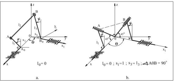
5. THE RSSR MECHANISM WITH l00
The condition l0 0 imposes the concurrency of the rotation axes of the in and out elements (fig. 3), which corresponds to the geometrical condition of spherical mechanisms.
From the relations (2) null values for the a2and a4coefficients are obtained (a2a4 0), and for the coefficient a0we infer the expression
cos 21 3 2
3 2 1 2 3 2 2 2 1
0l l l s s s s
Fiabilitate si Durabilitate - Fiability & Durability No 1/ 2015 Editura “Academica Brâncuşi” , Târgu Jiu, ISSN 1844 – 640X
73
B
l
A l
x
y z
A
B y
s l
s
x 0
2
1
3 3 1
0
0 1
1
0 z
B
y
x1 A
x
1
l
45o 45o
a. b.
l = 0 ; s =1 ; s = l A0B = 90o
l = 00 0 1 3 3;
Fig. 3. Kinematic diagram of the rssr mechanism with concurrent axes
For the transmission function (1) we obtain the expression
0 ) sin sin cos cos
(cos sin
sin 3 5
1
0a a a
a (11)
In the particular case when the oa and ob lines are perpendicular (fig. 3b), we have the following relation between the specific liniar lengths of the mechanism
2 2 2 3 2 1 2 3 2
1 l s s l
l (12)
This condition determines a much simpler expression for the a0coefficient
cos 2 1 3
0 s s
a (13)
Considering the formulas of the a1,a3and a5 coefficients of (2) versus the formula of the
0
a coefficient in (10) or (13), it is inferred that, when s1l1;s3 l3, the transmission function (11) becomes:
0 ) sin sin 1 ( cos ) sin (sin
sin cos
cos (14)
Which shows that the function F(,)0 no longer depends on the liniar parameters of
the mechanism, this being specific to the spherical mechanism.
Indeed, in this particular case, the s type spherical joints in points a and b (fig. 3a) can be replaced by r type cylindrical joints (fig. 3b).
For the orthogonal spherical mechanism ( 900), the transmission function (14) becomes 0
sin sin
cos
cos (15)
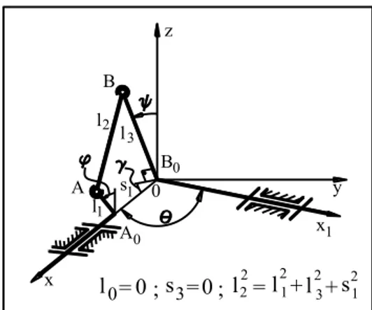
6. THE RSSR MECHANISM WITH l00,s1s30
This particular case of the spatial mechanism corresponds to the simple spherical mechanism of the crank-equalizing bar type (fig. 4).
If we take into account the above mentioned geometrical conditions (fig. 4), the
4 3 2 1,a ,a ,a
a coefficients are null, and the equation of the transmission function is expressed in a simplified form:
0 ) sin sin cos cos (cos
5
0a
Fiabilitate si Durabilitate - Fiability & Durability No 1/ 2015 Editura “Academica Brâncuşi” , Târgu Jiu, ISSN 1844 – 640X
74
l = 0 ; s = l22 l
2 1
2 3
2 1
+l + s
0 3 0 ; =
0
l0= ; s1=s3= 0 z
x
y B0
x1 0
1
y
2
l
1
l l3
B
A
0
B
1
l 0
x
2
l l
A
3
B
y
1
x z
s
A0
1
Fig. 4. Spherical rssr mechanism Fig. 5. Cardan rssr mechanism
Where the a0 and a5 coefficients are expressed:
2 3 2 2 2 1
0 l l l
a ; a5 2l1l3 (17)
When the x and x1 axes (fig. 4) are perpendicular, we can infer the transmission function
from (16) for 0 as below
a0a5coscos 0 (18)
7. THE RSSR MECHANISM WITH l0 0,s30,a0 0
For these particular values, between specific geometrical parameters we can infer from (2) the relation
2 3 2 1 2 1 2
2 l s l
l (19)
Which corresponds to the kinematic scheme of the rssr mechanism (fig. 5) when the ab0b
triangle is a right triangle, that is (AB0B)900.
If on the kinematic scheme (fig. 5) we write (A0B0A) we can write the relation
tg s
l1 1 , so that the coefficient a1 of (2) becomes
tg l l
a1 21 3sin (20)
The other coefficients of the transmission function (1) are a2 a3 a4 0 and a5 2l1l3, which determines for the implicite function F(,)0the following particular form
0 ) sin sin cos cos
(cos sin
sin tg (21) In which we have only constant angular parameters (,) together with variable angular parameters (,).
Fiabilitate si Durabilitate - Fiability & Durability No 1/ 2015 Editura “Academica Brâncuşi” , Târgu Jiu, ISSN 1844 – 640X
75
If we consider the case of perpendicular axes with this mechanism (fig. 5) ( 900), this corresponds to the spherical mechanism with eqalizing bar of the oscillating washer type [1, 7]. The transmission function is obtained from (21) in its simple form:
tg cos
tg (22)
8. THE RSSR MECHANISM WITH l0 0,s1 s3 0,a0 0
For the new geometrical conditions imposed to the spatial rssr mechanism (fig. 6) the relation (19) is written l22 l12l32.
which corresponds to the constant 900 angle between segments a0a and a0b (fig. 6).
l1
x
l2
A B
l3
y x1 y1
A0
1
z = z
l
0
l =0; s3=0; 2=l 23 2
l + 1 2 s1=
Fig. 6. Kinematic diagram of the cardan rssr mechanism
The spherical mechanism obtained (fig. 6) is of the cardan type, where the transmission function is inferred from the equation (16) for a00as follows:
0 sin sin cos cos
cos (23)
From equation (23) we obtain the expression
cos 1 tg
tg (24)
In this case we can replace the spherical couplings in a and b (fig. 6) by rotation cylindrical couplings, just like with the classical cardan spherical mechanism.
we should mention that formula (23) represents the transmission function of the mechanism known as simple cardan coupling, its expression being different from the one known and given in the papers [3, 4, 7].
This is due to the way in which the and angles are measured, so that in this case the two angles are measured against the same direction parallel to the a0z axis that is common to both
cartesian reference points a0xyz and a0x1y1z1 (fig. 6).
We should also notice that, if the and angles are measured against the a0y axis and the
a0y1 axis (fig. 6), the transmission function is obtained as follows [3, 8]: tgtg cos
If theangle is measured against the a0y axis, and the angle is measured against the a0z1
axis (fig. 6), the transmission function becomes:
l0 =0, s1=s3=0, 2 3 2 1 2
2 l l
l ,
A
B
A0 A’
B’
x
x1
y y1
z, z1
l2
l1
l3
l1
l3
.
.
l3
l3
l1
B1
A1
Fiabilitate si Durabilitate - Fiability & Durability No 1/ 2015 Editura “Academica Brâncuşi” , Târgu Jiu, ISSN 1844 – 640X
76
cos 1 ctg
tg (25)
With cardan transmissions, the angle(between the axes a0x and a0x1 ) is an obtuse
( 900), therefore cos 0. If in this case we consider the acute angle 1800 (fig. 6), the transmission function (25) can be written in its well-known explicite form [1, 4, 7, 9]:
cos
tg
tg (26)
9. Conclusions
Starting from the representation of the kinematic diagram of the rssr spatial mechanism, in an axonometric projection (fig. 1a), in the paper we infer the expression of the transmission function F(,)0 in its implicite form (1), of which specific forms are obtained for different cases.
Of the specific variants of the rssr spatial quadruple mechanism, the authors mention in particular spherical mechanisms, known as crank – equalizing bar spherical mechanism (fig. 7), called sherical mechanism with oscillating washer and the crank – crank spherical mechanism (fig. 8) called cardan (coupling) mechanism.
It is proven that these two spherical mechanisms, which have multiple applications in manufacturing engineering, can be obtained as simplified variants of the rssr quadruple mechanism (fig. 1a), in which spherical couplings are replaced by rotation cylindrical couplings. The cardan type spherical rssr quadruple mechanism can be achieved as two
parallel chains (fig. 6), with equal length ab and a’b’ reciprocating rods.
REFERENCES
1. Antonescu, P., Mechanisms - Structural and Kinematic Calculation, Polyt. Inst. Press, Bucharest, 1979;
2. Luck, K., Modler, K-H., Einfache raumgetribe für getribetechnishe grundaufaben, Wiss. ZDTU. Dresden, 1978;
3. Manafu, V., Theory of Mechanisms and Machines. Structure and kinematics. The Technical Publishing House, Bucharest, 1959;
4. Autorenkollektiv, Getriebetechnik Lehrbuch, VEB Verlag Technik, Berlin, 1969; 5. Antonescu, P., Contributions to the Graphic Synthesis of Spatial Mechanisms, Ph.D.
Thesis, The Polytechnics Institute Press, Bucharest, 1969;
6. Alexandru, P. and others., Mechanisms Vol. II, Synthesis, Braşov University Press, 1984;
7. Dudiţă, F., Cardan Transmissions, The Technical Publishing House, Bucharest, 1966;
8. Pelecudi, Chr. and others, Mechanisms, E. D. P. Bucharest, 1985;
9. Antonescu, P., On the Specific Cases of the Spatial Quadruple Mech., SYROM’89, vol. II.1, p. 1-10;
10.Antonescu, P., Mechanisms, Printech Publishing House, Bucharest, 2003.
11.Vişa, I. and others, Functional Design of Mechanisms, Classical and Modern Methods,