Comparative structural response of two steel bridges constructed 100 years apart
Humberto Varuma*, Romain Sousaa, Walter Delgadoa, Catarina Fernandesa, Anı´bal Costaa, Jose M. Jarab,Manuel Jaraband Jose J. A´lvarezb
a
Civil Engineering Department, University of Aveiro, Aveiro, Portugal;bCivil Engineering School, University of Michoa´can, Morelia, Michoa´can, Mexico
(Received 2 February 2009; final version received 18 May 2009)
This paper presents a comparative numerical analysis of the structural behaviour and seismic performance of two existing steel bridges, the Infiernillo II Bridge and the Pinha˜o Bridge, one located in Mexico and the other in Portugal. The two bridges have similar general geometrical characteristics, but were constructed 100 years apart. Three-dimensional structural models of both bridges are developed and analysed for various load cases and several seismic conditions. The results of the comparative analysis between the two bridges are presented in terms of natural frequencies and corresponding vibration modes, maximum stresses in the structural elements and maximum displacements. The study is aimed at determining the influence of a 1 century period in material properties, transverse sections and expected behaviour of two quite similar bridges. In addition, the influence of the bearing conditions in the global response of the Pinha˜o Bridge was evaluated.
Keywords: steel bridges; truss structures; seismic isolators; structural analysis; existing structures
1. Introduction
Many existing bridges were designed and built before the introduction of seismic codes. Recent earthquakes that have taken place all over the world (e.g. Loma Prieta in 1989, Northridge in 1994, Kobe in 1995 and Taiwan in 1999) confirm the significant seismic vulner-ability of existing bridges and viaducts. In addition to the human losses, damage and collapse of bridges usually result in an important economic impact. Column damages, foundation collapses, settlement and rotation of abutments and fall of deck elements are, among others, frequent damage in bridges due to earthquakes. Descriptions of damage in bridges and their causes can be found in Astaneh-Asl et al. (1994), Uang et al. (1999), Kawashima (2002), Mohele and Eberhard (2003), Hsu and Fu (2004), Hashimoto et al. (2005), Eshghi and Ahari (2005) and Jara et al. (2006a). This paper presents the main results of the numerical analysis of two steel bridges: the Pinha˜o Bridge located in Portugal and the Infiernillo II Bridge located in Mexico. Both bridges, built in different periods, have very similar global geometry and dimensions, but the Pinha˜o Bridge was built in 1903 and the Infiernillo II Bridge was built recently in 2003. A comparative analysis was performed in order to evaluate the structural behaviour and seismic perfor-mance of the two bridges, and also with the intention of gaining knowledge about the structural behaviour
of ancient steel bridges such as the Pinha˜o Bridge. In addition, it is intended to study the possibility of using the design rules and techniques followed in new steel bridges, such as the Mexican bridge, in the assessment and retrofitting of existing bridges, therefore contri-buting to its seismic vulnerability reduction. Three-dimensional (3D) structural models were developed using the structural analysis software SAP2000 (2006). Natural frequencies and the corresponding vibra-tion modes were determined and a seismic analysis was developed for both bridge models. The evaluation was conducted in terms of dynamic properties, maximum stresses in the structural elements, reactions and forces on piers, for each loading case. The response of the bridges subjected to several seismic conditions and the influence of the bearing conditions on the global response of the Pinha˜o Bridge was also assessed.
2. Bridge descriptions 2.1. Pinha˜o Bridge
The Pinha˜o steel bridge (see Figure 1) is located in the north of Portugal, between the localities of Re´gua and Pinha˜o, crossing the Douro river. Its construction began between 1903 and 1906, but no valid informa-tion about its date of conclusion seems to exist. According to the documents and references available (Pinto et al. 2005), no information was found about the
*Corresponding author. Email: [email protected] 2009, 1–13, iFirst article
ISSN 1573-2479 print/ISSN 1744-8980 online Ó 2009 Taylor & Francis
DOI: 10.1080/15732470903059390 http://www.informaworld.com
design rules/codes used for the bridge’s design. However, considering the common practice at the time of the bridge construction, it is strongly judged that the Pinha˜o Bridge was designed only for vertical loads. It was common practice to follow the allowable stress methodology in the design of steel elements.
Between 1933 and 1936, the bridge was subjected to minor repair work, and the reinforced concrete deck was probably built in this period, replacing the wood sleepers that were commonly used at the time (Pinto et al. 2005). In 2006, the bridge was subjected to structural strengthening (Faria 2008). The strengthen-ing design was developed by GEG – Gabinete de Estruturas e Geotecnia Lda (Portugal).
The characteristics of the Pinha˜o Bridge considered in the analysis presented in this paper correspond to the original conditions of the bridge, i.e. before the structural strengthening.
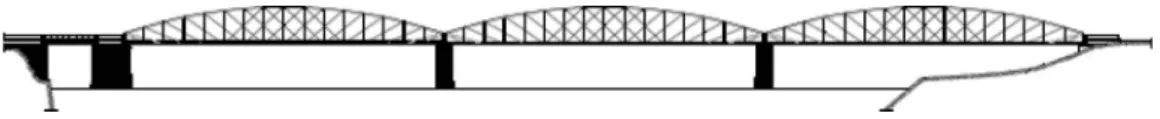
The bridge (see Figure 2) consists of a total of three simply supported spans, with a length of
approxi-mately 69.2 m each, and a short approaching span of approximately 12 m (Pinto et al. 2005). The super-structure of each span is a trough arch steel truss with a semi-parabolic shape and with abutments starting with a height of 2.6 m and reaching about 8.8 m at the mid-span, as is shown in Figure 3. Each span is divided into 16 panels according to the scheme presented in Figure 3. The panels present different lengths: the ones located at the ends have a length between 4.20 and 4.21 m and the others have a length between 4.29 and 4.31 m.
The top chords of the arch trusses are transversally braced (superior bracing), only in the ten middle panels. In the six extreme panels (three at each end), the chord elements are not braced to allow a minimum height for the transit of vehicles. There are two bracing bars between each pair of floor beams, arranged in an X-shape (inferior bracing). The link between the bottom and top chords is accomplished by 17 posts and 22 diagonal elements.
In the transverse direction, the bridge structure has approximately 7 m width, with a concrete slab deck for two traffic lanes. The slab is about 4.60 m width and it has a thickness of 0.18 m. Each span is longitudinally supported on five stringers and on 17 floor beams in the transverse direction. The traffic lanes are bordered by pavements of about 0.70 m width (Pinto et al. 2005).
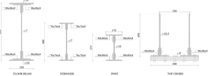
All the structural elements have built-up cross-sections that are generally composed of angles and plates. All the connections are riveted, as it was the common practice at the time. Figure 4 presents cross sections of some truss elements.
Each span end is supported on two simple bearings: on one side roller bearings, allowing free longitudinal displacements and rotations, and at the opposite side, there are two pinned bearings allowing free rotation Figure 1. General view of the Pinha˜o Bridge.
Figure 2. General scheme of the Pinha˜o Bridge structure (approaching span at left and three main spans) (Pinto et al. 2005).
Figure 3. General geometrical characteristics of the Pinha˜o Bridge main spans.
(see Figure 5). Stone masonry abutments and piers constitute the substructure of the bridge.
The yield stress of the steel in the bridge is of 172.5 MPa and the corresponding Young’s modulus is equal to 200 GPa.
2.2. Infiernillo II Bridge
The steel bridge Infiernillo II, built between 2000 and 2003, is located in Mexico (see Figure 6). The bridge crosses the Balsas River and is part of one of the highways that connect the central city of Mexico with the Pacific Coast. Its total length is 525 m, with a deck width of 12.3 m and a total structure width of 15 m. The reinforced concrete piers and abutments are
supported on an infrastructure composed of concrete hollow circular cylinders. Reinforced concrete piles driven up to the hard soil constitute the foundation of the bridge. The superstructure consists of a reinforced concrete deck and trough camel-back-type steel trusses (Jara et al. 2008a).
The bridge has five main spans, each one with a total length of 105 m. The superstructure is composed of two steel arches with a length of 102 m and a maximum height of 16 m (Figure 7). Each span is divided into 17 panels, with a length of approximately 6 m each. Figure 8 shows cross sections of chords and diagonals.
The deck has been made of a light-gauge steel deck cover, with a concrete slab depth of 18 cm. The steel
Figure 4. Cross sections of some elements of the steel arch trusses (adapted from Pinto et al. 2005) (The dimensions presented are in millimeters).
Figure 5. Supports in the Pinha˜o Bridge: (a) roller bearing and (b) pin bearing (Martins et al. 1998).
Figure 6. General view of the Infiernillo II Bridge.
deck serves a double purpose: it provides a framework for the wet concrete, eliminating the necessity for temporary shoring, and provides tensile reinforcement for the hardened slab. The slab is supported on girders, spaced at 1.5 m, which off-load to floor beams with triangular cross sections and spaced at 6 m.
The superstructure is supported on two abutments and four hollow-wall-type concrete piers (8.5 6 3.5 6 15 m3), with a thickness of 0.40 m and 0.60 m in the transverse and longitudinal directions, respec-tively (Figure 9).
The Infiernillo II Bridge is located in the region of the highest level of seismicity in Mexico. It was designed using the load factor design philosophy for the combination of loads recommended by AASHTO standard specifications (1998). The close location of the bridge to the subduction zone led to the use of multi-rotational sliding isolators, positioned at the supports (abutments and columns), as shown in Figure 10.
Isolation systems, aimed at reducing the seismic response of bridges by uncoupling a structure from damaging effects of earthquakes, have been developed. Common isolation devices include frictional/sliding bearings, elastomeric bearings and lead rubber bear-ings. Several of these systems are combined with passive energy devices to control isolator displace-ments. Various experimental studies have shown the
feasibility of the use of metallic yielding devices to enhance the energy dissipation capacity of structures with stable hysteretic behaviour. Reviews of experi-mental and analytical studies are provided in Kelly (1986), Buckle and Mayes (1989), Skinner et al. (1993), Soong and Dargush (1997), Buckle (2000), Soong and Spencer (2002), Jara and Casas (2002), Kunde and Jangid (2003) and Jara et al. (2006b).
2.3. General comparison between the two bridges Tables 1 to 3 present a general comparison between the Pinha˜o Bridge and the Infiernillo II Bridge in terms of construction date, materials and general geometrical characteristics of the superstructure and substructure elements.
In spite of the major span length of the Infiernillo II Bridge (51%), its height/span ratio is only 15% greater Figure 7. General geometrical characteristics of the Infiernillo II Bridge.
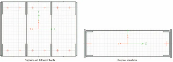
Figure 8. Cross sections of the truss elements.
Figure 9. Cross sections of the hollow-wall-type piers and hollow cylinders.
than the Pinha˜o Bridge ratio. This difference reflects not only the increase in the material strength, but also the knowledge and confidence on the design, analysis and construction methods available at the time of each bridge construction (see Table 2).
Even though the substructure height of the Infiernillo II Bridge and the high seismicity of the site where the bridge is located, the pier slenderness ratio and the pier dimension/span ratio of the Infiernillo II Bridge are smaller than those ratios for the Pinha˜o Bridge. Current design codes demand a minimum seat length and the use of transverse shear keys for avoiding unseating-type failures, as shown in Table 2 for the Infiernillo II bridge. In contrast, the Pinha˜o Bridge, designed with previous codes, lacks transverse shear keys and appropriate seat lengths.
As was typical for a bridge located in a low seismicity area constructed 100 years ago, no trans-verse restrainers (shear keys) were used or a minimum seat length dimension considered.
3. Structural models
3D structural models of the two bridges were devel-oped using the structural analysis software SAP2000 (2006). Numerical analyses of the entire Infiernillo II Bridge and of one simple span were conducted (Jara et al. 2008b). As a result, it can be concluded that the interference between adjacent spans is negligible, due to the wide existing gap between each span preventing deck collision. The same conclusion was assumed for the Pinha˜o Bridge response based on its higher stiffness. Therefore, a structural model, representative of one span, was developed considering the geome-trical and mechanical characteristics for both bridges. Because of the great stiffness of Pinha˜o Bridge’s piers, the superstructure was considered supported on bear-ings fixed at their base (see Figure 11a). In contrast, the great flexibility of the pier-isolation subsystem of the Infiernillo Bridge is of significant importance to its structural response, and therefore the numerical model considered is the one represented in Figure 11b (Jara et al. 2008b). The Infiernillo Bridge numerical model was calibrated based on ambient vibration measure-ments, as is explained in Jara et al. (2008a).
4. Comparative numerical analysis
A comparative analysis was performed to evaluate the structural behaviour and the seismic performance of the Pinha˜o and Infiernillo II Bridges. The bridge models were analysed for vertical and seismic loads. The seismic actions considered in these analyses are in accordance with the Portuguese standard (RSA 1983) and the Mexican code edited by the Comisio´n Federal de Electricidad (CFE 1993).
Natural frequencies, mode shapes, maximum stres-ses in the structural elements and maximum deflection, were determined for both bridges.
4.1. Dead load analysis
4.1.1. Maximum stresses in the structural elements and maximum deflection
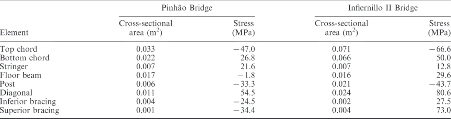
Table 4 presents the maximum stresses in the structural elements of the Pinha˜o and Infiernillo II Table 1. Construction date and materials.
Pinha˜o Bridge Infiernillo II Bridge Construction date 1903 2003 fy(MPa) 172.5 257.9 E(GPa) 200 200
Piers Stone masonry Concrete
f0c¼ 25 MPa fy: steel yield strength, f0c: concrete compressive strength, E: modulus of elasticity.
Table 2. Superstructure elements.
Pinha˜o Bridge
Infiernillo II Bridge
Span length (m) 69.2 105
Bridge width (m) 7 12.3
Truss (height/length ratio) 8.8/69.2¼ 0.13 16/105¼ 0.15
Span dead weight (kN) 3647 12867
Weight/area (kPa) 7.5 9.9
Seat length (m) 0.5 2
Shear keys on bent caps No Yes
Figure 10. Multi-rotational base isolators used in the Infiernillo II Bridge (Aguilar et al. 2006).
Bridges, computed considering only the self-weight of the structures. The elements of the super-structure with higher stress levels for both bridges are the diagonals in tension and top chords in compression.
As shown in Table 5, the maximum stress in the principal structural elements due to dead load is about 32% of the yielding strength for the Pinha˜o Bridge and 31% for the Infiernillo II Bridge, i.e. the dead load effect is practically the same for both structures.
The maximum vertical mid-span deflection esti-mated for the dead load is 36 mm for the Pinha˜o Bridge and 81 mm for the Infiernillo II Bridge. This gives a deflection/span ratio for the Infiernillo II Bridge that is 2.4 times greater than the same ratio for the Pinha˜o Bridge. The more flexible structure of the Infiernillo II Bridge is partially a consequence of design rule evolution in a period of 1 century. It should be noted that the Pinha˜o Bridge was designed using the allowable stress design philosophy and the Infiernillo II Bridge with the load factor design philosophy.
Figure 11. Structural models: (a) Pinha˜o Bridge and (b) Infiernillo II Bridge. Table 4. Maximum stresses in the structural elements.
Pinha˜o Bridge Infiernillo II Bridge
Element Cross-sectional area (m2) Stress (MPa) Cross-sectional area (m2) Stress (MPa) Top chord 0.033 747.0 0.071 766.6 Bottom chord 0.022 26.8 0.066 50.0 Stringer 0.007 21.6 0.007 12.8 Floor beam 0.017 71.8 0.016 29.6 Post 0.006 733.3 0.021 743.7 Diagonal 0.011 54.5 0.024 80.6 Inferior bracing 0.004 724.5 0.002 27.5 Superior bracing 0.001 734.4 0.004 73.0
Table 3. Substructure elements.
Pinha˜o Bridge Infiernillo II Bridge
Bearing type Pin and roller bearings (see Figure 5) Sliding multi-rotational bearings (see Figure 10) Pier geometry (m)
Cylinder geometry (m) –
Rectangular pier height (m) 17.0 20.0
Circular pier height (m) – 25.43–50.13
Total substructure height (m) 17.0 45.43–70.13
Slenderness ratio (H/r) 24.54 30.73
Pier width/span length 3/69.2¼ 0.043 3.5/105¼ 0.033
Pier depth/span length 6/69.2¼ 0.087 8.5/105¼ 0.081
Foundation type Stone masonry foundation; rock Reinforced concrete piles
Soil type (foundation level) Bedrock Bedrock
4.2. Seismic analysis
With the aim of evaluating and comparing the seismic performance of the Pinha˜o and Infiernillo II Bridges, the structural models of both bridges were subjected to various levels of seismic loading. A modal spectral analysis was developed according to the design spectra presented by RSA and CFE codes.
4.2.1. Natural frequencies
The initial analyses were performed by considering the superstructure supported on the bearings fixed at the base, without piers. This idealisation is justified because of the extremely high stiffness of the sub-structure of the Pinha˜o Bridge.
The sliding multi-rotational bearings on the Infiernillo II Bridge show a stable hysteretic and non-degradation behaviour (Mun˜oz 2003). According
to these results, the isolation system exhibited a bi-linear hysteretic behaviour with the elastic stiffness, yield strength, yield displacement and post-yielding strength displayed in Figure 12. The high elastic stiffness exhibited by the device and the small post-yielding stiffness value (about 1% of the elastic stiffness) should be noted. The isolators were modelled as bilinear NLINK elements in SAP2000 considering the Wen model hysteretic behaviour.
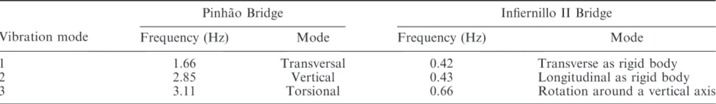
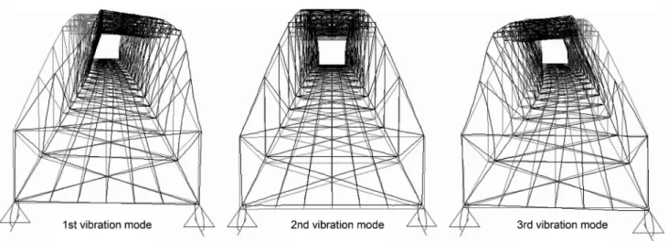
Table 6 presents the first three natural frequencies and mode shapes of the Pinha˜o and Infiernillo II Bridges, computed considering only the self-weight of the structures. The corresponding vibration modes are presented in Figures 13 and 14. As can be seen in Figure 14, the superstructure of the Infiernillo Bridge moves as a rigid body supported on the isolators. If the flexibility of the piers was incorporated into the model, the third mode would correspond to a transverse displacement of the piers with a frequency of 0.68 Hz. The frequencies of the Infiernillo II Bridge shown in Table 6 corresponds to the elastic range of behaviour of the isolation system, hence they are related to the service-limit state of the bridge. For an inelastic response of the isolation system, the post- yielding stiffness of the isolators (1% of their elastic stiffness) slightly reduces the bridge frequencies (about 18%).
As expected, the frequencies obtained for the Pinha˜o Bridge are always higher than the frequencies of the Infiernillo II Bridge. This is due to the differences Table 5. Global response parameters for the dead load.
Pinha˜o Bridge Infiernillo II Bridge Maximum stress on superstructure 0.32fy 0.31fy
Maximum vertical reaction on bearings (MN)
0.9 3.2
Deflection/span ratio 0.0005 0.0012
Figure 12. Hysteretic behaviour model of the isolation system. Table 6. Natural frequencies and mode shapes.
Vibration mode
Pinha˜o Bridge Infiernillo II Bridge
Frequency (Hz) Mode Frequency (Hz) Mode
1 1.66 Transversal 0.42 Transverse as rigid body
2 2.85 Vertical 0.43 Longitudinal as rigid body
3 3.11 Torsional 0.66 Rotation around a vertical axis
between the span length, the height/span ratio and mostly because of the flexibility of the pier-isolators subsystem. For the Infiernillo II Bridge, the mode shapes are governed by the base isolator flexibility.
4.2.2. Seismic zone location of the bridges
The Portuguese code, RSA, divides the Portuguese territory into four zones of seismicity, zones A, B, C and D. Zone A represents the areas of more significant seismicity and zone D represents the areas of reduced seismic risk. In addition, the RSA considers three types of soils: types I, II and III. In the analysis presented in this paper, it is assumed that both bridges are located in zone A, in medium stiffness soil (type II). Additionally, the bridges were subjected to the seismic intensity corresponding to the design spectrum of the CFE (1993), for the highest level of seismicity in Mexico (zone D) and soil type II, where the Infiernillo II Bridge is actually located.
4.2.3. Seismic actions
The RSA establishes two types of seismic actions, one representing earthquakes of moderate magnitude and small focal distance (seismic action type 1) and the other representing earthquakes of higher magnitude and higher focal distance (seismic action type 2). In Figure 15, the design spectra (damping¼ 2%) for the two action types and the acceleration level for the fundamental vibration mode of the bridges are shown. In Figure 16, the CFE design spectra for a 5% damping coefficient is illustrated. In Table 7, spectral accelerations, estimated with both codes and for both structures are presented for the corresponding funda-mental frequencies (f).
The Pinha˜o Bridge is exposed to greater accelera-tions for the three seismic spectra considered as a consequence of its great stiffness. The first mode accelerations for the Infiernillo Bridge are 34%, 45% and 39% of the accelerations for the Pinha˜o Bridge. Figure 13. First three vibration modes of the Pinha˜o Bridge.
Figure 14. First three vibration modes of the Infiernillo II Bridge.
4.2.4. Analysis results
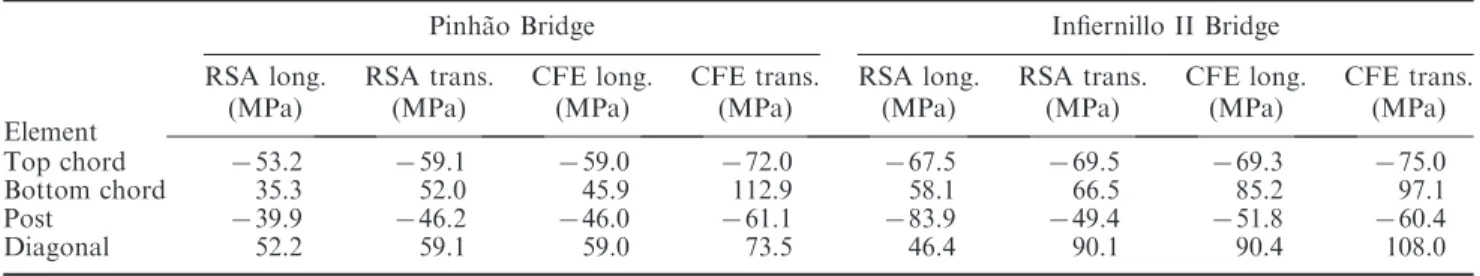
Table 8 presents the maximum stresses in the structural elements of the Pinha˜o and the Infiernillo II Bridges obtained when the bridges are subjected to the design spectrum of the CFE and RSA codes (seismic action type II). In both bridges, the most stressed elements of the superstructure are the bottom chord and the diagonal elements.
The maximum stress due to seismic and dead loads combination is about 65% and 42% of the yield stress for the Pinha˜o and Infiernillo II Bridges, respectively. The maximum stresses produced only by seismic actions are 0.5 fy and 0.18 fy for the Pinha˜o and
Infiernillo II Bridges, respectively.
The transverse deflection obtained at the mid-span section is 16 mm for the Infiernillo Bridge and 18 mm for the Pinha˜o Bridge. The transverse displacement/
Figure 16. Earthquake demand spectrum (CFE 1993).
Table 7. Spectral accelerations for the two bridge structures for the RSA and CFE codes.
RSA CFE Pinha˜o Bridge (f¼ 1.7 Hz) Infiernillo II Bridge (f¼ 0.4 Hz) Pinha˜o Bridge (f¼ 1.7 Hz) Infiernillo II Bridge (f¼ 0.4 Hz)
Type 1 Type 2 Type 1 Type 2 Zone D Zone D
Spectral pseudo-acceleration, a (m s72)
3.2 3.8 1.1 1.7 8.4 3.3
Table 8. Maximum stresses in truss elements due to seismic action and dead load.
Element
Pinha˜o Bridge Infiernillo II Bridge
RSA long. RSA trans. CFE long. CFE trans. RSA long. RSA trans. CFE long. CFE trans.
(MPa) (MPa) (MPa) (MPa) (MPa) (MPa) (MPa) (MPa)
Top chord 753.2 759.1 759.0 772.0 767.5 769.5 769.3 775.0
Bottom chord 35.3 52.0 45.9 112.9 58.1 66.5 85.2 97.1
Post 739.9 746.2 746.0 761.1 783.9 749.4 751.8 760.4
Diagonal 52.2 59.1 59.0 73.5 46.4 90.1 90.4 108.0
Figure 15. Earthquake demand spectrum (RSA 1983) seismic action type: (a) 1 and (b) 2.
span ratio obtained for each bridge is a function of the seismic loading intensity; therefore, the larger value obtained for the Pinha˜o Bridge is justified. Table 9 shows the forces on the piers and the reactions and displacement of the superstructure for dead plus seismic load combination.
5. Global response of the Pinha˜o Bridge supported on base isolators
A numerical analysis was performed aimed at evaluating the influence of the type of bearings on the dynamic behaviour of the Pinha˜o Bridge. An improvement of the bridge response is expected if bearing isolators of the type used in the Infiernillo II Bridge are incorporated. The period increase would result in a reduced acceleration demand, as can be observed in Figure 15. The isolator’s properties are selected in such a way that the fundamental period of the bridge is increased three times, from 0.6 to 1.8 s. To drive the period of the bridge to 1.8 s, the lateral stiffness of the supports, considered to be the equivalent stiffness associated with the maximum expected displacement of the isolator, should be 2511 kN/mm. The supports were modelled in SAP2000 as link elements with bilinear behaviour.
The model was subjected to seismic loading (type II) and computed according to the RSA design spectra, with the following characteristics: zone A, soil type II, 2% damping coefficient, and to the CFE design spectra for zone D and the same type of soil.
The dynamic behaviour of the Pinha˜o Bridge, with and without base isolators, is commented on in the following paragraphs.
5.1. Natural frequencies
Table 10 presents the first three vibration modes of the isolated Pinha˜o superstructure. The fundamental fre-quency of the bridge was reduced from 1.66 Hz for the non-isolated structure to 0.94 Hz for the isolated structure. This period shift reduces the spectral accel-eration from 3.8 m s72to 2.0 m s72in the case of the RSA spectra and from 8.4 m s72 to 5.8 m s72in the CFE spectra.
5.2. Analysis results
The flexibility of the isolation system modifies the mode shapes of the non-isolated model. The vibration modes are now similar to those of the Infiernillo II Bridge previously commented. Unlike the dynamic properties of the non-isolated model, the frequency values of the first and second modes (corresponding to transverse and longitudinal directions) are quite similar for the isolated bridge, mainly due to the same stiffness of the isolation system in both directions.
Table 11 shows the maximum stress values in the structural elements for the Pinha˜o Bridge supported on base isolators when it is subjected to the seismic action defined by the response spectra. It is notorious that the stresses due to seismic actions are smaller than the stresses caused by the dead load (Table 4).
Table 9. Analysis results (seismic load plus self weight condition).
Pinha˜o Bridge
Infiernillo II Bridge
RSA CFE RSA CFE
Reaction on piers (kN) 1167 1461 4469 4464 Longitudinal shear on piers (kN) 376 842 570 1720 Transverse shear on piers (kN) 1200 2724 1754 1761 Longitudinal displacement (cm) 0.82 0.97 11.2 38.8 Transverse displacement/span 0.0003 0.0007 0.0012 0.0039 Transverse relative displacement/span 0.0003 0.0007 0.0002 0.0005
Table 10. Numerical natural frequencies and corresponding vibration modes of the Pinha˜o Bridge supported on base isolators.
Vibration mode
Frequency
(Hz) Mode
1 0.94 Transverse displacement as rigid
body
2 1.01 Longitudinal displacement as rigid
body
3 1.70 Rotation around a vertical axis
Table 11. Maximum stress (MPa) in the structural elements of the Pinha˜o Bridge considering the use of base isolators.
Element Pinha˜o Bridge RSA long RSA trans CFE long CFE trans Top chord 745.5 746.6 746.7 750.8 Bottom chord 14.7 19.1 19.4 34.4 Post 736.4 736.9 740.6 742.4 Diagonal 57.9 59.2 61.5 66.0
Regarding the maximum stress in the structural elements, the use of base isolators produces the stress ratios presented in Table 12. In general, the use of base isolators led to a reduction of the maximum stresses. The structural elements most sensitive to the change of bearings conditions are the bottom chords. This is probably due to the higher restriction of the bridge’s displacements imposed by the original bear-ings. When the Pinha˜o Bridge is isolated, a stress reduction of up to 43% was obtained. The stress decrease is greater in transverse direction, while in the longitudinal direction, the maximum reduction is 24%. The CFE/RSA spectral acceleration ratio corresponding to the non-isolated bridge is 1.32, while this ratio is reduced to 1.15 for the isolated bridge, showing the minor influence of the seismic action when the isolators are incorporated into the bridge.
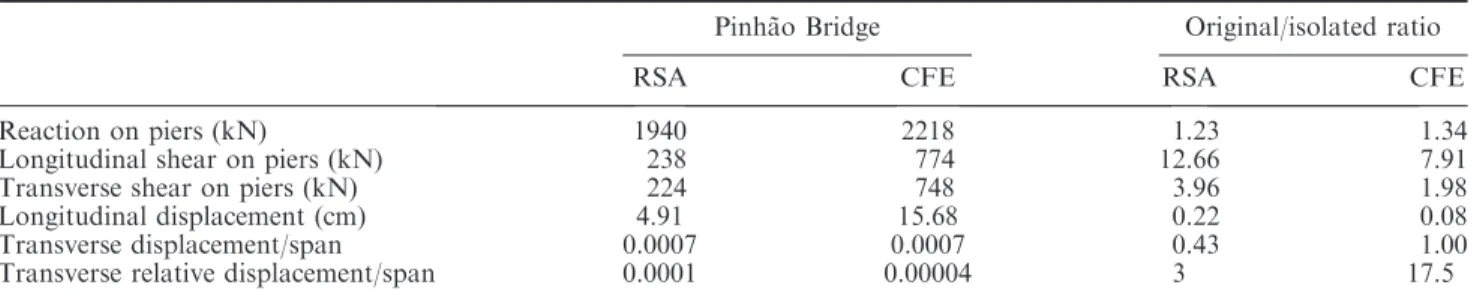
Table 13 shows the forces on the piers and the reactions and displacement of the isolated super-structure for the dead plus seismic load combination. The response ratio of the original structure versus the isolated one is also shown. The large ratio obtained for longitudinal shear on the piers, mainly due to the longitudinal movement restriction of bearings in the original model, is remarkable. It is also important to note that the transverse relative displacement/span ratios of the Pinha˜o Bridge are quite similar to those obtained in the isolated Infiernillo II Bridge model, despite the differences in length of both bridges.
6. Conclusions
Two bridges, built in different periods with similar geometrical characteristics and almost the same stress levels under dead loads, have been analysed from the point of view of their seismic response. The following conclusions can be drawn:
. As a result of the comparative study, it is possible to affirm that the truss structural system of both bridges is very similar. The use of a light-gauge steel deck is the main difference in both super-structures. The vertical behaviour of the bridges is also quite similar, showing the main difference related to their seismic performance, the lack of seismic details and the massive substructure used in the Pinha˜o Bridge.
. In spite of the major span length and width of the Infiernillo Bridge, the height/span ratio is 46% of the Pinha˜o Bridge ratio. This difference reveals, not only the increase on the material strength, but also the confidence of the design, analysis and construction methods available at the time the bridges were constructed.
. The same conclusion can be drawn regarding the pier slenderness ratio and the pier dimension/ span ratio, despite the taller piers of the Infiernillo II Bridge and the high seismicity of the site where the Infiernillo II Bridge is located. As was usual for a bridge located in a low seismicity area constructed 100 years ago, no transverse restrai-ners (shear keys) were used, nor was a minimum seat length dimension considered.
. The frequencies of the Pinha˜o Bridge are always higher than the frequencies of the Infiernillo II Bridge as a result of the differences between the span length, the height/span ratio and mostly because of the flexibility of the pier-isolators subsystem.
. Seismic stress demands in the Pinha˜o Bridge are larger than those of the Infiernillo II Bridge for the three spectra considered, exposing the difference in dynamic properties in both bridges. Table 12. Ratio of maximum stress with and without
isolators. Element Pinha˜o Bridge RSA long. RSA trans. CFE long. CFE trans. Top chord 1.24 1.15 1.24 1.43 Bottom chord 2.40 2.72 2.37 3.28 Post 1.24 1.08 1.13 1.42 Diagonal 1.19 1.09 1.12 1.35
Table 13. Isolated Pinha˜o model (seismic load plus self-weight condition).
Pinha˜o Bridge Original/isolated ratio
RSA CFE RSA CFE
Reaction on piers (kN) 1940 2218 1.23 1.34
Longitudinal shear on piers (kN) 238 774 12.66 7.91
Transverse shear on piers (kN) 224 748 3.96 1.98
Longitudinal displacement (cm) 4.91 15.68 0.22 0.08
Transverse displacement/span 0.0007 0.0007 0.43 1.00
Transverse relative displacement/span 0.0001 0.00004 3 17.5
Even though there were similar stresses in both bridges caused by the dead load, the maximum stresses produced by seismic actions are more than 2.7 times for the Pinha˜o Bridge.
. An important stress reduction is obtained when the Pinha˜o Bridge is isolated. The stress decrease is greater in the transverse direction. The CFE/ RSA spectral acceleration ratio corresponding to the non-isolated Pinha˜o Bridge is 1.32, while this ratio is reduced to 1.15 for the isolated bridge, showing the minor influence of the seismic action when the isolators are incorporated into the bridge.
. The comparative analysis, in terms of seismic performance of the two bridges, confirmed that the incorporation of base isolators resulted in a significant reduction of seismic vulnerability and in the improvement of global structural beha-viour of the Pinha˜o Bridge. Similar results can be expected in other bridges if this retrofitting technique is adopted.
Acknowledgements
The authors would like to acknowledge the GEG – Gabinete de Estruturas e Geotecnia Lda (Portugal), the OPWAY Engenharia, S.A. and the EP – Estradas de Portugal S.A. (Portugal), particularly Eng. Anto´nio Campos e Matos, Eng. Alberto Goncalves and Eng. Eduardo Andrade Gomes, respectively, for the data related to the Pinha˜o Bridge, inspections, assessment, geometry and material characterisa-tion results.
References
Aguilar, I., 2006. Comportamiento dina´mico de un puente con aisladores de base histere´ticos. Master Thesis, UMSNH, Mexico (in Spanish).
American Association of State Highway and Transportation Officials (AASHTO), 1998. LRFD bridge design specifi-cations. 2nd ed. Washington, DC: AASHTO.
Astaneh-Asl, H., Bolt, B., Mc Mullin, K., and Cho, S., 1994. Seismic performance of steel bridges during the Northridge Earthquake. Department of Civil Engineering, University of California at Berkeley, UCB/CE-Steel-94/0.
Buckle, I.G., 2000. Passive control of structures for seismic loads. In: Proceedings of the 12th world conference on earthquake engineering, Auckland, New Zealand. paper 2825.
Buckle, I.G. and Mayes, R.L., 1989. The application of seismic isolation to bridges. In: Structures congress 089, seismic engineering: research and practice. New York, NY: ASCE, 633–642.
Comisio´n Federal de Electricidad (CFE), 1993. Manual de disen˜o de obras civiles de la comisio´n federal de electricidad, disen˜o por sismo. Instituto de Investigaciones Ele´ctricas de la CFE (in Spanish).
Eshghi, S. and Ahari, M.N., 2005. Performance of transpor-tation systems in the 2003 Bam, Iran, Earthquake. Earthquake Spectra, 21 (S1), S455–S468.
Faria, R.G., 2008. Procedimentos com vista a` monitorizac¸a˜o de estruturas – teste do sonar e ensaio da Ponte do Pinha˜o. Thesis (Masters). Faculty of Engineering, University of Porto, Porto, Portugal (in Portuguese).
Hashimoto, S., Fujino, Y., and Abe, M., 2005. Damage analysis of Hanshin Expressway Viaducts during 1995 Kobe Earthquake. II: damage mode of single reinforced concrete piers. Journal of Bridge Engineering, 10 (1), 54– 60.
Hsu, Y.T. and Fu, C.C., 2004. Seismic effect on highway bridges in Chi Chi earthquake. Journal of Performance of Constructed Facilities, 18 (1), 47–53.
Jara, M. and Casas, J.R., 2002. Criteria for the design of isolated bridges, Monografı´a CIMNE IS-49. Centro Internacional de Me´todos Nume´ricos en Ingenierı´a, Barcelona, Espan˜a (in Spanish).
Jara, M., A´lvarez, J.J., and Jara, J.M., 2006a. Algunas deficiencias de puentes sı´smicamente vulnerables. In: Memorias del XV Congreso Nacional de Ingenierı´a Estructural, Puerto Vallarta, Jalisco (in Spanish). Jara, M., Jara, J.M., and Casas, J.R., 2006b. Seismic
protection of structures with control devices, Morelia, Michoacan. Mexico: Fondo Editorial Morevallado (in Spanish).
Jara, J.M., Jara, M., and Herna´ndez, H., 2008a. Expected behavior of the Infiernillo II Bridge in Mexico. In: Sixth national conference on bridges and highways, Charleston, South Caroline, USA, paper ID 3A1-3.
Jara, J.M., Galva´n, A., Aguilar, I., Jara, M., and Herna´ndez, H., 2008b. Seismic vulnerability of an isolated bridge in Mexico. In: 14th world conference on earthquake engineering, Beijing, China, paper ID 05-02-0109.
Jesus, A.M.P., Figueiredo, M.A.V., Ribeiro, A.S., Castro, P.M.S.T., and Fernandes, A.A., 2009. Residual Lifetine Assessment of an Ancient Riveted Steel Road Bridge. Strain, 14. doi: 10.1111/j.1475-1305.2008.00596.x. Kawashima, K., 2002. Damage of bridges resulting from
fault rupture in the 1999 Kocaeli and Dunce, Turkey earthquakes and the 1999 Chi-Chi, Taiwan earthquake. Structural Engineering/Earthquake Engineering, 19 (2), 179s–197s.
Kelly, J.M., 1986. Seismic base isolation: a review and bibliography. Soil Dynamics and Earthquake Engineering, 5, 202–216.
Kunde, M.C. and Jangid, R.S., 2003. Seismic behavior of isolated bridges: a state-of-the art review. Electronic Journal of Structural Engineering, 3, 140–164.
Martins, M., Torres, M., and Freire, P., 1998. Pontes Rodovia´rias Meta´licas. Junta Auto´noma de Estradas, Portugal, ISBN 972-8498-03-9 (in Portuguese).
Moehle, J.P. and Eberhard, M.O., 2003. Earthquake damage to bridges. In: W.-F. Chen and L. Duan, eds. Bridge Engineering. Seismic Design. CRC Press, pp. 2-1-2-33.
Mun˜oz, D., 2003. A bridge seismic behavior supported on multirotational isolation system. Master Thesis, UNAM, Mexico (in Spanish).
Pinto, J., Santos, N., and Fonseca, R., 2005. Ponte meta´lica do Pinha˜o – inspecc¸a˜o e elaborac¸a˜o do estudo de reabilitac¸a˜o da obra de arte. Porto, Portugal (in Portuguese).
RSA, 1983. Regulamento de Seguranc¸a e acc¸o˜es para estruturas de edifı´cios e pontes, Decreto-Lei no 235/83, de 31 de Maio. Porto, Portugal: Porto Editora (in Portuguese).
SAP2000, 2006. Linear and nonlinear static and dynamic analysis and design of three-dimensional structures, Ver-sion 11. Computer and Structures, Inc.
Skinner, R.I., Robinson, W.H., and McVerry, G.H., 1993. An introduction to seismic isolation. Chichester, UK: John Wiley & Sons.
Soong, T.T. and Dargush, G.F., 1997. Passive energy dissipation systems in structural engineering. Chichester, UK: John Wiley & Sons.
Soong, T.T. and Spencer, B.F., 2002. Supplemental energy dissipation: state-of-the-art and state-of-the-practice. Engineering Structures, 24 (3), 243–259.
Uang, C., Elgmanal, A., Li, W., and Chou, C., 1999. Ji-Ji, Taiwan earthquake of September 21, 1999: a brief reconnaissance report. Department of Structural Engi-neering, University of California, San Diego. Available online from: http://www.structures.ucsd.edu/taiwaneq/ taiwan1.htm