ASHBY METHOD IN THE SELECTION OF MATERIALS FOR THE BRAKE DISC AND AXIS OF TRANSMISSION OF A PROTOTYPE BAJA SAE
André Rabelo Moraes1 Dayane Cussiol Monfardim1 Igor Loureiro Coura1 Joana Freitas Campana1 Lazaro Ernesto Ferreira1 Mario Augusto Alves de Deus Filho1 Renato Fontana Souza1 Antonio Carlos Barbosa Zancanella1*
Rômulo Maziero2 Bruno Dorneles de Castro2
ABSTRACT
The objective of this work was to analyze the selection of materials for two components of a Baja SAE prototype, specifically the brake disc and the vehicle transmission axis, in order to choose materials that would meet the design requirements. The indices of merit, mechanical strength, thermal fatigue and thermal properties were considered using the Ashby method in the choice of materials. The results indicated that the best material for the brake disc was the steel alloys and for the transmission shaft tungsten, aluminum nitride, steel alloys and carbon fiber reinforced polymer.
KEYWORDS: Materials; Brake disc; Drive shaft; Ashby method.1
1 INTRODUCTION
11Federal Institute of Education, Science and Technology of Espirito Santo (IFES), Espirito Santo, ES, Brazil. [email protected]
2Post-Graduate Program in Mechanical Engineering (PPGMEC), Federal University of Minas Gerais (UFMG), Minas Gerais, MG, Brazil
The Baja SAE project is a challenge to engineering students by the Society of Automotive Engineers, where they engage with a real-world case for project development, from conception, designing, and building an off-road vehicle. In Brazil, it is called the Baja SAE BRASIL project.
The SamaBaja team represents the Federal Institute of Education, Science and Technology of Espirito Santo (Sao Mateus, Brazil), and its purpose is to build an off-road vehicle in the city. All the technical knowledge to build the vehicle comes from the students involved in the project, putting into practice what was learned in the room. In addition, the staff is led by some teachers, especially in management.
To structure the development of the mini Baja prototype, a logical sequence of phases was adopted. The activities were then divided into four stages: Planning and Management, which explains the organization and the way the team works; Detailed design, which technically describes the design and dimensioning of the vehicle; Production, points out the methods used to manufacture the components and; Tests, which presents the real performance of the prototype in dynamic demonstrations, in front of everything that was produced.
The project is divided by sectors: chassis, suspension and steering, brakes, sensing and transmission. From the experience and problems acquired in previous competitions, there was a demand in the study and selection of the best material for components in the brake and transmission sectors.
In motor racing competitions, such as the project Baja SAE BRASIL, the braking power and durability of the brake system components are very important for vehicle performance. According to Lim and Goo (2015), this is important point to consider when choosing a material to make a brake disc, since small losses of performance in this system can cost positions in the final classification of the competition.
Brake discs can be made of metals, such as cast iron, alloy steel, or also ceramic (Stadler et al., 2007) and composite materials (Gultekin et al., 2010). The choice of the best material for brake disc construction should take into account factors such as weight, heat dissipation, cost, fatigue strength, among others (Augustins et al., 2017). Machine designs are often seen as the task of designing shafts, to which are coupled other mechanical elements, such as gears, pulleys, centered wheels, among others. It is common that along the axis there are tear and keyways for fixing the components.
In this context, the objective of this work was to analyze the selection of materials of two components for the prototype mini Baja SAE, due to the problems that the SamaBaja team faced in the previous competitions as, for example, the brake system failure during the braking test and the fracture of the transmission axis along the endurance test.
2 METHODS AND MATERIALS
2.1 ANALYSIS OF MERIT INDEX RELATED TO THE BRAKE
For the brake disc, the design criteria to be analyzed and which directly influence brake performance are low density, high stiffness (high modulus of elasticity), wear resistance, high thermal conductivity and thermal diffusibility, low coefficient of expansion thermal and cost.
Wu et al. (2019) mention that the material of the brake disc must be able to withstand the high thermal stress caused during the thermal cycles in the course of the use and also the thermal energy constituted must be dissipated as soon as possible.
2.1.1. Mechanical strength of brake disc
Brake discs must have thermal and mechanical strength, to support the stress applied in applications. For this, it is necessary to understand exactly what are and where the forces present. So, applying the equilibrium equations, has, on the x axis:
∑ 𝐹𝑥 = 𝐹𝑟𝑒𝑠𝑢𝑙𝑡𝑖𝑛𝑔 ∑ 𝐹𝑥 = 𝐹𝑎𝑥𝑖𝑎𝑙 − 2𝐹𝑟𝑜𝑡𝑜𝑟− 𝐹𝑡𝑖𝑟𝑒 On the y axis: ∑ 𝐹𝑦 = 0 𝑁 = 𝑊 To the moments:
∑ 𝑀0 = (2𝐹𝑟𝑜𝑡𝑜𝑟×𝐷𝑟𝑜𝑡𝑜𝑟 2 ) − (𝐹𝑡𝑖𝑟𝑒 × 𝐷𝑡𝑖𝑟𝑒 2 ) = 𝐼 × 𝑎 In deceleration: 𝑉 = 𝑉0+ 𝑎𝑥× 𝑡 As V = 0, total stop: 𝑎𝑥 = −𝑉0 𝑡𝑠
The speed V (m/s) of the car corresponds to W (rad/s) of the rotor, which is equal to the speed of rotation of the tire:
2 ( 𝑉 𝐷𝑡𝑖𝑟𝑒) = 𝑊 = 2 ( 𝑉𝑟𝑜𝑡𝑜𝑟 𝐷𝑟𝑜𝑡𝑜𝑟) 𝑉𝑟𝑜𝑡𝑜𝑟(𝑡) = ( 𝐷𝑟𝑜𝑡𝑜𝑟 𝐷𝑡𝑖𝑟𝑒 ) × (𝑉0− 𝑉0 𝑡𝑠 × 𝑡)
It is considered that the analyzed wheel receives C% of the braking load, thus by the energy approach: 𝐸𝑐(𝑐𝑎𝑟) = 𝑃𝑜𝑡(𝑟𝑜𝑡𝑜𝑟 𝑑𝑖𝑠𝑠𝑖𝑝𝑎𝑡𝑒𝑑) 𝐶 ×1 2× 𝑀 × 𝑉0 2 = ∫ 2 × 𝐹 𝑟𝑜𝑡𝑜𝑟 × 𝑉𝑟𝑜𝑡𝑜𝑟 𝑑𝑡 𝑡𝑠 0 𝐶 ×1 2× 𝑀 × 𝑉0 2 = 2 × 𝐹 𝑟𝑜𝑡𝑜𝑟 × 𝐷𝑟𝑜𝑡𝑜𝑟 𝐷𝑡𝑖𝑟𝑒 × (𝑉0 × 𝑡𝑠− 𝑉0 𝑡𝑠 × 1 2 × 𝑡𝑠 2) Therefore: 𝐹𝑟𝑜𝑡𝑜𝑟 = 𝐶 × 𝑀 × 𝑉0 2 × 𝐷 𝑡𝑖𝑟𝑒 𝐷𝑟𝑜𝑡𝑜𝑟 × 𝑉0 × 𝑡𝑠
The function is to dissipate kinetic energy from the car during braking, in addition to minimizing mass and braking time and maximizing the critical size of the cracks. The constants are the rotor and tire geometry, vehicle speed, vehicle mass and braking load distribution. Therefore, the following equations are applied:
𝑡𝑠 = 𝐶 × 𝑀 × 𝑉02× 𝐷𝑡𝑖𝑟𝑒 𝐷𝑟𝑜𝑡𝑜𝑟× 𝑉0× 𝐹𝑟𝑜𝑡𝑜𝑟 𝐸𝑞. 01 𝐹𝑟𝑜𝑡𝑜𝑟 = 𝜎𝑒 𝐴𝑝𝑎𝑑 𝐸𝑞. 02 𝑚𝑚𝑜𝑡𝑜𝑟 = 𝜌 × 𝜋 × 𝐷𝑟𝑜𝑡𝑜𝑟 2 4 × 𝑒 𝐸𝑞. 03 𝑎𝑐 = (𝐾𝐼𝐶 𝜎𝑒) 2 ×1 𝜋 𝐸𝑞. 04 Where e is the disc thickness.
Substituting Equations 02, 03 and 04 in Equation 01:
𝑡𝑠× √𝑚𝑟𝑜𝑡𝑜𝑟 𝑎𝑐 = 𝐶 × 𝑀 × 𝑉02× 𝐷𝑡𝑖𝑟𝑒 𝑉0× 1 𝐴𝑝𝑎𝑠𝑡𝑖𝑙𝑙𝑒× √𝜋× √ 4 𝜋 × 𝑒 × (√𝜌 𝐾𝐼𝐶)
Therefore, for the index of merit:
𝐼𝑀 = 𝐾𝐼𝐶
2
𝜌
2.1.2. Thermal fatigue
Regarding to thermal fatigue, if the rotor could freely expand:
∆𝑏′= 𝛼 × 𝑏 × ∆𝑇
From the theory of elasticity and considering a situation of EPD (flat state of deformations), it is observed that for a vessel with only internal pressure (rotor):
∆𝑏 = 𝑃
𝐸× 𝑏 × [(
𝑎2+ 𝑏2
𝑎2− 𝑏2) − 𝑣]
Considering also, for a vessel with internal radius equal to zero (cube) and only with external pressure:
∆𝑐 =𝑃
𝐸× 𝑐 × (1 − 𝑣)
Thus, the sum of these deformations must be equal to the free deformation of the rotor.
∆𝑏′= ∆𝑏 + ∆𝑐 Substituting equations: 𝑃 = 𝛼 × ∆𝑇 × 𝐸 [(𝑎2+ 𝑏2 𝑎2− 𝑏2) + 1] ∆𝑇 = [(𝑎 2 + 𝑏2 𝑎2 − 𝑏2) + 1] × 𝑃 𝛼 × 𝐸
For Pmax = σe/Acontact, it has:
∆𝑇 = [(𝑎2+ 𝑏2 𝑎2− 𝑏2) + 1] 𝐴𝑐𝑜𝑛𝑡𝑎𝑐𝑡 × ( 𝛼𝑒 𝛼 × 𝐸)
For the index of merit related to thermal fatigue, that the function is to dissipate the kinetic energy of the car in the braking and to minimize the temperature variation. For this, the constants of disk thickness and the properties of the materials, results in the following index of merit:
𝐼𝑀 = 𝜎𝑒 𝛼𝐸
3.1 ANALYSIS OF MERIT INDEX RELATED TO THE AXIS
For the selection of the material of the drive shaft, it is necessary to find the following material properties: low density; high stiffness; mechanical strength; bending; cost and benefit ratio.
Therefore, for the choice of materials, it is necessary to perform the analysis of these characteristics in an axis, through the index of merit (IM), thus obtaining, a more precise selection of the material before the map of Ashby. In the first case, consider a circular bar (axis) of size L and radius r, undergoing flexion deflection by force F. Starting from known equations:
𝜑 = F × 𝐿 3 48 × 𝐸 × 𝐼 𝐸𝑞. 05 I =π × 𝑟 4 4 = 𝐴2 4 × π 𝐸𝑞. 06 A = m 𝐿 × ρ 𝐸𝑞. 07
Substituting Equation 06 into Equation 07, it has:
𝜑 = 𝐹 × 𝐿
3× π
12 × E × 𝐴2 𝐸𝑞. 08
Thus, when replacing Equation 07 in Equation 08, it finds:
𝑚2 = 𝐹 × 𝐿 5× ρ2× π 12 × E × 𝜑 𝑚 = √𝐹 × 𝐿 3 12 × 𝜑[ ρ 𝐸12 ]
In order to optimize the index of merit and to reduce the mass so that there is a smaller deflection of the beam, one has:
𝐼𝑀 =𝐸
1 2
ρ
For the second case, it is known that the shaft must withstand a torque without fracture. Therefore, a property that must be analyzed is the rigidity of the material, therefore, considering torsion, the following index of merit:
IM =G ρ
Where G is the transverse modulus of elasticity, which is 3/8 of Young's modulus (E).
3.2 ANALYSIS OF ASHBY MAPS TO THE BRAKE DISC
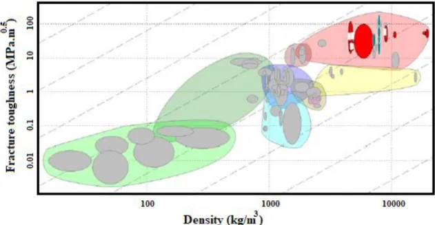
The CES EduPack 2013 software was used to analyze the Ashby maps. The limits of the analyzed properties - modulus of fracture toughness x density, are presented in Table 1 and Figure 1.
Table 1 - Properties limit: modulus of toughness
Properties Minimum Maximum
Modulus of toughness (MPa.m½)
36 58
Figure 1: Ashby map: modulus of fracture toughness x density Source: Authors, 2019.
The materials selected by the Ashby map analysis were: cast iron; copper alloys; gold; alloy steel; silver; titanium alloys; zinc alloys and tungsten alloys. The limits of the properties analyzed – yield strength x thermal expansion coefficient, are shown in Table 2 and Figure 2.
Table 2 - Properties limit: yield strength x thermal expansion coefficient
Properties Minimum Maximum
Yield strength (MPa) 3,3 -
Thermal expansion coefficient (µstrain/ºC) 10 29
Figure 2: Ashby map: yield strength x thermal expansion coefficient. Source: Authors, 2019
The following materials were selected with the aid of the Ashby map: aluminum alloys; cast iron; fiberglass reinforced polymer and steel alloys.
The initial idea was to analyze the thermal diffusibility in relation to thermal conductivity, however, the relationship between the two properties is very similar for all materials. Therefore, it is not possible to obtain an accuracy in the choice of material through these two properties. The limits of the analyzed properties - thermal expansion coefficient x thermal conductivity, are presented in Table 3 and Figure 3.
Table 3 - Properties limit: termal expansion coefficient x thermal conductivity
Properties Minimum Maximum
Thermal conductivity (W/m.ºC) 35 55 Thermal expansion coefficient (µstrain/ºC) 10 29 Source: Authors, 2019
Figure 3: Ashby map: thermal expansion coefficient x thermal conductivity. Source: Authors, 2019 The materials selected by these properties were: ductile iron, ductile and gray; alloy steel; magnesium alloys and lead alloys.
3.3 ANALYSIS OF THE ASHBY MAPS FOR THE DRIVE SHAFT
For this study, it is necessary that the shaft has, at the same time, mechanical characteristics such as ductility in its core and high resistance to abrasion, represented by the high hardness, in the superficial part. In addition, a low cost material and high fatigue strength is required.
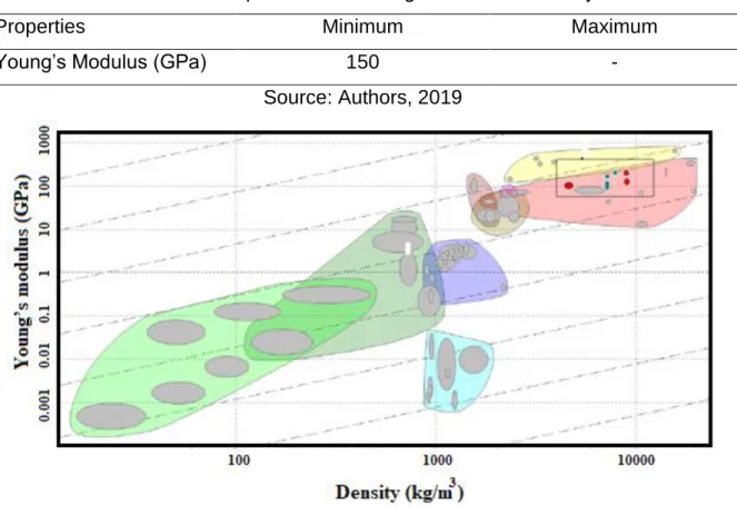
To achieve the objectives mentioned in the paragraph above, the best combination to be chosen is to use steel with some type of heat treatment. Among the most commonly used steels are carbon steels such as SAE 1020, 1040, 1050 and alloy steels 3145, 3150, 4320, 4340, 8620 and 8640. The limits of the analyzed properties – Young’s modulus x density, are presented in Table 4 and Figure 4.
Table 4 - Properties limit: Young’s modulus x density
Properties Minimum Maximum
Young’s Modulus (GPa) 150 -
Source: Authors, 2019
Figure 4: Ashby map: Young’s modulus x density. Source: Authors, 2019
The materials selected by these properties were: cast iron; copper alloys; alloy steel; nickel alloy; stainless steel and titanium alloy.
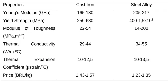
The criteria of the selection of the best material were determined by the combinations of properties such as Young’s modulus, density, thermal expansion coefficient, thermal conductivity and fracture toughness modulus (Table 5).
Table 5 - Cast Iron and Steel Alloy: properties
Properties Cast Iron Steel Alloy
Young’s Modulus (GPa) 165-180 205-217
Yield Strength (MPa) 250-680 400-1,5x10³
Modulus of Toughness (MPa.m1/2) 22-54 14-200 Thermal Conductivity (W/m.ºC) 29-44 34-55 Thermal Expansion Coefficient (µstrain/ºC) 10-12,5 10-13,5 Price (BRL/kg) 1,43-1,57 1,23-1,35 Source: Authors, 2019
In the selection of the disk, analyzing the three maps of Ashby, it is possible to observe that the two materials that serve all the maps are the cast iron and the alloys of steel. Comparing the two materials, the steel alloys have higher thermal conductivity, higher fracture toughness, higher flow resistance and the same coefficient of thermal expansion, as shown in Table 5.
Besides the better mechanical and thermal properties, there is also an advantage of the steel in relation to the ductile iron as to the machinability. Steel, compared to cast iron, is easier to be machined, since cast iron is more brittle, which makes it difficult to work on the material, especially in heat dissipation holes. Therefore, considering all these factors, it is observed that the best material for the brake disc is steel alloys.
4 CONCLUSION
In this study, Ashby method was used to choose the best material for the brake disc and the vehicle transmission axis of a Baja SAE prototype.
For the selection of the transmission axis, from the analysis of the maps of Ashby, it is observed that the materials that meet the low density and / or high Young’s modulus
are: tungsten alloys, aluminum nitride, alloys of steel and carbon fiber reinforced polymer (CFRP).
From the analysis of the Young’s modulus, it is verified that the best materials would be the alloys of tungsten, aluminum nitride and alloys of steel. However, tungsten alloys have high density and are expensive. Aluminum nitride has excellent properties, but it is the most expensive material, according to the price stipulated by the software, so it was discarded. Alloys of steel are interesting, having a Young’s modulus smaller than tungsten alloys, with a lower density. Already compared to aluminum nitride, the alloys of steel have a larger Young’s modulus, but with a higher density. However, steel alloys are much cheaper than the other two materials, and have good mechanical properties.
Lastly, considering the economic factor and the mechanical properties, it was concluded that the steel alloys are the best materials for the brake disc and the transmission shaft of the mini Baja prototype.
5 ACKNOWLEDGEMENTS
The authors would thank to the Federal Institute of Education, Science and Technology of Espírito Santo - IFES and to the Post-Graduate Program in Mechanical Engineering - PPGMEC of the Federal University of Minas Gerais - UFMG by the physical structure and support. The authors would thank to the Brazilian Agencies CAPES, CNPq and FAPEMIG for financial support.
6 REFERENCES
AUGUSTINS, L., HILD, F., BILLARDON, R., BOUDEVIN, S. Experimental and numerical analysis of thermal striping in automotive brake discs. Fatigue & Fracture
of Engineering Materials & Structure, v. 40, p. 267-276, 2017.
GULTEKIN, D., UYSAL, M., ALAF, A. M. GULER, M. O. AKBULUT, H. The effects of applied load on the coefficient of friction in Cu-MMC brake pad/Al-SiCp MMC brake disc system. Wear, v. 270, p. 73-82, 2010.
LIM, C-H., GOO, B-C. Development of Compacted Vermicular Graphite Cast Iron for Railway Brake Discs. Metals and Materials International, v. 17, n. 2, p. 199-205, 2011.
STADLER, Z., KRNEL, K., KOSMAC, T. Friction behavior of sintered metallic brake padson a C/C–SiC composite brake disc. Journal of the European Ceramic
WU, Y., LIU, W., CHEN, H., CHEN, Y. LI, H. YI, W. Microstructure evolution and crack propagation feature in thermal fatigue of laser-deposited Stellite 6 coating for brake discs. Surface & Coatings Technology, v. 358, p. 98-107, 2019.