Nanolubrication
J.L. Mansot, Y. Bercion, L. Romana
Groupe de Technologie des Surfaces et Interfaces (GTSI EA 2432), Universit´e des Antilles et de la Guyane, UFR Science Exactes et Naturelles Pointe a Pitre C´edex Guadeloupe (FRANCE)
J.M. Martin
Laboratoire de Tribologie et Dynamique des Systemes (LTDS UMR 5513), Ecole Centrale de Lyon, 36 avenue Guy de Collongue, 69134 Ecully c´edex (FRANCE)
(Received on 1 July, 2008)
Lubrication strategies developed long time ago employed amphiphilic molecular lubricant additives to confer to lubricating oils or greases specific properties such as friction reduction, antiwear, anticorrosion. The under-standing of their action and the development of various type of nanoparticles are at the origin of new lubrication strategies using composite or functionalized nanoparticles in dispersion in lubricating oils or greases to confer to the lubricants the needed functions. The present work is concerned with the presentation of these new ap-proaches. Some examples will be developed to show the main aspects of the mechanisms of action of these new nano-additives.
Keywords: tribology, colloidal additives, reverse micelles, nanoparticles
I. INTRODUCTION
Tribology has been introduced in early humanity ages [1] as far as, during stone age, contact mechanics is involved in the cutting and polishing of flints and friction between two flints or two wood peaces is used for fire ignition. An Egyp-tian bas - relief, found in the Tehuti-Hetep’s grave (1880 BC), is probably one of the first documents reporting the use of lu-bricant (water or oil) to reduce friction between the sleigh, used for a 60 tons statue transportation, and the boards on which it slides.
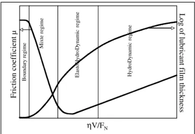
The two basic laws of friction, expressing that friction re-sistance is proportional to normal load and independent on the contact area between solids, seem to be first mentioned by Leonardo da Vinci (1452-1519) and rediscovered by Guil-laume Amontons in 1699 [2]. These observations were veri-fied, in 1785, by Charles Augustin Coulomb [3]. He did the distinction between static friction (force needed to start slid-ing between two solids) and kinetic friction (force required to maintain sliding). The Coulomb expression for the friction coefficientµ, already used today, is the ratio between fric-tion force FF and the normal load FN applied to the contact-ing solid bodies (figure 1). He experimentally observed, for dry sliding, that friction is nearly independent of the sliding speed and considered that friction can be due to molecular adhesion of surfaces and contacts between asperities. The elastic contact theory published by Hertz in 1882 [4, 5] de-veloped the calculations of the pressure distribution in the contact and revealed the high values of this parameter even in a weak loaded contact (figure 1). In 1902 Richard Stribeck [6] introduced a curve (figure 2) which allowed to distinguish various lubrication regimes (boundary, mixte, elasto hydro-dynamic and hydro hydro-dynamic lubrication regimes) mainly de-pending on the normal applied load to the contact, the sliding speed and the viscosity of the lubricant. The more severe regime, the boundary one, is characterized by the absence of lubricant film in the sliding interface leading to contact be-tween surface asperities of the solid bodies as mentioned in the Coulomb model. Sir William B. Hardy [7] was the first to investigate, in the beginning of the 20th century the role of hydrocarbon molecules on static friction (boundary regime).
He pointed out the important role of molecular layers (bound-ary layers) adsorbed on the solid surfaces. It was probably the first controlled introduction of nano-objects (amphiphilic molecules) in a sliding interface. Stimulated by the Hardy’s results lot of researches started on boundary film physics and chemistry resulting in the development of molecular theories of lubrication and leading to the design of lubricant additives allowing lubricating oils and greases to improve the yield and the durability of mechanical devices by reducing both friction and wear [8-19].
Schematic representation of an elastic sphere on plane contact showing the f forces applied to the contacting solid bodies which define the friction coefficie
Moving Dx
a= (3FNR
4E*)
3
Pmax= (6FNE*
2
π3R2 ) 3
0.5
-0.5
-1
-1 1
r/a
σr/Pm
-1 1
r/a
P(r)/Pm 1
P(r)=Pmax (1−(r a)
2 µ =
FF FN F
F
F
N
a) b)
FIG. 1: a)Schematic representation of an elastic sphere on plane contact showing the friction FF and normal FN forces applied to the contacting solid bodies which define the friction coefficient µ. b)
Distributions of pressureP(r)and radial stressσ(r)in the contact area as a function of the distance r to the contact centre deduced from Hertz Theory [4,5]. Hertz’s mathematical expressions for: the contact area radiusa, the pressure as a function of contact parame-ters (normal applied loadFN, reduced Young’s modulusE and ball radiusR). A rapid calculation in the case of a contact between a sphere of 5 mm radius and a plane both made of AISI 52100 steel
(E =110GPa)under a normal load of 12 N lead to a maximal pres-sure of 1 GPa for a contact radius of 76µm.
F
ri
ct
io
n
co
ef
fi
ci
en
t
µ
ηV/FN
Bo
un
d
ar
y
r
eg
im
e
M
ixt
e
re
gi
m
e
E
la
st
oH
y
d
roD
yn
am
ic
r
eg
im
e
H
yd
roD
y
n
am
ic
r
egi
m
e
L
o
g
o
f l
u
b
rican
t f
ilm
th
ick
n
es
s
FIG. 2: Schematic Stribeck’s Curve (µanf Log h) as a function
ηV/FN of (FN normal applied load,V sliding speed andη lubri-cant viscosity). The boundary lubrication regime corresponds to the severe one with high friction coefficients(µ)and low lubricant film thicknesses(h)values.
the boundary lubrication regime where high friction coef-ficients and severe wear are recorded. We will first make a brief overview on the action mechanisms of conventional friction reducers and anti-wear lubricant additives. From the main results we will introduce the nano-lubrication ap-proaches mainly based on the use of dynamic or static nano-particles. Examples of such additives will then be treated to illustrate these new strategies.
Introduction to the experimental device for friction and wear studies in the boundary regime
In order to measure friction and wear specific devices, called tribometers, are used.
The schematic representation of the alternative sphere on plane tribometer, used for the second part of the paper, is presented in figure 3. Depending on the tribometer, the contact geometry can be sphere / plane, cylinder /plane, cylinder /cylinder or plane/plane. In the case of the sphere plane/contact geometry adjustment of the contact is easy and high pressures are generated in the contact (1GPa) for rela-tively small normal applied load (12N).
Measurement of the fiction coefficient
Depending of the system, the normal load can be applied by a mass deposited onto the arm of the tribometer are by an elastic device (spring. . . ). The normal and friction forces are measured either by piezo electric transducers or strain gauges devices. Control of the tribometer , data acquisition and treat-ments are done using computer.
FIG. 3: Schematic representation of an alternative sphere/plane tri-bometer. (1) motor, (2) displacement transducer, (3) triaxial force transducer, (4) sphere, (5) plane, (6) x,y,z adjustable sample holder, (7) elastic device for normal load application.
Overview on action mechanisms of conventional additives in boundary lubrication regime
Friction reduction by “unctuous” additives
First introduced by Hardy [7] the unctuous additives are amphiphilic molecules such as organic acids. The systematic study of friction reduction action of monolayers for various molecules was done by W.A. ZISMAN [8]. He points out the relationship between the boundary friction coefficient and the monolayer thickness adsorbed on the sliding surfaces. He es-pecially demonstrated, in the case of linear fatty acids, that the friction coefficient decreases as a function of the monolayer thickness (molecular length) tending to an asymptotic value of 0.1 for acids larger than dodecanoic acid. These results led to a monomolecular layer lubrication model. Recent studies on molecular friction allowed the authors [20-21] to establish a quantitative relation between the friction coefficient and the molecular film thickness which can be expressed in the fol-lowing form:
µ=µ0+κ/hn (1)
µis the measured friction coefficient,µ0andκare friction
co-efficient and parameter intrinsic to the molecules constituting the monolayer, his the thickness of the layer in the contact conditions and n an exponent experimentally found between 3 and 5.
Theoretical approaches implying either atomic scale stick-slip motions [22-23] or electro-dynamic interactions between sliding surfaces generated during sliding [24] were devel-oped. The last one leading to an exponent value n=4 in the expression (1).
molecules into an hydrocarbon base oil embedding the sliding contact, the friction can remain stable at a relatively low value as far as continuous adsorption of amphiphilic molecules on the sliding surfaces occurs [27].
Antiwear additive action mechanisms
In the boundary lubrication regime, the action of conven-tional anti-wear additives occurs via the built up of a tribo-logic film. This one results from the chemical reaction be-tween the additive molecules and the sliding surfaces in con-tact [10 - 12]. The case of Zinc Dialkyl DithioPhosphate (ZDDP) additive has been extensively studied by Analytical Transmission Electron Microscopy (ATEM). The morphol-ogy, nature, structure and tribologic properties of the tribo-chemical film were obtained [9 - 14]. The main results are presented in figures 4 and 5.
FIG. 4: Results of plane (AISI 52100 steel) on plane (cast iron) fric-tion test at 80 C in the presence of 1% ZDTP in dodecane solufric-tion.
(a)Evolution of Electrical Contact Resistance (ECR) and wear rate as a function of number of cycles. As it can be seen, the establish-ment of the anti wear film needs an induction period where the wear rate is as high as with pure oil base (dodecane curve). The built up of the insulating tribologic film is pointed out by the increase of the ECR which is correlated to the decrease of the wear rate.
(b)Visible light micrograph of the worn surface recorded at the end of the test. It reveals the presence of the blue insulating anti wear film.
(c), (d)TEM micrographs recorded on platinum shadowed carbon replica showing the morphology of the surface film. The platelets ( 50nmthick) correspond to the blue areas seen in the optical mi-crograph. The presence of the anti wear film onto the sliding sur-faces avoids direct metal / metal contacts
Complementary structural and analytical studies of the tri-bologic films using Auger Electron Spectroscopy (AES), X ray Photo-electron Spectroscopy (XPS) and X ray Absorp-tion Near Edges Structures (XANES) [15, 16] reveal that the chemical reaction involved for the built up of the film in the physical contact conditions (pressure raising 1 GPa and shear stress of 105s−1) are readily different from thermal
degrada-tion. These results were recently interpreted with new theo-retical approaches (Hard and Soft Acid-Base theory) [17,19].
The collected results lead to an accurate description of the anti-wear film schematized in figure 6. This one is mainly composed of amorphous Fe/Zn poly(thio)phosphate embed-ding some nano-crystallites of ZnO, ZnS.
FIG. 5:(a)TEM image recorded onto an anti-wear film particle and corresponding electron diffraction pattern.
(b)X ray spectrum (EDXS). The anti-wear film is composed of iron (from contacting surfaces) and elements present in the ZDDP addi-tive (O, P, S, Zn) [11, 12].
(c)and(d) Fe and Zn Radial Distribution Functions (RDF uncor-rected from phase shifts) extracted from EXAFS experiments on ZDDP anti-wear film particles [13, 14].
The electron diffraction pattern and the presence of one major peak in each RDF, corresponding to oxygen first neighbour shells, point out the amorphous structure of the anti-wear film.
Fe 2+ Fe 2+
Fe 2+
Fe 2+
Fe 2+
Fe 2+
Fe 2+
Fe 2+
Fe 2+
Fe 2+
Fe 2+
Zn 2+
Zn 2+
Zn 2+
Zn 2+
Zn 2+ S
S
S
S S
S
S Long Zn poly(thio)phosphate chains
Short polyphosphate chains Nano-crystallites Iron substrate
FIG. 6: Schematic structure of the ZDDP tribo-film according to the multi techniques approaches [16]
Although ZDDP revealed itself as a highly efficient anti-wear additive during the last decades, its action mechanism presents however two disadvantages:
resis-tance versus number of cycles diagram (figure 4) the anti-wear action of ZDDP requires an induction period for the built up of the tribo-chemical film. During this period the wear rate is as high as additive free oil. 2. The development and use of new materials for various
mechanical applications presenting weak chemical re-activity with conventional (ZDDP) additives do not al-low the built up of the anti-wear film.
An alternative way based on the use of nano-sized particles of tribologic film precursors is now proposed to build up the protective tribologic film without chemical reaction of the ad-ditive with the contacting surfaces.
The Nanolubricant approach
The nanolubricant approach is used to overcome the dis-advantages of conventional anti-wear and friction reduction additives related to their need of chemical reactions with sub-strates and the resulting induction period to produce the tribo-film on sliding surfaces.
The strategy is based on the direct feeding of the sliding interface with nano-particles of tribo-active phases (graphite, MoS2, fluorinated carbon species [28-30]) or precursors
of tribo-active phases (precursor of lamellar phases such as, carbon nano-onions or nanotubes, metal dichalcogenide fullerenes, [31-35]) dispersed in lubricant base oils or greases to produce the tribo-film without reaction with the substrate surfaces. The main advantages of nano-particles are their sizes, in the nano-meter range, which is well adapted for a perfect feeding of the sliding interface and the possi-bilities of composite particle syntheses which can combine multiple properties such as friction reduction, anti - wear anticorrosion
An other route, using nano-particles of two different reagents needing contact physical conditions to react has been successfully tested but with material presenting weak interest for tribologic applications [36].
In the following part of the paper two types of nano-particles will be used to illustrate the nano-lubricant ap-proach: dynamic metal soap micelles, synthesized encapsu-lated particles (stable reverse micelles). The structure of the initial nano-materials and final tribo-film will be investigated and correlated to the tribologic behaviour. Mechanisms of action will be proposed.
Organometallic Reverse micelles and mineral encapsulated nano particles
Dynamic soap micelles
Soap molecules, resulting from reaction between organic acids and mineral bases (metal hydroxides, metal carbon-ates. . . ) are amphiphilic molecules (figure 7). When such molecules are introduced in non-polar media (mineral oils or non-polar solvents), they aggregate into reverse micelles in equilibrium with single molecules present in the solvent at the Critical Micellar Concentration (CMC) [37-39]. In the case
of spherical reverse micelles the classical core / shell structure will be obtained (mineral hydrophilic groups in the micelle’s cores and non-polar chains in the shell). The molecular in-teractions responsible of aggregation are of physical nature (van der Waals, Coulombian, hydrogen bonding. . . ). The re-versible character of these bonding types confers to such ag-gregates their dynamic behaviour.
Depending on the solvent, the molecular concentration, the temperature and the pressure, the micelles can adopt var-ious shapes and sizes with varvar-ious numbers of aggregated molecules. For example, in the same solvent, at constant pressure and temperature, from lowest (just above the CMC) to highest concentrations micelles will evolved from spheri-cal shape to cylinders, wormlike micelles (long flexible cylin-ders) and lamellar assemblies (figure 7) [37, 39].
Characterization of the CMC, the size, the shape, the num-ber of molecules by aggregates in such micellar dispersions can be achieved using Quasi Elastic Light Scattering (QELS) [40, 41]. In some cases, Transmission Electron Microscopy (TEM) coupled to the freeze fracturing and etching technique (FFET) [39-42] can advantageously be used to visualize mi-celles shape, size and dispersion in the continuous phase (fig-ure 8) [21].
visualize micelles shape, size and dispersion in the continuous phase (figure 8) [21].
A
p
o
la
r
q
u
eu
e
(L
y
p
o
h
il
ic
)
O O
H
Polar Head (Hydrophilic)
Spheric micelle
Cylindric micelle
Lamellar packing Worm like
micelle
a b
c
FIG. 7: (a) Typical amphiphilic molecule (organic acid molecule) and classical simplified representation.(b)Various types of molecu-lar aggregations.(c)Schematic representation of the dynamic char-acter of the micellar aggregates in equilibrium with single molecules dispersed at the CMC in the solvent.
Depending on the metal atom valence and on the synthesis process, various types of soap molecules can be obtained.
In the case of stoechiometric also called neutral soap, soap molecules syntheses will correspond to the following reac-tions [43, 44]:
Monovalent ions:RCOOH+MeOH >RCOOMe+H2O Divalent ions: 2RCOOH+Me(OH)2 >(RCOO)2Me+2H2O
In the formula, Me represents the metal atom.
The organic acids RCOOH, where R is an hydrocarbon chain, can be replaced by alkyl sulphuric acids (ROSO3H), alkyl aryl
sulfonic acids (R SO3H), alkyl phenols (ROH) (see figure 9).
50 nm
FIG. 8: Aspect of polymeric micelles (viscosity index improver and friction reducer [21, 40]) in dodecane as observed by means of trans-mission electron microscopy on a platinum shadowed replica pre-pared by the freeze fracturing technique. Micelles appear as spheri-cal particles with a diameter around 6 nm (confirmed by quasi elastic light scattering experiments).
dodecanoic acid Dodecyl sulphuric acid
Didodecylbenzene sulfonic acid Didodecyl phenol
O
O H
O S
O O
O H
S O O
O H C12H25
C12H25
O H C12H25
C12H25
FIG. 9: Formula of four conventional organic compounds used for synthesis of amphiphilic metal salts. In the case of alkyl aryl sulfonic acids and alkyl aryl phenols, the alkyl groups (propylene tetramer) are often ramified and their location on the aromatic ring depends on the synthesis process.
overbased salts can be obtained by the following reaction [43 - 46].
2RCOOH+(1+x)Me(OH) + xCO2
2 2 2
2
(RCOO) Me, xMeCO + (2+x) H O
In the case of Pb and Sr soaps, for x=1 mass spectroscopic studies allow us to determine the following molecular formula [47]:
R—C—O—Me—O—C—O—Me—O—C—R
|| || ||
O O O
Behaviour of the Strontium Octanoic salt micelles and overbased calcium benzene sulfonate at the liquid solid
interface
As alternative ways to conventional studies, behaviours of dynamic or static aggregates at solid surfaces are investigated by means of ATEM [40, 50 - 53] and AFM experiments
car-ried out on deposits of aggregates from highly diluted disper-sions (10−3weight by weight) in volatile solvent (pentane).
For ATEM analyses one drop of the dispersion is deposited onto a thin amorphous carbon support (15 nm thickness). For AFM studies, the dispersion is deposited onto a freshly cleaved mica surface. Experiments are carried out after total removing of the light solvent.
Figure 10 presents the ATEM results collected onto the two types of samples.
In the case of strontium octanoate micelles Electron Energy Loss Spectra (EELS) in the ranges 0 - 60 eV and 250 - 340 eV (figures 10 C and D) reveal the presence of the compound (strontium N2,3and M2,3edges) on the carbon support. The
associated Energy Filtered Images (EFI figures 10 A and B) at zero loss peak and at 32 eV (Sr N2,3) show the
homoge-neous spreading of strontium over the support. These results strongly suggest that strontium octanoate molecules aggre-gate into dynamical micelles which lead to an homogeneous molecular film when they interact with solid surfaces.
FIG. 10: EFTEM micrographs and EEL spectra recorded onto direct deposits of strontium octanoate and OCABS on thin amorphous car-bon supports.
(A) (B) Zero loss and 32 eV Energy Filtered Images collected on strontium octanoate deposit showing the homogeneous spreading of strontium soap on the carbon layer.
(C) (D) EEL Spectra collected on the sample in the low loss re-gion (0-60 eV) and middle energy range (260-340 eV) showing the presence of strontium (Sr N2,3 and Sr M2,3 ionization edges) and
fine structures at carbon K edge characteristic of carboxylate groups (C=O and C-O features).
(E) (F) Zero loss and 36 eV EFIs on OCABS deposit revealing the presence of individual particles (mineral core 3 to 4 nm diameter)) associated to static aggregates.
(G) (H) EEL Spectra collected on the sample in the low loss re-gion (0-50 eV) and middle energy range (250-450 eV) showing the presence of calcium (Ca M2,3 and Ca L2,3 ionization edges) and
fine structures at carbon K edge characteristic of carboxylate groups (C=O and C-O features).
(I) Composite Energy Filtered Image showing the distribution of car-bon (Ef=24 eV in light grey) and calcium (Ef=36 eV in white) in an isolated particle of OCABS (6-7 nm diameter). It reveals the classi-cal mineral core/ organic shell structure of these aggregates.
FIG. 11: AFM topographic images recorded after 1,7,15 and 20 scans on a strontium octanoate film deposited from highly diluted solution in pentane, onto a freshly cleaved mica surface. The height profiles, corresponding to the white lines in the images, allow us to deduce the size of the visualized structures.
The stable platelet surrounded by the red circle in each image is the reference object which allows us to follow the drift of the sample during the experiment and locate the height profile in the same area. The evolutions of the images and height profiles during the suc-cessive scans show that the molecules are displaced by the silicon tip and form small aggregates (1-1.2nm size) which evolve through cylindrical, wormlike and finally lamellar assemblies (2.5 nm thick-ness).
mica surfaces (figure 11). At the end of the first scan, the recorded image reveals the presence of small aggregates which size, measured on the height profile, is of the order of the soap molecule length (1 to 1.2 nm).
The evolution of the recorded images as a function of scans number points out that Sr Octanoate molecules are displaced by the strain applied by the AFM tip. The shape of the aggregates progressively evolves from spherical to cylindri-cal, wormlike and finally lamellar assemblies. Correlatively the aggregate size increases from 1.2 nm (single molecular length) up to 2.5 nm (twice the length of the soap molecules) in the lamellar packing. Figure 12 summarizes the evolution of the molecular soap film during the AFM experiment.
FIG. 12: Interpretation the AFM images recorded on the Sr hex-anoate film deposited onto mica surface.
Before the first scan the soap molecules are homogeneously spread onto the mica surface as already revealed by EFTEM. The molecules adopt the classical brush tooth conformation. The displacement of the molecules during the tip scanning emphasizes the weak interac-tions of soap molecules with the mica surface. The tip induced ag-gregation of the molecules strongly support the dynamic character of the molecular assemblies as first revealed by ATEM investigations.
The behaviour of OCABS aggregates appears readily dif-ferent. The Energy Filtered Images (figure 10 E and F) as-sociated to the EEL Spectra in the low and middle energy loss ranges (figure G and H) show the presence on the carbon support of well separated small particles whose sizes are in the range 3-4 nm. The composite image presented in figure 10 (I) was obtained by superposition of high resolution en-ergy filtered images at 24 eV (carbonaceous species) and 36
eV (CaL2,3 ionization edge) characteristic of carbonaceous (light grey blue) and calcium (white red) distribution in one single aggregate. It first reveals the classical core shell struc-ture associated to micelles (mineral core surrounded by or-ganic amphiphilic molecules) and seems to show the stable (static) character of these particles at the solid surface.
FIG. 13: (A) AFM topographic image recorded on same OCABS particles deposited onto freshly cleaved mica.
(B) Height profile corresponding to the blue line in the picture allows us to deduce the particles diameter of 4 –6 nm (the particle size in the x,y image is convolved with tip radius).
300 nm
b a
C O
0 Pt
S Ca
Ca CuCuPt 2 4 6 8 10
300 nm
Energy (keV)
D
io
de
c
ou
nt
s
(a
.u
.)
Distance (Å)
R
D
F
a
m
pl
itu
de
(
a.
u.
)
d c
150 nm
C O
0 Pt S
Ca
Ca Cu
CuPt Cu
2Energy (keV) 4 6 8 10
FIG. 14: TEM Micrographs recorded on platinum shadowed replica.
(a)Sample prepared on 5% dispersion of overbased calcium didodecylbenzene sulfonate in dodecane. Spherical nanoparticles of 10 nm diameters are easily visible.
(b)Extractive replica prepared on the same dispersion, (c) X ray analysis of the selected area (black circle) reveals the composition of the particles (Ca,S,O) corresponding to the sulfonate. Presence of Pt is due to the shadowing layer and copper to the copper support grid.
(c)Partially platinum shadowed sample prepared on deposits of OCABS dispersion onto thin amorphous carbon support. In the white circle shadowing and X ray analysis (D) allow us to confirm that dark grey areas are mineral core of OCABS.
(d)Radial distribution functions (from EXAFS studies) uncorrected from phase shifts obtained on calcite, and two OCABS dispersions in oil. The presence of a single peak corresponding to the first Ca-O distance points out the amorphous structure of the mineral part of the OCABS particles.
All these results are in perfect agreement with studies carried out by QELS [40], Small Angle Neutron Scattering SANS [57, 58], Small Angle X ray Scattering SAXS [59], Infra red spectroscopy (IR) [60] and Chromatography/Mass Spectroscopy-NMR (CP/MAS-NMR) [61].
Tribologic properties of the two types of colloidal systems
In order to describe the tribologic advantages of the nanolu-bricant approach we will focus our attention to the dynamical
reverse micelles (Sr octanoate) and amorphous carbonate en-capsulated nano particles (OCABS) described in the previous sections.
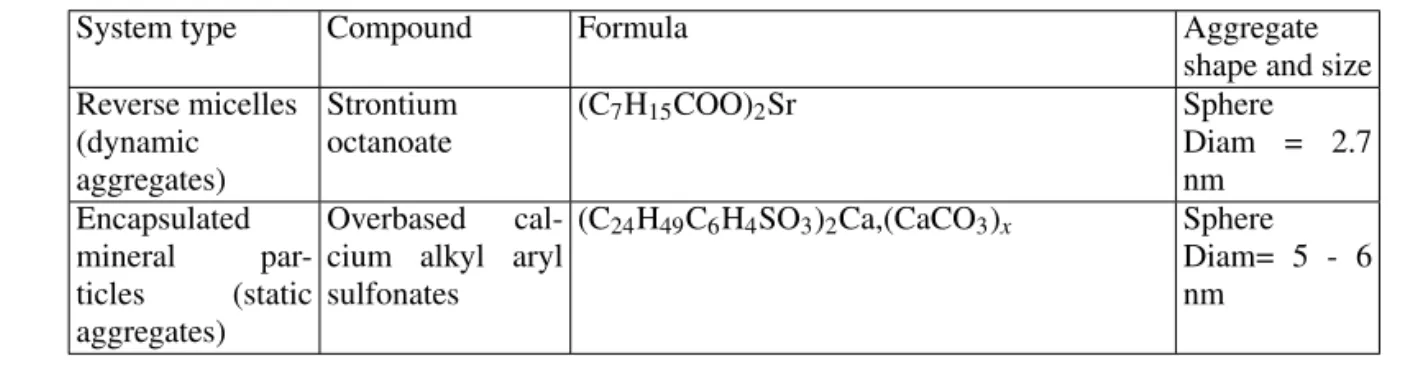
System type Compound Formula Aggregate
shape and size Reverse micelles
(dynamic aggregates)
Strontium octanoate
(C7H15COO)2Sr Sphere
Diam = 2.7 nm
Encapsulated mineral par-ticles (static aggregates)
Overbased cal-cium alkyl aryl sulfonates
(C24H49C6H4SO3)2Ca,(CaCO3)x Sphere Diam= 5 - 6 nm
Table 1: characteristics of the nano lubricant additives chosen as examples.
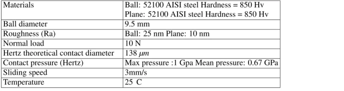
In order to simplify the tribologic results interpretation [62, 63], the colloidal additives are introduced alone in a model mineral base oil of low viscosity, normal dodecane, and the tribologic properties are evaluated using the alternative sphere
Materials Ball: 52100 AISI steel Hardness = 850 Hv Plane: 52100 AISI steel Hardness = 850 Hv
Ball diameter 9.5 mm
Roughness (Ra) Ball: 25 nm Plane: 10 nm
Normal load 10 N
Hertz theoretical contact diameter 138µm
Contact pressure (Hertz) Max pressure :1 Gpa Mean pressure: 0.67 GPa
Sliding speed 3mm/s
Temperature 25 C
Table 2: experimental parameters used for the sphere / plane tribologic tests
Friction reduction and antiwear properties of Sr octanoate reverse micelles
The tribologic results recorded on Sr octanoate and OCABS dispersions in dodecane are compared to those of pure dodecane and classical ZDDP additive solution in dode-cane (figure 15).
FIG. 15: Evolution of Electrical Contact Resistance (ECR), friction coefficient and wear scar width as a function of cycles number for pure dodecane, ZDDP, OCABS and Sr Octanoate in dodecane solu-tions.
In the case of pure dodecane, the ECR remains low (few ohms) and the friction coefficient high (0.7). The correspond-ing wear scar evolution shows an heavy wear characterized after 500 cycles by a wear scar depth of 0.5µm(figure 16). In the presence of 1% ZDDP in dodecane the wear rate is high at the beginning of the experiment and reduces to a very low value after 250 cycles correlatively to the ECR stabiliza-tion (103ohms) corresponding to the end of the well-known induction period necessary for the anti-wear film built up. Af-ter 500 cycles the anti-wear film is easily seen by optical mi-croscopy and the wear scar depth is of 0.2µm.
In the presence of the Sr and OCABS additives, the mea-sured Electrical Contact Resistances are high (105 ohms) and friction coefficients are low (µ=0.13 for Sr additive, µ=0.1 for OCABS) as soon as the tribologic experiments start. These results emphasize the rapid built up of the tribo-active phase on the surfaces at the beginning of the friction experiment. This fast built up results from physicochemical transformations, in the contact conditions, of the nano
parti-cles of additive adsorbed on the friction surfaces. The evolu-tion of the wear rate in these two cases (figure 15) does not reveal any significant wear during the tests. The tribofilms are built on the surfaces (average thickness around 0.15 - 0.2 µm) and the initial surfaces polishing scratches are visible un-der the anti-wear film (figure 16 GH). These results clearly demonstrate the exceptional protective efficiency of such ad-ditives compared to conventional ones.
FIG. 16: Optical micrographs and surface profiles collected onto wear scars obtained after:
- 500 cycles in the presence of pure dodecane (A,B) and 1% ZDDP solution in dodecane(C,D)
- 2000 cycles in the presence of 1% dispersion in dodecane of stron-tium octanoate (E,F), OCABS (G,H). As it can be noticed, the tri-bologic film obtained (around 200 nm thick) in the presence of nano sized additives is built on the initial surfaces whereas in the pres-ence of dodecane or ZDDP, the wear scars have respectively 500 and 200 nm of depth. It is important to note that, in the case of nano-additives, the polishing scratches of the initial surfaces are eas-ily seen (arrows in G) under the partially transparent anti wear film. This fact points out that there is no significant wear (down to few nm) in the presence of the chosen colloidal additives.
Nature and structure of anti-wear films obtained with strontium and calcium compounds
In order to complete the understanding of the action mech-anisms of colloidal additives the nature and structure of anti-wear films obtained in the presence of two representative sys-tems (Sr octanoate dynamic micelles and OCABS particles) are investigated by means of Analytical Transmission Mi-croscopy the main results being presented in figure 17 and 18.
FIG. 17: Dark field transmission electron micrograph and selected area electron diffraction pattern recorded on a tribologic film parti-cle obtained in the presence of Sr octanoate micelles.
The indexation of the electron diffraction pattern allowed us to con-clude that the tribofilm is made of polycrystalline strontianite, the size of the crystallites lying in the range 10-150 nm.
The EDX spectrum does not evidence the presence of iron underlin-ing the high anti-wear properties and the absence of chemical reac-tion with the substrate for the built up of the tribofilm (copper peaks are due to support grid).
The EEL spectrum at carbon K ionization edge mainly reveals the fine structures characteristic of carbonate groups. This indicate that hydrocarbon chains are not significantly present in the film.
carbonate phases, respectively strontianite (Sr octanoate ad-ditive) and calcite (OCABS).
In the case of the OCABS film, electron micro-diffraction patterns carried out between well-identified nano-crystallites demonstrate the existence of an amorphous phase responsi-ble of the cohesion of the film. This phase, not identified by ATEM probably corresponds to (amorphous) calcium oxide species recently detected by Tof SIMS analyses [64].
The EEL spectra collected at carbon K edge on the two films (Figure 17C and 18D) present great differences with the corresponding spectra in the initial additives. The fine structures associated to C=C, C-C and C-H bondings in the initial compounds are not significantly detected in the EEL spectra of the films. These last ones are dominated by the well known fine structures associated to C=O and C-O [52, 62]. These results demonstrate that hydrocarbon chains are no more significantly present in the films implying their quite total elimination during the friction process.
The absence of iron in the tribo-film as revealed by EDXS spectra collected on the two films ( figure 17B and 18C) strongly supports that chemical reactions between the nano additives and the substrates are not involved in the anti-wear film formation. It confirms that induction period is not needed for the tribofilm establishment and then points out the high protective efficiency against wear of such nano-additives.
A significant difference of behaviour for the two additives is evidenced by the size of the micro crystals present in the re-spective films. In the case of OCABS the micro crystals have dimension( 6−10nm)close to the mineral core of the
ini-tial particles (5-7 nm). The crystals present in the strontianite film are readily larger( 10−150nm)than initial micelle’s
cores (1nm) involving a more complex re-crystallisation pro-cess.
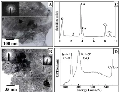
and , transmission electron micrographs and electron diffra
O
0 S
Ca
Ca
Cu
Cu
2 4 6 8 10
Energy Loss (eV) 280 300 320 340 1s ¹ *
C=O
Ca L2,3 1s σσσσ*
C-O 100 nm
35 nm
A
B
C
D
FIG. 18: (A)and(B), transmission electron micrographs and elec-tron diffraction patterns recorded on tribologic film particles ob-tained in the presence of OCABS in dodecane dispersion.
(C),(D)corresponding EDX and EELS spectra. The film is com-posed of nano-crystallites of calcite (diffraction) which average size is 10 nm aggregated by means of ill ordered areas (diffuse diffrac-tion). EDX spectrum reveals that iron is not detected (copper peaks are due to the support grid). EEL spectrum at Carbon K edge is dom-inated by carbonate fine structures and points out that hydrocarbon chains are not significantly detected in the film.
Associated antifriction and anti-wear actions in tribologic behaviour of colloidal additives
The examples chosen to illustrate the tribologic behaviour allow us to draw the various actions of such colloidal addi-tives.
The friction reduction is mainly attributed to the adsorption film of additive (organic molecule, soap molecules or encap-sulated particles). The length of the organic shell (organic chains) is a first order parameter according to Zisman experi-ments (as large is the chain as low is the friction coefficient). The exceptional wear reduction in the wear test is associated to the quasi-instantaneous built up of a stable tribologic film from the adsorbed additive layer. The polycrystalline carbon-ate nature of the film results from the elimination of part of the organic radicals(oxidization) and the crystallization of ill or-ganized cores of the micelles or encapsulated particles under the physical conditions of the sliding contact (P 1Gpa, shear stress 105s−1, oxidative species, flash temperatures. . . ).
It is important to note that the carbonate phases produced in the sliding contact does not present excellent friction reduc-tion properties if used as solid lubricants. Recent experiments [65] demonstrated that a friction coefficient of 0.6 is obtained with surface films of pure polycrystalline calcite. This co-efficient reduces to 0.06 when pure dodecane is added or to 0.1 in the presence of Octanoic acid molecules. These re-sults emphasize the role of the amphiphilic molecules in the inter crystallite interactions responsible of the mechanical be-haviour of the nano-granular tribo-films.
Step 1: adsorption of the additive on the substrate surfaces
Step 2: loss of hydrocarbon chains and crystallization of the mineral part of the colloids under the physico-chemical conditions of the sliding contact (P 1Gpa, shear stress 105 s 1, flash temperature, oxidizing species. . . ).
These transformations do not imply any chemical reaction with surfaces components
Step 3: the tribofilm is worn instead of metal substrates (substitution wear) and regenerated from additive molecules or aggregates adsorbed on its surface.
The role of amphiphilic molecules of the organic surround-ing shell is to reduce friction either by adsorption on the sur-face film or by modifying (lowering) the inter-grains interac-tions.
The anti-wear action works via substitution wear of the tri-bochemical film. This one is continuously regenerated from the additive adsorbed layer. The consumption of additive (apart from the initial adsorption on the whole surfaces) is
se-lectively located in the sliding contact due to the fact that the anti-wear film built up needs the physicochemical conditions of the sliding contact to operate.
II. CONCLUSION AND PERSPECTIVES
Colloidal physics and chemistry offer interesting ways of research in the reduction of friction and wear applied to vari-ous metallurgical contexts. The development of additives that do not involve reaction with contacting substrates and the pos-sibilities to associate in the same colloidal particle corrosion inhibition, friction reduction and anti wear actions are of great interest.
The chemical methods developed in order to produce nano-sized dynamic or static particles will allow the tribologist to design stable dispersion in oil of selected compounds precur-sors of efficient tribochemical film.
[1] D. DOWSON, “History of Tribology, Longmans, London, (1979).
[2] G. AMONTON, M´emoires de Math´ematiques et de Physique de l’Acad´emie Royale des Sciences, p. 206, (1999).
[3] C.A. COULOMB, M´emoires de Math´ematiques et de Physique de l’Acad´emie Royale des Sciences, p. 161, (1785).
[4] H. HERTZ, “Uber die Ber¨urhung fester elastischer K¨orper”, J. reine und angewandte Mathematik, 92, p. 156-171, (1882) [5] R. STRIBECK, Die Wesentlichen Eigenschaften der Gleit-und
Rollenlager, Z. Verein. Deut. Ing. Vol. 46 n 38, p. 1341-1348, (1902).
[6] Sir W.B. HARDY, Collected works, University Press, Cam-bridge, (1936).
[7] K.L. JOHNSON, Contacts mechanics, Cambridge University Press, Cambridge, (1985).
[8] W.A.ZISMAN, “durability and wettability properties of monomolecular films on solids“, friction and wear, R. DAVIES (Ed), Elsevier, Amsterdam, p110-148 (1959).
[9] A.S. AKHMATOV, Molecular Physics of Boundary Friction, IPST, Jerusalem, (1966).
[10] J.M. MARTIN, Contribution a la tribologie: Etude du m´ecanisme d’action d’un additif anti-usure en regime de lu-brification limite. Aspects chimiques dans le cas des organ-odithiophosphates m´etalliques, These d’´etat n 7827, Univer-sit´e Claude Bernard, Lyon, (1978).
[11] J.M. MARTIN, J.L. MANSOT, I. BERBEZIER, H. DEXPERT, ”The nature and origin of wear particle from boundary lubrica-tion with ZDDP”, Wear, 93 (2), p. 117-126, (1984).
[12] J.M. MARTIN, J.L. MANSOT, I. BERBEZIER, M. BELIN, ”Microstructural aspects of lubricated mild wear with zinc dithiophosphate”, Wear,107, p. 355-366, (1986).
[13] J.M. MARTIN,M. BELIN, J.L. MANSOT, ”Friction induced amorphization with ZDDP. An EXAFS study”, ASLE Trans-actions, 49(4), p. 523-531, (1986).
[14] M. BELIN,J.M. MARTIN, J.L. MANSOT, ” Role of iron in the amorphization process in friction-induced phosphate glasses”, Journal de Physique, 48(C9), p. 1147-53 (1987).
[15] J.C. BELL, K.M. DELARGY, A.M. SEENEY, “the removal of substrate material through thick zinc dithiophosphate anti-wear films”. In D. DOWSON et al., editors. Tribology series,
21, wear particles: from the cradle to the grave. Amsterdam. Elsevier; p. 387-96, (1992).
[16] J.M. MARTIN, C. GROSSIORD, T. LEMOGNE, S. BEC, A. TONCK, “The two layers structure of Zndtp tribofilm part 1: AES, XPS and XANES analyses”. Tribol. Int., 31(10), p. 627-44, (2001).
[17] H. SPIKES, “The history and mechanisms of ZDDP”. Tribol. Lett, 17 (3), p. 469-89, (2004).
[18] J.M. MARTIN, “ Lubricant additives and the chemistry of rub-bing surfaces: metal dithiophosphates triboreaction films revis-ited”. Jpn. J. Tribol.42, p9, (1997).
[19] J.M. MARTIN, “Antiwear mechanisms of zinc dithiophos-phate: a chemical hardness approach”. Tribol. lett., 6, p.1- 8, (1999).
[20] W. HIRST and A.J. MOORE, Proc. Roy. Soc. Lond., A 365, p. 537-565, (1979).
[21] J.L. MANSOT, “Aspect microscopique de l’action des reduc-teurs de frottement en lubrification limite”, Docteur Ingenieur Thesis, Ecole Centrale de Lyon, (1982).
[22] J.L. MANSOT, J.M. MARTIN, ”In situ measurements of thick-ness thin variations of boundary films by means of tunnel-ing conductivity”, proceedtunnel-ings of the Leeds-Lyon Symposium, (1983).
[23] G.A. TOMLINSON, Phil. Mag. Ser., 7, p. 905, (1929). [24] P. BILAS, L. ROMANA, F. BADE, K. DELBE, and J.L.
MAN-SOT, “Speed and atmosphere influences on Nanotribological properties of NbSe2” , Tribology Letters, vol 34 n 1, p41, (2009).
[25] S.N. POSTNIKOV, Electrophysical and electrochemical phe-nomena in friction, cutting and lubrication p. 113-114, Van Nostrand Reinhold comp., London, (1978).
[26] J.M. GEORGES and T. MATHIA, J. Mech. Appl., vol.2, p 231-266, (1978).
[27] J.L. MANSOT, V. GOLABKAN, L. ROMANA, Ph. BILAS, E. ALLEMAN, Y. BERCION, “Tribological and physicochem-ical characterization of strontium colloidal additives in mild wear regime”, Coll. and Surf. A, vol. 243, p67, (2004). [28] S. COHEN, L. RAPOPORT, E. A. PONOMAREV, H.
W; X=S,Se)”, Thin Solid Films, vol. 324, p. 190, (1998). [29] R. TENNE, M. HOMYONFER, and Y FELDMAN,
“Nanopar-ticles of layered compounds with hollow cage structures, Chemistry of materials”, vol 10(11), p. 3225, (1998).
[30] P. THOMAS, K. DELBE, D. HIMMEL, J.L. MANSOT, K. GUERIN, M. DUBOIS, C. DELABARRE, A. HAMWI, “Tri-bological properties of low-temperature graphite fluorides. In-fluence of the structure on the lubricating performances”, J. Phys. Chem. Solids, vol. 67, n 5-6, p. 1095, (2006).
[31] L. RAPOPORT, Y. FELDMAN, M. HOMYONFER, H. CO-HEN, J. SLOAN, J.L. HUTCHISON, and R. TENNE, “In-organic fullerene like materials as additives to lubricants: structure-function relationship”, Wear, vol. 225-229, p. 975, (1999).
[32] L. RAPOPORT, Y. BILIK, Y. FELDMAN, M. HOMYONFER, S.R. COHEN and R. TENNE, “ Hollow nano-particles of WS2 as potential solid state lubricants, Nature, vol. 387, p. 791, (1997).
[33] J.J. HU and J.S. ZABINSKI, “Nanotribology and lubrication mechanisms of inorganic fullerene like MoS2 nanoparticles in-vestigated using lateral Force Microscopy”, Tribology letters, vol. 18 (2), p. 173, (2005).
[34] L. JOLY-POTTUZ, F. DASSENOY, M. BELIN, B. VACHER, J.M. MARTIN, and N. FLEISHAUER, “Ultra low friction and wear properties of IF-WS2 under boundary lubrication, Tribol-ogy letters, vol. 18 (4), p. 477, (2005).
[35] P. Thomas, K. Delbe, D. Himmel, J.L. Mansot, M. Dubois, K. Guerin, W. Zhang, A. Hamwi, ”Tribological properties of fluorinated carbon nanofibres”, Tribology Letters, vol.34 n 1, p.49, (2009).
[36] J.L. MANSOT, K. DELBE, P. THOMAS, “tribo-synthesis of graphite Lithium intercalated compounds”, proceedings of the Am. Chem. Soc. Meeting, New Orleans , (2008).
[37] D. LANGEVIN in P.L. LUISI and B.E. STRAUB (Eds.), “Re-verse Micelles”, Plenum, New York, p.287, (1982).
[38] K.L. MITTAL and P. MUKERJEE,”The wide word of mi-celles”, Micellization, Solubilization and Microemulsions vol. 1, K.L. MITTAL (Ed.), Plenum, New York, p1-22, (1977). [39] H.F. EICKE, ”Micelles in apolar media”, Micellization,
Sol-ubilization and Microemulsions vol. 1, K.L. MITTAL (Ed.), Plenum, New York, p. 429-444, (1977).
[40] R. MAKLOUFHI, J.L. MANSOT, E. HIRSH, J. WERY, S.J. CANDAU, J.P. THOMAS and J.P. ROLLAND, ”Electron Mi-croscopy and Light Scattering Study of Organometallic Inverse Micellar Systems”, Colloid & Polymer Science, 273, p. 242, (1995).
[41] J.L. MANSOT, J.M. MARTIN, S.J. CANDAU, ”Amphiphilic complex ester as lubricant additive. Part one : Structure of paraffinic solutions”, Coll. and Surf.,7, p. 301, (1983). [42] E.L. BENEDETTI and P. FAVARD, “Freeze Etching
Tech-niques and applications”, Soci´et´e Franc¸aise de Microscopie Electronique, (1973).
[43] MARTIN, MANSOT, HURIER et MAROTEL,”Savons de cal-cium possedant une r´eserve de basicit´e ´elev´ee”, international patent n 85/19393, (1985).
[44] J.R. WITTLE, “Method of preparing overbased calcium sul-fonates”, US patent n 4,427,559 (1984).
[45] C.BELLE et al, “M´ecanismes des reactions polyphasiques: cin´etique de formation de carbonate de calcium colloidal en milieu apolaire”, J. Chim. Phys., 87, p.93-104 (1990). [46] L.K. HUDSON, J. EASTOE and P.J. DOWDING,
“Nanotech-nology in action : overbased nanodetergent as lubricant oil ad-ditives“, Advances in Coll. and Interf. Sci., 123-126, p.425-431, (2006).
[47] ] J. WERY-VENTURINI, “contribution a l’´etude de la structure microscopique de micelles inverses d’octanoate de plomb”,
These de doctorat, Universit´e de Nantes (1992).
[48] J. WERY and J.L. MANSOT, ”Quantitative study of irradia-tion damage in organometallic collo¨dal particles”, Microsc. Microa. Microstruc., vol. 4, n 1, (1993).
[49] J.L. MANSOT, J. WERY and P. LAGARDE, “Local Structure Analysis of the mineral core of reverse micelles in dispersion in Hydrocarbons”, Colloids and Surfaces, 90, p.167-182, (1994). [50] J.M. MARTIN, J.L. MANSOT and M. HALLOUIS, ”Energy filtered electron microscopy (EFEM) of overbased calcium alkylaryl sulfonate micelles”, Ultramicroscopy , 30, p. 321-328, (1990).
[51] t [51] - J.M. MARTIN, J.L. MANSOT, M. HALLOUIS and H. TENAILLEAU”, High Resolution Electron Spectroscopic Imaging (ESI) of Reverse Micelles”, Microscopy, Microanaly-sis, Microstructure, 2,p.1-8, (1990).
[52] J.L. MANSOT, M. HALLOUIS and J. M. MARTIN, ”Col-loidal antiwear additives Part One : Structural study of over-based calcium alkylbenzene sulfonate micelles”, Colloids and Surfaces A, 71, p. 123-134, (1993).
[53] J.L. MANSOT, V. GOLABKAN, L. ROMANA, Th. CE-SAIRE, “Chemical and physical characterization by EELS of strontium hexanoate reverse micelles and strontium carbon-ate nanophase produced during tribological experiments”, J. of Micr., vol. 210, p. 110, (2003).
[54] J.M. MARTIN, M. BELIN, J.L. MANSOT, ”EXAFS of cal-cium in overbased micelles”, Journal de Physique, vol. 12 n 47, p. 887-890, (1986).
[55] t [55] J.L. MANSOT, J.M. MARTIN, H. DEXPERT, D. FAURE, P. HOORNAERT and R.GALLO, ”Local structure analysis in overbased reverse micelles”, Physica B,158, p. 237 (1989).
[56] L. CISAIRE, J.M. MARTIN, T. LEMOGNE and E. GRESSER, “Chemical analysis of overbased calcium sulfonate detergents by coupling XPS, Tof-SIMS, XANES and EFTEM, Coll. and Surf. A:Physicochem. Eng.Aspects, 238, p.151-158, (2004).
[57] I. MARKOVIC, R.H. OTTEWILL, D.J. CEBULA, I. FIELD and J.F. MARSH, “Small angle neutron scattering studies on non aqueous dispersions of calcium carbonate Part 1 Guinier approach”, Colloid and Polym. Sci., 262, p.648 (1984). [58] I. MARKOVIC, R.H. OTTEWILL, D.J. CEBULA, I. FIELD
and J.F. MARSH, “Small angle neutron scattering studies on non aqueous dispersions of calcium carbonate Part 2”, Colloid and Polym. Sci., 264, p.265-276 (1986).
[59] S. GIASSON, D. ESPINAT, T. PALERMO, R. OBER, M. PESSAH and M. F. MORIZUR,“Small angle X-Ray scattering (SAXS) on calcium sulfonate dispersions: effects of friction on microstructure“, J. of Coll. and Interf. Sci., 153(2), p. 355-367, (1992).
[60] S. GIASSON, T. PALERMOA, T. BUFFETEAU, B. DESBAT and J. M. TURLET, “ Study of boundary film formation with overbased calcium sulfonate by PM-IRRAS spectroscopy “, Thin Solid Films, 252, p. 111-119, (1994).
[61] E. R. ARNDT and K. L. KREUZ,“ Characterization of calcium alkylaryl sulfonates containing encapsulated solids“, J. of Coll. and Interf. Sci., 123, p. 230-237, (1988).
[62] J.L MANSOT, M. HALLOUIS and J.M MARTIN, “Colloidal antiwear additives - Part two : Tribological behaviour of col-loidal additives in mild wear regime”, Colloids and Surfaces A, 75, p. 25-31, (1993).
[63] J.L. MANSOT, V. GOLABKAN, L. ROMANA, Ph. BILAS, E. ALLEMAN, Y. BERCION, “Tribological and physicochem-ical characterization of strontium colloidal additives in mild wear regime”, Coll. and Surf. A, vol. 243, p. 67 (2004). [64] T. KUBO, S. FIJIWARA, H. NANAO I. MINAMI, S. MORI,
sulfonates“, Tribo. Lett., 23(2), p.171-176,(2006).
[65] J.L. MANSOT, ”Nanolubrication, the colloidal approach”,

![FIG. 6: Schematic structure of the ZDDP tribo-film according to the multi techniques approaches [16]](https://thumb-eu.123doks.com/thumbv2/123dok_br/18983362.457899/3.977.510.898.802.1058/schematic-structure-zddp-tribo-film-according-techniques-approaches.webp)

![FIG. 8: Aspect of polymeric micelles (viscosity index improver and friction reducer [21, 40]) in dodecane as observed by means of trans-mission electron microscopy on a platinum shadowed replica pre-pared by the freeze fracturing technique](https://thumb-eu.123doks.com/thumbv2/123dok_br/18983362.457899/5.977.96.452.75.349/polymeric-micelles-viscosity-improver-friction-microscopy-fracturing-technique.webp)