www.adv-radio-sci.net/9/61/2011/ doi:10.5194/ars-9-61-2011
© Author(s) 2011. CC Attribution 3.0 License.
Radio Science
Motion compensation of short-range, wide-beam synthetic
aperture radar
T. Reichthalhammer and E. Biebl
Fachgebiet H¨ochstfrequenztechnik, Technische Universit¨at M¨unchen, Munich, Germany
Abstract. Up to now, SAR systems are a well known pos-sibility for long-range detection. Applying them for short-range applications with wide-beam antennas, of course, does not increase the resolution but the probability to detect hid-den targets with an anisotropic radar cross section signifi-cantly in comparison to other detection systems. Working with an appropriate wavelength even improves the possib-lity to look through natural cover like grass. An application is detecting fawn while pasture mowing. The main issue in such applications is the antenna’s motion in range direction as it is carried by cars or traction engines. If motion is not compensated, the phase cannot be reconstructed correctly, the resolution gets poorer and, in worst case, the target even disappears. Conventional methods for motion compensation either fail for wide beam antennas, since for contributions of wide angles the phase reconstruction is incorrect, or is not applicable for realtime data processing, because the process-ing time due to interpolation or similar steps is very high. We present a method of image reconstruction regarding mo-tion of the antenna as well as wide beamwidth. This method is analyzed concerning processing time in comparison to the conventional image reconstruction. In our system we use a combination of algorithms. There is shown a comparison for different algorithms dependent of the antenna’s motion and aperture angle.
Correspondence to: T. Reichthalhammer ([email protected])
1 Introduction
One of the main characteristics of an SAR system is its inde-pendence of the distance between the antenna and the targets concerning the resolution in azimuth direction. That means the resolution stays constant with varying distance. Anyhow a short-range SAR system has advantages, first and foremost a wide-beam system (Gerbl, 2007). Such a system can be used for imaging in automotive applications or in farming to detect wild animals. (Reichthalhammer, 2010) The prob-ability of detection increases if the aperture angle becomes larger since the target is illuminated from different angles. The contributions of e.g. a point scatterer are summed up in proper phase relation. The bigger the aperture angle, the more contributions and the better the contrast in the image.
The quality of an SAR image depends on the accuracy of the phase reconstruction of the single signal contributions of different angles. A consequence of a phase error is a picture with degradation in contrast and resolution. To achieve an exact phase rotation one has to know the exact position of the antenna at each recording point. This issue enlarges if the antenna is not carried by a plane but by a vehicle and the ground is bumby. So motion compensation requires an exact detection of the position and an appropriate signal processing algorithm regarding wide beam contributions.
x
y z
D
h +dz
-dz
r0
dy
r
Fig. 1.Coordinate system.
2 System setup
Short-range radar imaging with wide-beam antenna is dis-cussed detailed in (Gerbl, 2007). An applicable signal source therefore was developed in (Reichthalhammer, 2010). The crucial point of wide-beam systems is the fast growing doppler bandwidth that postulates a high sample rate. In turn this means a high data volume and a longer processing time. In addition the doppler bandwidth and the processing time is even enlarged if motion has to be compensated. In Fig. 1 the coordinate system of the setup is shown.
The azimuth direction of the system is x, the range direc-tion r0 is perpendicular to the azimuth direction. The
de-pression angleǫDis the angle between the x-y-plane and the
antenna.
3 SAR imaging
The general way to reconstruct a recorded scene in azimuth direction is a convolution of the recorded signal with the complex conjugate signal of a point scatterer for each line dyof the picture. Our system works in a stop-and-go manner
and the doppler frequency caused by the motion of the vehi-cle can be neglected. So for a stepped frequency system the equation therefore is
x[l] =
+r0tanα X
l=−r0tanα
x1[n] ·x2[l−n], (1)
wherex1 is the SAR system response and x2 the complex
conjugate function ofx1.
Because the illuminated area enlarges with growing dis-tance to the antenna, the compensation function changes with varying distance (Klausing, 2000). The real part of the
re-0.2 0.4 0.6 0.8 1 1.2 1.4 1.6 1.8
0.6 0.7 0.8 0.9 1 1.1 1.2 1.3
0 500 1000 1500 2000 -1 -0.5 0 0.5 1
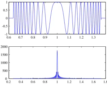
Fig. 2. real part of received signal and magnitude of compressed signal.
azimuth [m]
ra
n
g
e
[m
]
0 0.5 1 1.5 2 -30
-25 -20 -15 -10 -5 0
0.4 0.6 0.8 1 1.2 1.4 1.6
Fig. 3.SAR picture of a point scatterer, 1.8GHz bandwidth, scaled to its maximum.
a distance r0=1m and an aperture angle of 20◦is depicted in
Fig. 2 assumed constant directivity of the antenna.
The resulting function Fig. 2 is a compression of the spa-tially extendend received signal with a peak at the position of the target. Obviously the phase velocity increases with in-creasing angles. The spatial doppler frequency is zero, where the target is located. To get resolution in range equidistant frequency steps inside a given bandwidth are necessary. This results in an unambiguous range which is treated in (Re-ichthalhammer, 2010). Conventional SAR imaging uses a two dimensional Fourier transformation of the signal s(x,t) into s(kx,ω) as described e.g. in (Soumekh, 1999). Since our
dz
r0
r - dz0
dz
Fig. 5
xt x
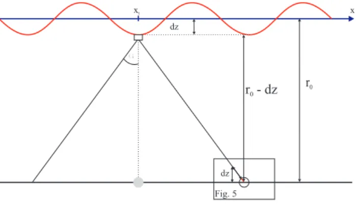
Fig. 4. Occuring compensation error due to antennas movement dependent of aperture angle.
Usually the wavefront curvature cannot be neglected what enforces a transformation of the data from polar into carte-sian coordinates. This step can be circumvented if the range stacking algorithm is used (Soumekh, 1999). At range stack-ing for each given range bin the azimuth compressed signals for each frequency are added what yields the range resolu-tion. This way even for wide beam antennas an interpolation can be avoided and computational time saved.
4 Motion in short-range SAR systems
In a 3-dimensional space in principle all 6 degrees of freedom have to be considered. A translational motion in x, y and z-direction and a rotatory motion around each axis (pitch, gear, yaw). In our case a few assumptions are done to simplify the problem. Supposed that only a rotation around x exists along the path x, the target would appear at different positions y in the antenna’s field of view. In worst case -depending on the aperture angle in range and the rotation- the target would even disappear. To compensate this rotation the antenna pat-tern has to be multiplicated inverse to the image columns. Rotations around y and z can be neglected, since a huge turn radius of the vehicle and a little curvature of the ground in respect of a short aperture timeTSA - the time one target is
illuminated by the antenna.
Assumed that the vehicle moves straight ahead the az-imuth direction during one synthetic aperture timeTSA one
can neglect the translational motion in y as well. As de-scribed in (Reichthalhammer, 2010) the system records data along its path x equidistantly independent of the velocity. Hence a quasi static system is supposed in azimuth direction and motion compensation is not necessary. So the system’s movement is reduced to an oscillation in z and a rotation8
around x which hase to be considered. So the 6-dimensional problem can be reduced to a 2-dimensional problem. For fur-ther calculation and simulation even the rotation is neglected.
dz
err dz
d
Fig. 5.Magnification Fig. 4.
5 Motion compensation vs. processing time
To reconstruct a recorded scene correctly, the main postula-tion to an SAR system is, that its trajectory has to be known. Simplified a rectilinear trajectory can be assumed, but carried by a vehicle an SAR system cannot follow a straight line. A solution is to detect the motion and rotation and compensate it. For this purpose different algorithms are recommended in literature. The majority of these algorithms try to detect the deviation either by inertial measurement supported by GPS or by analyzing the received signal. Afterwards the re-ceived data is manipulated, what means that the phase and the amplitude are corrected. This procedure holds for the case of a small aperture angle and is know as the narrow-beam-assumption. For increasing aperture angles these algorithms become defective. The error appears since the reconstruction of the phase is done for each recording point, which corre-sponds to a column in the SAR picture. If the aperture angle of the antenna becomes bigger each data point can contain in-formation of an object far away from the perpendicular, but a translatory deviation of the antenna always is a term perpen-dicular to the trajectory. For example the signal of a point scatterer at distanceris
s=a·exp(−2jkr) (2)
where a is an amplitude term andk=2λπ the wavenumber. With classical compensation like the 2-D Fourier method the singular data point is treated as it only contains informa-tion of the scene perpendicular to the trajectory. For example, the distance r between a sphere and an antenna forr0=1m and α=20◦degree as depicted in Fig. 4 varies with a deviation of the antenna at xnin +z-direction. The magnification of the
0.6 0.8 1 1.2 -1
0 1
Fig. 6.real part of received signal with motion, f=24GHz,α=20◦, 5 Hz/aperture, a=0.1m,ǫD=45◦.
To compensate this deviation the data at point xnis
manip-ulated by a phase term
s=a·exp(−2jkr)·exp(−2jkdzsinǫD). (3)
dz can be positive or negative. In case of a small
beamwidth the variation of dz over the angle can be
ne-glected. Higher angles cause too less phase subtraction in case of motion in+dz-direction and too much phase
addi-tion in case of moaddi-tion in−dz-direction.
The absolute error can be defined as
derr=
|dr|
cosα− |dr|, (4)
whereα is the angle between target and antenna as de-picted in Fig. 4 and|dr| = |dz|sinǫD.
If an arbitrary harmonic deviation is introduced to the an-tenna’s trajectory with an amplitude of 10 cm and 5 oscilla-tions per synthetic aperture withǫD=45◦, which is a realistic
assumption, the real part of the received signal is depicted in Fig. 6. Hence the typical chirp-like signal form of Fig. 2 is lost. In case of no compensation, the SAR picture of a point scatterer is depicted in Fig. 7.
If compensated with the narrow-beam assumption the sig-nal is filtered as described by Eq. (1) and the picture of Fig. 7 turns to Fig. 8. The maximum of the target decreases, side-lobes appear and the resolution in azimuth decreases signifi-cantly, but the processing time itself stays constant.
Note that for using the SAR system for nearly real-time image processing, due to actual processor capabilities the biggest issue is to find a way between sufficient contrast and short processing time. Since there are no smooth transitions between and algorithms mainly focus on one of both sides respectively, one cannot do a compromise.
A well known solution that avoids errors appearing for higher aperture angles is the SAR backprojection algorithm, see (Soumekh, 1999). This algorithm works as follows: SAR data firstly is filtered in range. For each pixel its contribu-tionsdr to the relevant part of the SAR data is reconstructed
and vectorial multiplicated with the corresponding SAR data
azimuth [m]
ra
n
g
e
[m
]
0 0.5 1 1.5 2 -30
-25 -20 -15 -10 -5 0
0.4 0.6 0.8 1 1.2 1.4 1.6
Fig. 7.SAR picture of a point scatterer, 1.8GHz bandwidth, scaled to its maximum, uncompensated motion.
dz
err dz
d
Fig. 8.SAR picture of a point scatterer, 1.8GHz bandwidth, scaled to its maximum, conventional motion compensation.
of the pixel. This way even a translational motion of the an-tenna can be compensated, but note that the data have to be filtered in range before, what does not fit to the range stack-ing algorithm, where an azimuth compression of the data in the first step is compellent. Moreover this algorithm causes a high processor load as treated later. The equation for back-projection is
x[n] =
n+(r0−dz)tanα X
l=n−(r0−dz)tanα
sazn[l] ·sdr[l], (5)
wherexdr is the signal different at each pointn.
FFT
x→kx
IFFT
s(x,wj)
s∗
0j(x,wj)
S(kx,wj)
f(x,wj)
FFT
x→kx S∗0j(kx,wj)
P
j
f(x,y) motion
comp
for every range line y
Fig. 9.SAR signal processing with and without motion compensa-tion with narrow beam assumpcompensa-tion.
P
l
s
(
w
j,l
)·
s
∗(
w
j,l
)
P
j
s(x,w
j)
s
∗(l,w
j)
f(x
i,w
j)
f(x,y)
for every range line y
Fig. 10.SAR signal processing with combination of range stacking and backprojection algorithm.
Furthermore the interpolation step of the backprojection algorithm in azimuth direction does not have to be done with our system since the image resolution in azimuth and sorij
inherently are defined by the sampling space1x.
In Fig. 9 our processing of the SAR signal is shown with and without motion compensation (dashed box) with the nar-row beam assumption, which leads to an image as shown in Fig. 8. The processing has to be done for each range line y. To achieve range resolution with range stacking the results for different frequencies are calculated and added each time. In Fig. 10 the processing is shown if wide beams and other image degrading effects have to be considered. One can see, that nothing of the 2-D Fourier algorithm is left. In both di-mensions the processing is substituted by a summation. For each range line, each pixel is processed concerning its re-flectivity, as described above. Each range line has to be pro-cessed for each frequency. The results for one range line are summed up vectorialy. This way, the picture is reconstructed like the one depicted in Fig. 11.
A comparison for one range line dr=1m is made in Fig. 12.
In the upper figure the reconstruction of a point scatterer without motion is depicted in comparison to the processing result if a typical motion is not compensated. If not com-pensated, the image contains no information as depicted in Fig. 7. In the lower figure the results are shown for both, a compensation as described in Fig. 9 and a compensation as treated in Fig. 10.
azimuth [m]
ra
n
ge
[m
]
0 0.5 1 1.5 2 -30
-25 -20 -15 -10 -5 0
0.4 0.6 0.8 1 1.2 1.4 1.6
Fig. 11.SAR picture of a point scatterer, 1.8 GHz bandwidth, scaled to its maximum, motion compensation with derivative of backpro-jection algorithm.
azimuth
am
p
li
tu
d
e
signal without oscillation
signal with oscillation uncompensated
azimuth
am
p
li
tu
d
e
SAR data compensated response function compensated
0.2 0.4 0.6 0.8 1 1.2 1.4 1.6 1.8
0.2 0.4 0.6 0.8 1 1.2 1.4 1.6 1.8
0 500 1000 1500 2000 0 500 1000 1500 2000
Fig. 12.comparison of SAR signal reconstruction at one range line for no motion, motion without compensation, motion with different compensation methods.
6 Processing time
An estimation of the processing time can be done. Therefore a reference processing time have to be defined. In our case this is the processing time without motion compensation as depicted in Fig. 9, that can be described as a 1-D Fourier algorithm with range stacking.
O=y[x·log2(x)
| {z }
FFT
·f+ x·f
|{z}
summation
] =
=y·x·f[log2(x)+1]. (6)
If the SAR raw data is manipulated the processing load of Eq. (6) is extended by the termxand reads as
O=y·x·f[log2(x)+1] +x. (7)
In the case of motion compensation as depicted in Fig. 10 the processing loadOincreases to
O=y· [l·log2(l)·f·x
| {z }
FFT
+ f·x
|{z}
multiplication
+ x
|{z}
summation
] =
=y·x·f[l+x+1
f], (8)
where l is the number of data points inside a synthetic aper-ture dependent on the range and the aperaper-ture angle. As ex-plained above there is a huge gap between the two ways of motion compensation regarding processing time increasing with the aperture angle. A possible solution for time critical systems where only one target per synthetic aperture is ex-pected is to process the image at first with the fast algorithm and postprocess the parts of the image where an aim is de-tected with the slow algorithm. But note, that this method fails if more than one target appears inside one synthetic aperture. If this is not guaranteed, one has to decide between image quality and processing time.
7 Conclusions
In this paper we dicussed the motion compensation intro-duced to an SAR system working in short-range with wide-beam antennas. We explained the setup and application of our radar system and show the difference between the algo-rithms charged by a motion compensation term and a new one, which is a derivation of the backprojection algorithm combined with the range stacking algorithm. The gap be-tween high resolution and fast processing is analyzed and a proposal for processing special target scenes made. Simula-tion results are depicted and processing time is compared to the original algorithm.
References
Gerbl, F.: Evaluation of wide-beam, short-range synthetic aperture radar imaging, Ph.D. thesis, TU Muenchen, 2007.
Klausing, H. and Holpp, W.: Radar mit realer und sysnthetischer Apertur, 2000.
Soumekh, M.: Synthetic Aperture Radar Signal Processing with MATLAB Algorithms, 1std edn., 1999.