Abs tract
This paper attempts to present a new analysis for dynamical be-havior of two-layer beams with frictional interface which held together in a pressurized environment, including stick-slip nonlin-ear phenomenon. To achieve a proper outlook of two-layer beam structures behavior, it is essential to realize the mechanisms of motion precisely. Coupled equation of transversal and longitudinal vibration of two-layers in the presence of dry friction is derived and nondimensionalized. Furthermore, free and forced vibration of the mentioned system is investigated and the system dynamics is monitored via Poincare maps and Lyapunov exponent analysis. A comparative study with ANSYS is developed to show the accuracy of the proposed approach.
Key words
Stick-slip phenomenon, Two-layer beam, Interlayer slip, Frictional interfaces, Chaotic motion.
Stick-slip analysis in vibrating two-layer beams with frictional
interface
1 INTRODUCTION
Mechanical systems in which components are constrained through friction contact surfaces often lead to complex contact kinematics involving slip nonlinear motions. The explanation of stick-slip intermittent motion is based on the instantaneous drop from a static friction force to a constant kinetic friction force. Accurate analysis of layered structure dynamical behavior with frictional in-terface in a pressurized environment requires accurate modeling of dry friction to realize exactly the stick-slip regimes. In the case of layered beams, one of the earliest works was developed by Good-man and Klumpp [1], where the emphasis has revolved around the maximum amount of energy dissipation for two-layered beam in the case of dynamic loading. Badrakhan [2] derived the energy dissipated by Coulomb friction and optimum pressure for maximum energy for any number of lay-ers.
Damisa et al. [3] investigated the effect of the non-uniformity in interfacial pressure as well as the frequency of the driving load, in the context of energy dissipation and logarithmic damping decrement. In the mentioned study, they consider the simple governing equation of motion with pure slip assumption. They extended their analysis to incorporate the effect of relative sizes or the material properties of layered beams of two dissimilar materials and laminate thicknesses [4].
H am id M . Se di g hi*, a Kou ros h H. Sh iraz ib Kh osro N ad era n- Ta hanb
a Mechanical Engineering Department, Shahid
Chamran University, Ahvaz, 61357-43337 Iran,
b Shahid Chamran University, Ahvaz, Iran
Received 23 Jul 2012 In revised form 08 Jan 2013
Latin American Journal of Solids and Structures 10(2013) 1025 – 1042
Li et al. [5] presented an algorithm for solving the static contact problem in a multi leaf spring, whereas the frictional effect has not been taken into account in their research. Awrejcewicz et al. [6] investigated the chaotic vibrations of multi-layered Euler- Bernoulli and Timoshenko type beams for a series of boundary conditions. They verified the reliability of the obtained results via Finite Element and Finite Difference Method. In the work by Awrejcewicz and Krysko [7] an iterative algorithm was proposed to solve efficiently one-sided interaction between two rectangular plates within the Kirchhoff hypothesis supplemented by physical nonlinearities. Furthermore, a novel iter-ation procedure for dynamical problems was introduced by Awrejcewicz et al. [8], where in each time step a contacting plate zone are improved. The chaotic dynamics of multilayer mechanical beam structures was studied by Krys’ko et al. [9]. They took into account physical, geometrical, and contact nonlinearities and developed a method for studying phase synchronization using wave-let analysis and the Morwave-let wavewave-let method.
There are many mechanical systems with friction-engaged subsystems such as brakes, clutches, gas turbine blade roots and machine tools. Such self-excited oscillations have been extensively stud-ied as reviewed in [10]. A spring-block model with a single degree-of-freedom has explained the be-havior of stick-slip oscillations [11]. Kang et al. [12] focused on the dynamic pattern during the steady-state oscillation of spring-block models, with definition of continuous friction curve for dry friction. Awrejcewicz et al. [13] considered two coupled oscillators with negative Duffing type stiff-ness which was friction-induced and externally excited and investigated stick-slip chaotic behavior of the system.
Lyapunov exponents measure the exponential rates of divergence or convergence of nearby tra-jectories in state space. If such equations for the system are non-smooth, the estimation of Lyapun-ov exponents is not straightforward [14]. A nLyapun-ovel dry friction modeling and its impact on LyapunLyapun-ov exponent estimation was proposed by Awrejcewicz et al. [15]. A simple friction law was implement-ed by Licsko and Csernak [16] to primplement-edict the chaotic regimes of well-known spring-block model. The most efficient methods for estimation the largest lyapunov exponent (LLE) using chaos synchroni-zation have been introduced by Stefanski et al. [14, 17].
The main objective of the present study is to identify the stick-slip dynamical behavior of lay-ered beams with frictional interfaces. In this regard, coupled vibrational equation of motion in the transverse and longitude directions is derived. The nonlinear partial differential equations of motion have been reduced by implementation of the Bubnov-Galerkin method. Quasi-periodic and stick-slip chaotic motion of layered beams are investigated. Finally, to indicate the accordance of the pro-posed approach with finite element analysis, a comparative study with ANSYS is developed.
2 GOVERNING DIFFERENTIA EQUATION OF TWO-LAYER BEAM
Latin American Journal of Solids and Structures 10(2013) 1025 – 1042 Figure 1 Configuration of two layer beam under dynamic loading
Figure 2 Free-body diagram of a differential element of two layer beam
Assume that each layer here is the Euler-Bernoulli beam and the vertical displacements of two layers is the same. The symbols w, u
1 and u2 denote the displacements of a point in the middle
plane of the flexible beam in y and x direction for top and bottom layers, respectively. The lateral dynamic equation for differential segment of the beam can be expressed in the following form:
pdx−pdx+Q−Q−dQ−F t
( )
δ(
x−L)
dx =m dx∂2w
∂t2 (1-a)
∂Q
∂x +m ∂2w
∂t2 =F t
( )
δ
(
x−L)
(1-b)where m=A
1ρ1+A2ρ2 denotes the mass per unit length. Neglecting the effect of rotary inertia, the conservation of the angular momentum about the z-axis gives:
−M +M +dM −
(
Q+dQ)
dx =0 (2-a)∂M
Latin American Journal of Solids and Structures 10(2013) 1025 – 1042 the total bending moment M can be formulated as
M =M
1+M2−N1d (3)
where d is the center to center distance of two layers. The condition of absent external axial forces leads to
N =N
1+N2 = 0, N1 =−N2 (4)
combining Eqs. (1-b) and (2-b) yields
∂2M
∂x2 + m∂
2w
∂t2 =
F t
( )
δ(
x−L)
(5)The longitudinal governing equations of motion for top layer is given by the following
−N
1+N1 +dN1+Tdx =m1dx ∂2u
1
∂t2 (6-a)
∂N
1
∂x +
T x
(
,t)
=m1
∂2u 1
∂t2 (6-b)
where T x
(
,t)
is the friction force transmitted between the two layers. Furthermore, the constitu-tive relations can be expressed as:
M
i =EiIi ∂2w
∂x2 (7-a)
N
i =EiAi
∂u i
∂x (7-b)
Substituting Eqs. (7-a) and (7-b) into Eq. (3) yields
M = E
1I1+E2I2
(
)
∂2w ∂x2−E 1A1
∂u 1
∂x
d (8)
Latin American Journal of Solids and Structures 10(2013) 1025 – 1042 ∂2
∂x2
E
1I1+E2I2
(
)
∂2w ∂x2−E
1A1
∂u 1 ∂x d ⎡ ⎣ ⎢ ⎢ ⎤ ⎦ ⎥ ⎥+m
∂2w
∂t2 =
F t
( )
δ(
x−L)
(9)Using Eq. (7-b), the dynamic equation (6-b) can be simplified as below:
∂ ∂x
E 1A1
∂u 1 ∂x ⎛ ⎝ ⎜⎜ ⎜⎜ ⎞ ⎠ ⎟⎟
⎟⎟+T x
(
,t)
=m 1∂2u 1
∂t2 (10)
and the vibrational equation of longitudinal motion for the bottom layer can be obtained as
∂ ∂x
E 2A2
∂u 2 ∂x ⎛ ⎝ ⎜⎜ ⎜⎜ ⎞ ⎠ ⎟⎟
⎟⎟ −T x
(
,t)
=m 2∂2u 2
∂t2 (11)
The Coulomb type of friction, where the friction force is proportional to the normal reaction, is considered in this paper. The general model to describe a dry friction force T x
,t
(
)
is given byT ≤µp x
( )
=TsT =µp x
( )
sgn(
urel)
⎧ ⎨ ⎪ ⎪ ⎪ ⎩ ⎪ ⎪ ⎪
if u
rel =0 (stick), if u
rel ≠0 (slip),
(12)
where u
rel is the interlayer slip velocity assumed between the layers at the interface. As indicated in Fig. 3, it can be found as [18]
u
rel =u2−u1+ ∂ ∂t
∂w ∂x
h 1+h2
2 ⎛ ⎝ ⎜⎜ ⎜⎜ ⎞ ⎠ ⎟⎟ ⎟⎟ ⎡ ⎣ ⎢ ⎢ ⎤ ⎦ ⎥
⎥=u2−u1+
∂ ∂t ∂w ∂x d ⎡ ⎣ ⎢ ⎢ ⎤ ⎦ ⎥ ⎥ (13)
Latin American Journal of Solids and Structures 10(2013) 1025 – 1042
By introducing the following non-dimensional variables
τ= ωt, w*=w L, u i * = u i L,
x*= x
L (14)
the non-dimensional nonlinear equations of motion can be written as
∂4w
∂x4 −6
α
∂3
u1
∂x3 +rt 2∂
2
w
∂τ2 = f0 cos
( )
τ −1(
)
δ(
x−1)
(15-a)∂2u
1
∂x2
−T*
(
x,τ)
= 1 12α2rt2∂
2u 1
∂τ2 (15-b)
∂2u
2
∂x2 +
T*
(
x,τ)
= 1 12α2r t
2∂2u2
∂τ2 (15-c)
where
α=h1
L, f0= F0L2
2E1I1,rt
2
= ω
2
E1I1 m1L4
,T*= TL
E1A1, p
*
= P0bL
E1A1 (16)
and the non-dimensional interlayer slip velocity can be written as
u rel
* =u
2
*−u
1
*+α ∂
∂τ ∂w*
∂x*
⎡ ⎣ ⎢ ⎢ ⎤ ⎦ ⎥ ⎥ (17)
Using the Bubnov-Galerkin [18] principle and the multi-mode method defined below:
w x,t
(
)
= ϕr( )
x qr( )
t r=1n
∑
(18-a)ui
(
x,t)
= βri( )
x pri( )
tr=1 n
∑
(18-b)Latin American Journal of Solids and Structures 10(2013) 1025 – 1042 ϕr
( )
x =cosh λrx*
(
)
−cos λ rx*
(
)
−cosh λ r
( )
+cos λ r( )
sinh λr
( )
+sin λ r( )
sinh λrx *(
)
−sin λ rx*
(
)
(
)
(19)βr
( )
x =sin2r−1
(
)
πx* 2 ⎛ ⎝ ⎜⎜ ⎜⎜⎜ ⎞ ⎠ ⎟⎟ ⎟⎟ ⎟⎟ (20)In the aforementioned equation, λ
r is the root of characteristic equation for rth eigenmode. In order to investigate nonlinear dynamical behavior of two layer beam in presence of stick-slip phe-nomenon, coupled governing equations of lateral and longitudinal motion (15) and (17) should be solved, simultaneously.
3 RESULTS AND DISCUSSION
3.1 Free vibration
Let us consider the case of free vibration in order to find how the beam vibrates in lateral and lon-gitudinal directions in the presence of coulomb friction. Primary analysis is limited to the case of constant pressure at the interface.
As shown in Fig. 4 the amplitude of lateral vibration decreases until the slip phase of motion vanishes and two layers of the beam vibrate as a single beam without slipping. It also indicates the details of lateral vibration in the vicinity of two motion phases and the conversion of stick-slip phase to pure stick one. Because of interlayer friction existence and energy dissipation, the ampli-tudes of lateral and longitudinal vibration decrease, as can be observed from Figs. 4 and 5, until a special time that initial slip doesn’t occur and layered beam vibrates without slipping.
Figure 4 Time history of lateral vibration
Latin American Journal of Solids and Structures 10(2013) 1025 – 1042
phase of motion, the frictional force alternatively converts from slip to stick state. However, in the second phase of motion, the interlayer friction is always less than µp x
( )
and slipping doesn’t take place. It should be noted that, in order to obtain actual displacement in longitudinal direction, the following formulation have been taken into account [19]:u x
(
,t)
=u x(
,t)
+yθ(
x,t)
+ 1+ ∂w∂x
⎛ ⎝ ⎜⎜ ⎜
⎞ ⎠ ⎟⎟⎟⎟2dx 0
x
∫
(21)where u x ,t
(
)
is the longitudinal displacement of midline of the beam.Figure 5 Time history of interlayer longitudinal vibration of upper layer
3.2 Forced vibration
Figs. 6 and 7 show the lateral and longitudinal interlayer displacements at the free end of the canti-lever beam for the excitation frequency of r
t = 0.3, in the presence of friction and without friction.
(a) (b)
Figure 6 Phase plane of lateral displacement a: without friction and with friction for b:p* =1×10⁻⁶ c: p* =1×10⁻⁵
Latin American Journal of Solids and Structures 10(2013) 1025 – 1042
(c) (d)
Figure 6 (continued) Phase plane of lateral displacement a: without friction and with friction for b:p* =1×10⁻⁶
c: p* =1×10⁻⁵ d: p* =1×10⁻⁴
It appears from these Figs. that in the absence of friction, trajectories in the lateral and longitu-dinal are regular and the quasi-periodic motion occurs. In the presence of dry friction, the behavior of the system becomes irregular as the interlayer pressure increases, especially in the longitudinal direction. In other words, the longitudinal interlayer phase plane is more sensitive to frictional in-terface in comparison with lateral phase plane.
(a) (b)
(c) (d)
Figure 7 Phase plane of interlayer axial displacement a: without friction and with friction for b:p* =1×10⁻⁶
Latin American Journal of Solids and Structures 10(2013) 1025 – 1042
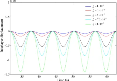
Time histories of interlayer displacements for upper and lower layers of layered beam have been illustrated in Figs. 8 and 9, for different values of exciting force. As can be observed, top layer be-havior don’t change, however, for bottom layer, as the force amplitude becomes larger, single peak gradually splits into two peaks in per-period.
Figure 8 Interlayer displacement of upper layer for different values of exciting force
From the results of numerical simulation, in the vicinity of initial slip, it is found that the re-sponses of system seem to be extremely sensitive to the exciting force amplitude, as shown in the Fig. 10. When there is a little change in the force amplitude, the motion of layered beam will be transferred from quai-periodic to the chaotic response suddenly. Fig. 11 shows the Poincare sections for 800 seconds of simulation in this situation for q1−q1 and q2−q2 planes, respectively. The
points of Poincaré sections are obtained with respect to the period of kinematic excitation 2π/ω. It is obvious from this Fig. that system demonstrates the chaotic motions for distinct aforemen-tioned conditions.
Latin American Journal of Solids and Structures 10(2013) 1025 – 1042
(a)
(b)
Figure 10 Comparison of results before and just after initial slip for µ=0.1 a: lateral history b: lateral displacement phase plane
As the state of system becomes far from initial slip, indicated in Fig. 12, when the exciting am-plitude increases, nonlinear behavior of lateral and longitudinal motions become more regular than around the initial slip, especially for lateral vibration. However, the phase portrait in the longitudi-nal direction, as shown in Fig. 12b, exhibits less sensitivity to this change.
(a) (b)
Latin American Journal of Solids and Structures 10(2013) 1025 – 1042
(a) (b)
(c) (d)
Figure 12 Comparison of results far from initial slip for µ=0.2 lateral phase plane for a: f0=1×10 −2
b: f0=5×10⁻² and
longitudinal phase plane for c: f0=1×10 −2
d: f0=5×10⁻²
To study the effect of friction on the layered-beam dynamics, phase portraits in lateral direction for different values of friction coefficient are plotted in Fig. 13. As can be expected, the less coeffi-cient of friction causes the less time of sticking phase and more regular dynamic behavior. When the coefficient of friction becomes larger, the phase plane of motion seems to be more irregular and proceed to chaotic behavior.
(a) (b)
Latin American Journal of Solids and Structures 10(2013) 1025 – 1042
(c) (d)
Figure 13 (continued) Comparison of lateral phase plane for p*=1×10⁻⁶ and a: µ=0.01 b: µ=0.05 c: µ=0.1 d: µ=0.2
The effect of exciting frequency have been conducted in this research through varying the non-dimensional parameter r
t. Figs. 14a to 14d indicate that an increase in the parameter rt from 0.2 to 0.3 leads to a decrease in the uneven vibrational slip velocities at the interface, for studied values of dry friction coefficient. It is clear that the irregular fluctuating of interface slips in the phase space decreases by increasing the parameter r
t.
(a) (c)
(b) (d)
Figure 14 Effect of exciting frequency on interface slip at a: and b:r
Latin American Journal of Solids and Structures 10(2013) 1025 – 1042
Poincre sections of typical chaotic motions of layered structure for two different values of non-dimensional frequencies r
t =0.2 and rt =0.3 are plotted in Fig. 15. The Poincare sections are projected onto q1−q1, q2−q2 and q3−q3 planes. While it is difficult to recognize chaotic
behavior from the time history, Poincaré maps and Lyapunov exponents clearly show the chaotic nature of the response.
(a) (b)
(c) (d)
Figure 15 Poincare section of chaotic motions for r
t =0.2 a: q1−q1 plane b: q2−q2 plane and for rt =0.3 c: q1−q1 plane d: q3−q3 plan
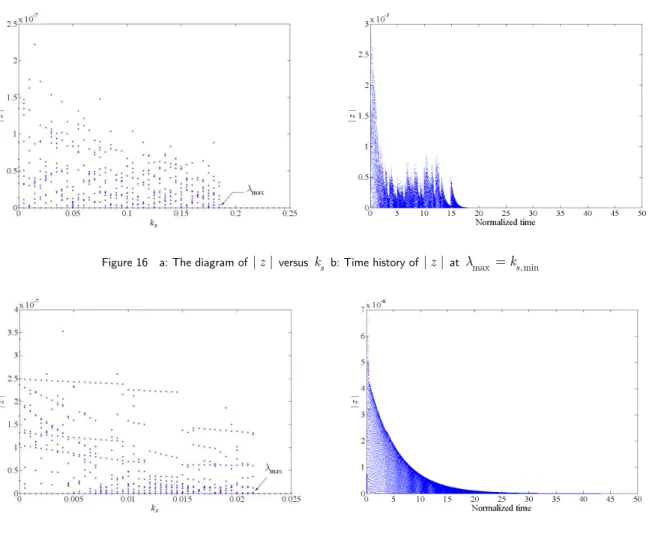
The largest Lyapunov exponent estimation is also used to identify the system dynamic behav-iors. For the calculation processes of the largest Lyapunov exponent, the algorithm introduced by Fu and Wang [20] have been employed. In order to find the smallest synchronization value (the largest Lyapunov exponent), bifurcation diagram of the disturbance value against the synchroniza-tion parameter, is constructed for investigated situasynchroniza-tion in Fig 11. In Fig. 16, the bifurcasynchroniza-tion dia-gram shows z = x−y versus coupling coefficient ks, so the searched value ks, min as a point on
the horizontal axis is obtained where z
approaches to zero. Therefore, the largest Lyapunov expo-nent is λ
max =ks, min =0.185 which implies that the system is evidently chaotic.
Similarly, the largest Lyapunov exponent has been calculated for the situation studied in Figs. 15a and 15b. From bifurcation diagram shown in Fig. 17, the largest Lyapunov exponent in this situation is λ
Latin American Journal of Solids and Structures 10(2013) 1025 – 1042 Figure 16 a: The diagram of |z | versus k
s b: Time history of |z |at λmax =ks, min
Figure 17 a: The diagram of |z | versus k
s b: Time history of |z |at λmax =ks, min
Latin American Journal of Solids and Structures 10(2013) 1025 – 1042
Figure 18 Comparison between interlayer displacements of top layer
Figure 19 Comparison between lateral displacement results
4 CONCLUDING REMARKS
Latin American Journal of Solids and Structures 10(2013) 1025 – 1042 Lyapunov exponent analysis for different values of system parameters. Finally, a comparative study with ANSYS is prepared to demonstrate the accuracy of the presented formulations.
References
[1] Goodman L.E., Klumpp J.H. Analysis of slip damping with reference to turbine blade vibration, Journal of Applied Mechanics, 23, 1956, pp. 421-429.
[2] Badrakhan F. Slip Damping in Vibrating Layered Beams and Leaf Springs: Energy Dissipated and Optimum Considerations, Journal of Sound and Vibration, 174(1), 1994, pp. 91-103.
[3] Damisa O., Olunloyo V.O.S., Osheku C.A., Oyediran A.A. Dynamic analysis of slip damping in clamped lay-ered beams with non-uniform pressure distribution at the interface, Journal of Sound and Vibration, 309, 2008, pp. 349-374.
[4] Olunloyo V.O.S., Damisa O., Osheku C.A., Oyediran A.A. Analysis of the effects of laminate depth and mate-rial properties on the damping associated with layered structures in a pressurized environment, Transactions of the Canadian Society for Mechanical Engineering, 34(2), 2010, pp. 165-196.
[5] Li Q., Li W. A contact finite element algorithm for the multileaf spring of vehicle suspension systems, Proceed-ings of the Institution of Mechanical Engineers, Part D: Journal of Automobile Engineering, 218, 2004, pp. 305-314. DOI: 10.1243/095440704322955821.
[6] Awrejcewicz, J., Krysko, A.V., Zhigalov, M.V., Saltykova, O.A., Krysko, V.A. Chaotic vibrations in flexible multi-layered Bernoulli-Euler and Timoshenko type beams, Latin American Journal of Solids and Structures, 5, 2008, 319-363.
[7] Awrejcewicz, J., Krysko, A.V., An iterative algorithm for solution of contact problems of beams, plates and shells, Mathematical Problems in Engineering, 2006, 1-13, DOI 10.1155/MPE/2006/71548.
[8] Awrejcewicz, J., Krysko, A.V., Ovsiannikova, O. Novel procedure to compute a contact zone magnitude of vibrations of two-layered uncoupled plates, Mathematical Problems in Engineering 2005:4 (2005) 425–435, DOI: 10.1155/MPE.2005.425.
[9] Krys’ko V.A., Koch M.I., Zhigalov M.V., Krys’ko A.V., Chaotic phase synchronization of vibrations of multi-layer beam structures, Journal of Applied Mechanics and Technical Physics, 53(3), 2012, pp. 451–459, DOI: 10.1134/S0021894412030182.
[10] Ibrahim R.A. Friction-induced vibration, chatter, squeal, and chaos, part II: dynamics and modeling, Appl. Mech. Rev. ASME, 47, 1994, pp. 227–253.
[11] Brockley C.A., Ko P.L. Quasi-harmonic friction-induced vibration, J. Lubr. Tech. Trans. ASME, 89, 1970, pp. 550–556.
[12] Kang J., Krousgrill C.M., Sadeghi F. Oscillation pattern of stick–slip vibrations, International Journal of Non-Linear Mechanics, 44, 2009, pp. 820-828.
Latin American Journal of Solids and Structures 10(2013) 1025 – 1042
[14] Stefanski A., Kapitaniak T., Using Chaos Synchronization to Estimate the Largest Lyapunov Exponent of Nonsmooth Systems, Discrete Dynamics in Nature and Society, 2000, 4(3), 207-215.
[15] Awrejcewicz J., Grzelczyk D., Pyryev Yu. A novel dry friction modeling and its impact on differential equa-tions computation and Lyapunov exponents estimation, Journal of Vibroengineering, 10(4), 2008.
[16] Licskó G., Csernák G. Chaos in a simply formulated dry-friction oscillator, Proceedings of 4th Chaotic Model-ing and Simulation International Conference, 31 May – 3 June 2011, Agios Nikolaos, Crete Greece.
[17] Wojewoda J., Stefanski A., Wiercigroch M., Kapitaniak T. Estimation of Lyapunov exponents for a system with sensitive friction model, Arch Appl Mech, 2009, 79, 667–677.
[18] Heuer R., Adam C. Piezoelectric vibrations of composite beams with interlayer slip, Acta Mechanica, 140, 2000, pp. 247-263.
[19] Han Q., Zheng X, Chaotic response of a large deflection beam and effect of the second order mode, European Journal of Mechanics A/Solids, 24, 2005, pp. 944–956.