RELIABILITY ANALYSIS OF TYPICAL COLD-FORMED STEEL BEAMS SECTIONS
Raylza Santos da Silva Campos
André Luis Riqueira Brandão
raylzacampos@gmail.com andreriqueira@unifei.edu.br Universidade Federal de Itajubá
Rua Irmã Ivone Drumond, 200, Distrito Industrial II, 35903-087, Minas Gerais, Itabira, Brazil
Marcílio Sousa da Rocha Freitas
marcilio@em.ufop.br
Programa de Pós-Graduação em Engenharia Civil, Universidade Federal de Ouro Preto, Campus Universitário Morro do Cruzeiro, 35400-000, Ouro Preto - MG, Brasil,
Abstract.This paper presents a reliability analysis of cold-formed steel beams, based on the FORM and MC simulation and using data obtained from experimental tests performed at the Johns Hopkins University, Baltimore (Schafer, 2003; 2006). This paper approached two sets of flexural tests, one referring to the failure by local buckling, and another for distortional buckling. A failure function is assembled to obtain, by taking into account the statistical parameters of the material (M), fabrication (F), and professional factors (P). The material and fabrication factors were taken from AISI standard. The professional factor was determined by comparing the tested failure loads and the predicted ultimate loads calculated from the selected design provisions. The goal of the paper is the assessment of reliability index for two nominal live-to-dead load ratios, as well as to compare the value found considering the load combinations for ultimate limit states.
1 INTRODUCTION
In the mid 1970s, there were significant changes in international construction standards, recommending probabilistic delineation in the design of structures. The reliability theory has been incorporated in the assessment of structural safety projects in construction and shipbuilding, becoming known from the 70s, as Structural Reliability (Ang and Cornell, 1974).
The reliability theory carries as fundamental role, in the construction branch of safety and performance analysis, a realistic description of a project template or structural analysis. The statistical nature of materials’ actions and properties has been the cause of study in different countries. Such study has shown that the uncertainty of the applied forces and structural resistance generate uncertainty in structural performance, such uncertainties can be analyzed through the reliability theory application. In this context, structural reliability presents itself as a valuable tool for the structure safety analysis providing a more accurate
measure of the degree of security, since this is based on determining failure probabilities (Pf)
or reliability indices ().
In building construction, cold-formed steel elements are mainly used as structural members, floors, walls, diaphragms and roofs. The main advantage is lightweight which can be translated in reduced costs by using less steel for structural elements. The most recent edition of the brazilian specificacion for the design of cold-formed steel structural members was published in 2010 (ABNT NBR 14762, 2010) and is mainly based in the AISI specification valuable at the time. This study uses experimental data from Yu e Schafer (2003, 2006), who tested cold-formed steel members subjected to bending moment. These members had lipped C- and Z-sections, and were conditioned to failure by local or distortional buckling. The comparison between experimental and theoretical results provided by Yu e Schafer (2003, 2006), defined as professional factor (model error), was used as a random variable in the structural reliability analysis of this work.
2 STRUCTURAL RELIABILITY
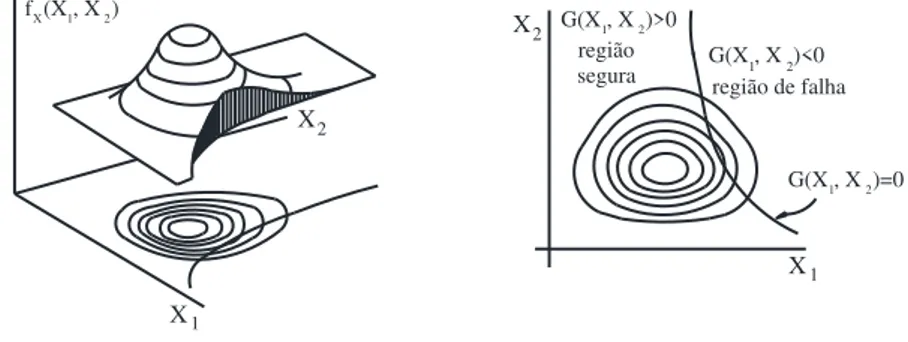
Structural reliability analysis is based on the existence of a failure function or limit state design G(X), wherein X=(X1, X2,..., Xn) represents the set of random variables involved in the analysis, in other words, all those with some statistical information regarding it. The failure function G(X) must be defined so that the limit G(X)=0 separates the failure domain (G(X)<0)
and the safety domain (G(X)>0) (Hsiao, 1989).
So structural reliability must seek the probability of failure events, i.e., what is the failure function probability of taking values belonging to the failure domain. This probability is known as failure probability and described by:
( )0
PG X
Knowing that fX(X) represents the joint probability density function (pdf) of all X variables involved in the analysis, failure probability can be described by the integral:
0 ) ( ) ( X X G Xf f dx
P (2)
Thus, reliability is defined as f
P
C1 (3) The integration of Eq. (2) can be illustrated by Fig. 1 for a case of two random variables. The figure illustrates the joint probability density function and its level curves projected on
) (X X
f surface on the X1X2 plan. All the points contained in the same contour curve have same value as fX(X), in other words, same probability density (Hsiao, 1989).
f (X , X )X 1 2
X1
X1
X2
X2
G(X , X )>0 1 2
G(X , X )<0 1 2
G(X , X )=0 1 2 região de falha região
segura
Figure 1. Failure probability integral in the basic variables space.
In structural analysis, it is possible to define the failure function G(X), as being:
Q R Z
G(X) (4)
where R e Q represent random variables of resistance and load effects, respectively.
It is assumed that the probability density function and cumulative density function of R and Q are known (Hsiao, 1989). Thereby, probabilities associated with the events can be defined by:
0 ) ( ) ( ) 0 ) ( ( ) ( X X X G Xf P R Q P G f dx
P (5)
Assuming that R and Q are statistically independent, the probability of failure can be represented as:
f r f qdrdq F q f qdq
Pf R( ) Q R Q (6)
The large number of random variables involved in many practical problems makes it quite difficult to obtain the joint probability density function and the integration of the equation is nearly always infeasible. Alternatively, the structural safety is measured as a function of the reliability index β, defined as the shortest distance from the origin of standardized or reduced variables space to failure surface (Cornell, 1969). The reliability index is undoubted important from the point of view of design safety because such index is a relative safety measure, i.e., when comparing two or more projects, the one that presents the biggest β is more reliable (AISI S100, 2007).
2.1 FORM method
FORM method is based on the transformation of basic variables X, whether or not correlated, in statistically independent standard variables U, called reduced variables, as well as the fault function that can be defined in the reduced variables space. There are several ways to turn the random variables X into random standard variables U and statistically independent. The methodology that uses structural reliability the most bases itself on the transformation of correlated standard variables into statistically independent standard variables. This transformation is known as Nataf transformation.
Another method step consists in the failure surface approximation G(U)=0, function defined in the reduced variables space, by a linear surface (first order of Taylor expansion) on the point with the shortest distance to the origin, identified by
* *
2 * 1
* , ,...,
n
U U U
U . This is
the design point in the reduced variables space, that is, the highest local density probability point. One of the most commonly used algorithms to obtain the design point is the one developed by Hasofer and Lind (1974) and improved by Rackwitz and Fiessier (1978). This algorithm is commonly referred to as HLRF.
The distance between design point and origin is called reliability index . Ergo, reliability index probability can be measured by vector
U
*length, i.e.,*
U
(7)where
.
represents magnitude of a vector. Being,a
U
*
(8)where a is the unit vector, perpendicular to failure surface, on the design point.
Ditlevsen e Madsen (1996) demonstrated, using standard distribution properties , that failure probability is given by:
f
P
(9)where (.) represents cumulative standard distribution.
2.2 FOSM method
through the average of random variables, using mean and variance, in other words second order statistical moments. Equations (10) and (11) of mean and standard deviation, respectively, were obtained assuming that random variable are independent among them and trucating Taylor expansion in linear terms.
) ,..., , ( 1 2 )
(X X X Xn
G G
(10)
n i i X X G X g 1 2 2 )( 1
(11)
Failure probability can be determined through Eq. (12).
g g f P
(12)
The relation g g is known as Cornell reliability index (1969).
2.3 Monte Carlo simulation (MCS)
From a set of n random variables X={x1,x2,...,xn}, these being individually characterized by
their marginal probability density function and their marginal cumulative distribution function FXi(xi), failure probability, associated with a limit state design G(X), which defines a failure
region, can be calculated by:
dx X f X G I dx X f P X G
f ( ) [ ( )] ( )
0 )
(
(13)
where fx(X) is the probability density function of random variables and I[g(X)] is a indicator function defined by:
( ) 0 0 ) ( 1 0 )] ( [ G X
X G se se X g
I (14)
Indicator function enables the calculation of integral from Eq. (13) on the entire domain. The average indicator function value represents this equation’s result. Therefore, failure probability can be estimated through Eq. (15).
)] ( [ 1 1 ^
nf j jf I G x
ns
P (15)
where ns is the number of simulations, xj is the j-th sample vector simulated containing n variables and [ ( )]
1
nf j j x GI represents the sum of simulation numbers ocurred in the failure region (nf). Hence, Eq. (15) can be rewritten as illustrated below:
ns nf Pf
^
(16)
ns P P
P
Var( f) f (1 f)
^ ^
^
(17)
Structures failure probability is generally low, order from 10-3 to 10-5, and as its variance
is expressed inversely proportional to the total number of simulations (ns), ns value must be
elevated in order to obtain acceptable approximations of Pf (Pulido et al., 1992).
Once the estimated failure probability is calculated by simulation, using Eq. (16), β
reliability index is obtained by the expression:
)
1
(
^1
f
P
(18)where -1(.) is the inverse of cumulative standard probability density function.
3 BEAMS SUBMITTED TO BENDING MOMENT
NBR 14762 (2010), based on limit state design, establishes basic requirements that must be met in the design of cold-formed steel, made out of sheet metal or carbon strip steel or low-alloy steel, intended for building structures. This standard foresees three design methods: effective width method (EWM), effective section method (ESM) and direct strength method (DSM). In this paper, it was adopted the DSM, which considers the geometric properties of the gross section and overall analysis of elastic stability, which identifies, for this case, all modes of buckling and their critical efforts.
In case of steel bar submitted to bending moment, basic conditions are that solicited bending moment (MSd) must be smaller than or equal to resistance bending moment (MRd).
Therefore resistance bending moment is calculated according to Eq. (19) at the beginning of effective section flow, and according to Eq. (20) due to lateral torsional buckling (FLT):
y ef Rd
f W
M (19)
FLT cef y Rd
f W
M , (20)
where, Wef effective section elastic resistance modulus in relation to extreme fiber that
reaches flow, Wc,ef effective section elastic resistance modulus in relation to external
compressed fiber and is resistance factor. Cross section geometrical properties (Wef and
Wc,ef) can be calculated based on EWM or ESM. Formulation of DSM considers strength
elastic modulus of gross section (W) modulus in relation to extreme fiber that reaches flow (AISI, 2007; NBR 14762, 2010).
AISI (2007) specifies a resistance factor = 0.90 for LRFD (Load and Resistance Factor
Design). ABNT NBR 14762 (2010) uses equivalent value to AISI for LRFD, in other words, resistance factor = 1.10 ( is the inverse of ). In case of LSD (Limit States Design),
resistance factor specified by american standard is = 0.85.
3.1 Direct strength method
finite element method or finite strip method (FSM), in order to perform a linear stability analysis of open sections and thin-walled profiles. FSM employs strip elements transversely along longitudinal direction, being the length of these strips assumed to be equal to the length of a half wave of buckling. It is noteworthy that the FSM model used results in fewer degrees of freedom than a finite element mesh, which greatly facilitates the entry and processing of data.
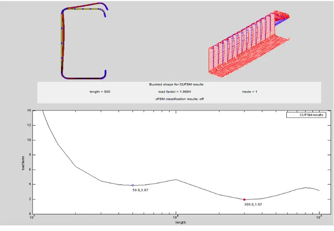
CUFSM (Cornell University Finite Strip Method) program developed by Schafer (2001) is appropriated to cold-formed steel design analysis. Such software is available for free on Cornell University website, and employs the semi-analytical finite strip method to provide solutions for the cross-section stability of cold-formed steel members. Figure 2 illustrates CUFSM program use, for one of the member subject to bending, experimental program Yu and Schafer (2003) constant. It can be seen that the first branch of the graph corresponds to the local buckling plate and the second branch corresponds to distortional mode. Third brand corresponds to global buckling (lateral torsional buckling). Critical values (minimum values) of local elastic buckling bending moments and distortional are employed in obtaining nominal
bending moment strength (MRk)
4 PROCEDURES FOR RELIABILITY ANALYSIS
4.1 Resistance and load statistics
Ravindra and Galambos (1978) describe resistance of a structural element as shown in Eq. (21):
PMF R
R n (21)
where Rn is strutuctural element nominal resistance, P is professional factor (model error), M is material factor and F is fabrication factor. Considered dimensionless random variables, P, M and F reflect model, material and geometric properties uncertainties, respectively (Hsiao, 1989).
Assuming that P, M and F variables are uncorrelated and using first order probabilistic theory, resistance mean (Rm) can be obtained through Eq. (22).
) ( m m m n
m R P M F
R (22)
where,
Pm é is ratio mean between experimental and theoretical resistance, calculated according to a given model, using material and geometric properties;
Mm is the ratio mean between material mechanical resistance obtained from testing and specified minimum value;
Fm is ratio mean between geometric property measured and specified value (nominal). The variation coefficient of variable R is equal to
2 2 2
F M P
R V V V
V (23)
where,
VP is measurement error model variation coefficient; VM is material factor variation coefficient;
VF is manufacturing factor variation coefficient.
Hence, Pm, Mm , Fm, VP, VM and VF needed statistical data to determine resistance statistical properties Rm e VR. Mean and standard deviation from M and F random variables can be obtained from NBR 14762 (2010) and AISI (2007) standards. Probability distribution functions were assumed to be lognormal (LN). Statistical data obtainment of random variable P will be presented in subsection 5.1.
Table 1. Random variables statistics of dead and live loads (Galambos et al., 1982)
4.2 Failure function domain
Equation (24) correlates nominal resistance (Rn) with nominal loads following limit state
design used by ABNT NBR 14762 (2010) standard.
) ( D n L n
n c D L
R
(24)
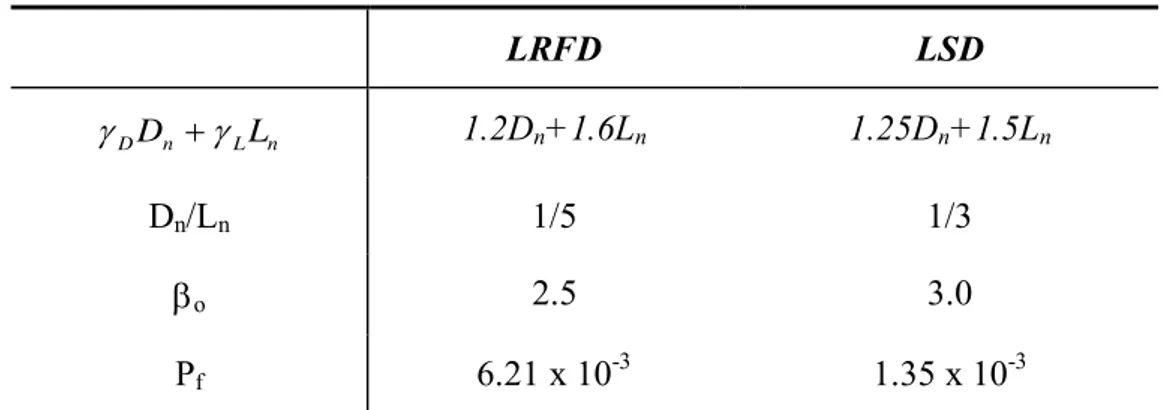
where is resistance factor, Dn and Dn are the nominal values of the dead and live load, D and L are dead and live load factors, respectively, and c is deterministic coefficient that relates load intensities to the loads effects. AISI (2007) calibration data can be observed in Table 2, which are parameters used in reliability analysis. LSD (Limit States Design) with
load combination 1.25Dn+1.5Ln is used in both brazilian and american standard. Brandão and Freitas (2013) considered a cross between load combinations and nominal dead-to-live load ratio (Dn/Ln) by inexistence, in NBR 14762 (2010), of specific procedures definition and specific reliability analysis parameters.
Table 2. Calibration data (AISI-S100, 2007).
Equation (25) represents failure function, in which R, D and L variables were remade based on their nominal values, by using limit state design defined according to Eq. (24), nominal resistance and Dn/Ln ratio. It is noteworthy that FORM and MCS reliability methods use probability distribution functions in addition to mean and standard deviation (Brandão and Freitas, 2015).
) ( (.) R c D L
G (25)
Type of load Mean
Value
Coefficient
of Variation
Type of
Distribution (pdf)
Dead load Dm = 1.05Dn VD = 0.10 Normal
Live load Lm = Ln VL = 0.25 Extreme Type I
LRFD LSD
n L n DD L
1.2Dn+1.6Ln 1.25Dn+1.5Ln
Dn/Ln 1/5 1/3
o 2.5 3.0
5 RESULTS
5.1 Resistance and load statistics
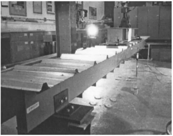
The experiment conducted by Yu and Schafer (2003, 2006), who tested cold-formed steel members subjected to bending moment, was specifically developed to enable local or distortional buckling occurrence. In Yu and Schafer (2003), a trapezoidal tile panel connected to the tested beams’ upper flange restricted global and distortional buckling (Fig. 3). It is noteworthy that theoretical analysis pointed out to distortional buckling, if not considered the lock imposed by placing the tile panel. In the experiment conducted by Yu and Schafer (2006), the objective was to study beams subjected to distortional buckling. In this study were considered Yu and Schafer (2003, 2006) data with lipped C- and Z-sections.
Measurement error model was calculated by Yu e Schafer (2003, 2006), from the ratio
between experimental resistance bending moment (Mtest) and theoretical resistance bending
moment, to each specimen. Theoretical resistance bending moment refer to resistance bending
moment characteristic value associated with local buckling (MRl) or distortional buckling
(MRdist).
Table 3 presents Yu e Schafer (2003, 2006) test data, organized for this study’s reliability analysis. Each data group presented in Table 3 was analyzed through Minitab 16 computer program in order to obtain statistical parameters of measurement model error random variable (P). Thus, it was feasible to describe this variable through mean (Pm), variation coefficient
(VP) and probability distribution function (pdf) that better adjusted to data set.
Table 3. Experimental groups. Source: Yu and Schafer (2003, 2006)
5.2 Reliability index calculation
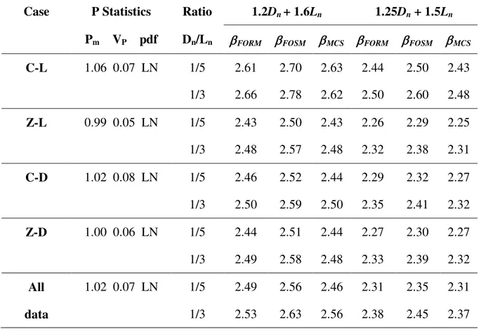
Reliability indices , presented in Table 4, were obtained by using reliability methods FORM, FOSM and MCS, with 100,000 iterations, to two load combinations and two relations Dn/Ln.
Table 4. Reliability indices obtained by section type and failure mode.
Nomenclature Failure mode Number
of tests
VP Pm Type of
Distribution (pdf)
C-L Local 30 0.05 0.99 Lognormal
C-L Local 20 0.07 1.06 Lognormal
C-D Distortional 18 0.08 1.02 Lognormal
C-D Distortional 16 0.06 1.00 Lognormal
All data Local and
Distortional
84 0.07 1.02 Lognormal
Case P Statistics Ratio 1.2Dn+ 1.6Ln 1.25Dn + 1.5Ln
Pm VP pdf Dn/Ln FORM FOSM MCS FORM FOSM MCS
C-L 1.06 0.07 LN 1/5 2.61 2.70 2.63 2.44 2.50 2.43
1/3 2.66 2.78 2.62 2.50 2.60 2.48
Z-L 0.99 0.05 LN 1/5 2.43 2.50 2.43 2.26 2.29 2.25
1/3 2.48 2.57 2.48 2.32 2.38 2.31
C-D 1.02 0.08 LN 1/5 2.46 2.52 2.44 2.29 2.32 2.27
1/3 2.50 2.59 2.50 2.35 2.41 2.32
Z-D 1.00 0.06 LN 1/5 2.44 2.51 2.44 2.27 2.30 2.27
1/3 2.49 2.58 2.48 2.33 2.39 2.32
Results obtainted, via FORM method, compared to the ones by MCS confirm analytical method accuracy for the performance function used in this work. Despite FOSM method’s simplicity and reduced accuracy, it proceeded with this analysis for comparative purposes, since the calibration coefficients of the American standard AISI (2007) were calibrated with such methodology. With American standard calibration data (combination 1.2Dn+ 1.6Ln and ratio Dn/Ln of 1/5), reliability indices were always higher than the target reliability index (o=2.5). American standard presents certain conservatism since the coefficient considering dead load Dn is inferior and the coefficient considering live load Ln is superior when compared to the value adopted by Brazilian standard.
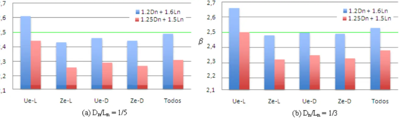
Figure 4. Comparison of reliability indices obtained from FORM method to each load combination.
Figue 4 shows a comparison between reliability indices obtained by FORM method according to load combinations and Dn/Ln ratio. It has been verified that results from Brazilian standard combination 1.25Dn + 1.5Ln are not satisfactory when compared to target reliability index of 2.5, with exception of C-L case (lipped channel section submitted to local instability).
6 CONCLUSIONS
It was presented in this paper a procedure for analysis of cold-formed steel design submitted to bending moment. Direct strength method (MRD) was used for analysis, in order to obtain bending moment resistance capacity, of sections defined from experimental data set.
It was verified that in the gravitational load combination analysis from Brazilian standard NBR 14762 (2010), reliability indices demonstrated small deviation in relation to target
reliability index (o=2.5). Using load combination from American standard AISI S100 (2007)
for LRFD, reliability indices were greater than the target reliability index. Despite design criteria similarity for bending defined by Brazilian and American standards, it can be said that they do not have the same safety level due to different load combinations. American model was more conservative, according to values used as load weighting coefficients.
Therefore, it is suggested to review standards committees, a clear definition of target reliability indices (o) and of nominal load ratio (Dn/Ln), in order to verify resistance factor
ACKNOWLEDGEMENTS
The authors thank CNPq, FAPEMIG and Unifei for sponsoring this study.
REFERENCES
ABNT NBR 14762, 2010. Dimensionamento De Estruturas De Aço Constituídas Por Perfis Formados A Frio. Rio de Janeiro.
AISI S100, 2007. Specification For The Design Of Cold-Formed Steel Structural Members.
Alves, A. R.; Brandão, A. L. R.; Freitas, M. S. R., 2015. Confiabilidade De Barras Em Perfis
Formados A Frio Submetidos À Força Axial De Compressão Via Método Form. Iberian
Latin-American Congress On Computational Methods In Engineering. Abmec, Rio de
Janeiro, Rio de Janeiro, Brasil.
Ang, A. H-A. E Cornell, C. A., 1974. Reliability Bases Of Structural Safety And Design.
Journal Of The Structural Division, ASCE. Vol. 100, Número 9, Pp. 1755-1769.
Ang, A. H-S. E Tang, W. H., 1990. Probability Concepts In Engineering Planning And
Design – Decision, Risk and Reliability. Vol. Ii, John Wiley & Sons, 562p, EUA.
Brandão, A. L. R.; Freitas, M .S. R., 2013. Calibração De Coeficiente De Ponderação Da
Resistência Em Ligações Soldadas De Perfis Formados A Frio. Iberian Latin-American
Congress On Computational Methods In Engineering. Abmec, Pirenópolis, Goiás, Brasil.
Cornell, A. C., 1969. A probability based structural code. ACI Journal, vol. 66, 12, 974-985.
Freitas, M. S. R., 1998. Combinação de modelos probabilísticos e possibilísticos para a
análise de confiabilidade estrutural. Tese de Doutorado, Universidade Federal do Rio de
Janeiro (COPPE).
Galambos, T.V., Ellingwood, B., MACGREGOR, J.G., Cornell, C.A., 1982. Probability based load criteria: assessment of current design practice. Journal of the Structural
Division,Vol. 108, n. ST5, pp. 959-977.
Javaroni, C.E., 2015. Estruturas De Aço: Dimensionamento De Perfis Formados A Frio. 1a
Ed. Elsevier Editora Ltda.
Kiureghian, A.D., 2008. Analysis Of Structural Reliability Under Parameter Uncertainties.
Probabilistic Engineering Mechanics, Vol. 23, No. 4, Pp. 351-358.
Pulido, J. E., Jacobs, T. L., Prates de Lima, E. C., 1992. Structural reliability using Monte
arlo simulation with variance reduction techniques on elastic-plastic structures. Computer and
Structures, p. 419-430.
Ravindra, M. K.; Galambos, T. V., 1978. Load And Resistance Factor Design For Steel.
Journal of the Structural Divison, 104, ST9, 1337-1353.Schafer, B. W. (2001).
Cufsm 2.5 Software. User Manual And Tutorials. Disponível No Site
www.ce.jhu.edu/bschafer/cufsm. Acesso em 15 de março de 2016.
Yu, C., Schafer, B. W., 2003. Local Buckling Tests On Cold-Formed Steel Beams. In:
Journal Of Structural Engineering. 10.1061/(ASCE)0733-9445(2003)129:12(1596), 1596
1606.