Abstract
Interface strength is considered as one of the most influential factors in the long-term durability of the replaced joint in cement-ed total hip replacement. Several researchers have suggestcement-ed that the damage initiation in a replaced joint is a mechanical phenom-enon primarily taking place in the vicinity of cement-prosthesis interface. In this study, the fracture behavior of a crack at the interface of cement-prosthesis was investigated both experimental-ly and theoreticalexperimental-ly under static loading conditions. The finite element method, and then the maximum tangential stress (MTS) and the generalized MTS (GMTS) criteria were used for theoreti-cal study of interface fracture. Some experiments were also carried out to investigate the effect of cement mixing methods (hand mixing and vacuum mixing) on crack growth pattern. The results showed that the vacuum-mixed cement led to self-similar crack growth along the cement-prosthesis interface, while the crack kinked into the cement in the samples prepared by hand-mixed cement. Then some experiments were performed to verify the theoretical results obtained for mixed mode fracture angles in the samples prepared by hand-mixed cement. The sandwich Brazilian disk model was used in both finite element and experimental ap-proaches to simulate the cement-prosthesis interface. The experi-mental results were found to be in good agreement with those predicted by the GMTS criterion.
Keywords
Fracture mechanics; finite element stress analysis; mechanical properties of adhesives; bone cement
.
Investigation of Fracture in an Interface Crack Between Bone
Cement and Stainless Steel
1 INTRODUCTION
In the early 1960s, Sir John Charnley introduced a new method, using acrylic bone cement (PolyMethylMethAcrylate, PMMA), to fill the space between the prosthetic stem and bone, which has been a brilliant practice for hip joint replacement (Ohashi, 2000). In a replaced joint, multiple
M. Choupania
M.R. Ayatollahia*
M. Mallakzadehb
aFatigue and Fracture Laboratory,
Cen-ter of Excellence in Experimental Solid Mechanics and Dynamics, School of Me-chanical Engineering, Iran University of Science and Technology,
Narmak, Tehran, 16846, Iran.
Tel.: +98 21 7724 0201; fax: +98 21 7724 0488
bSchool of Mechanical Engineering, Iran
University of Science and Technology, Narmak, Tehran, 16846, Iran, e-mail: [email protected]
Corresponding author: *[email protected]
http://dx.doi.org/10.1590/1679-78251142
Latin A m erican Journal of Solids and Structures 12 (2015) 446-460
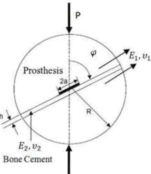
biological and mechanical factors may cause the joint damage, while the preliminary defects after surgery are suggested to be mainly mechanical (Tong et al., 2007). Researchers have considered different mechanical factors that might directly influence the prosthesis failure initiation including the cement strength (Knets et al., 2007), the strength of bone-cement interface (Mann et al., 2001), the strength of cement-prosthesis interface (Ohashi, 2000), the thickness of cement mantle (Wang and Agrawal, 2000), the elastic modulus incompatibility at the cement interface and the cement porosity (Dunne and Orr, 2001). There are some evidence indicating the separation of prosthesis from cement in samples used for more than four years, even when the bone-cement interface sur-vives (Ohashi, 2000). These factors demonstrate the significance of investigating the cement-prosthesis connection. In this study, the sandwich Brazilian disk model shown in Figure 1 has been used to analyze the cement-prosthesis separation process. The Brazilian disk sample is a widely used model providing the loading mode conditions from mode I to mode II as a function of loading angle
. The sandwich Brazilian disk sample can be employed to reflect the loading nature at the ce-ment-prosthesis interface due to the fact that the prosthesis, in a general case, is subjected to a combination of compression and shear, which the Brazilian disk is capable of creating (Tong et al., 2007; Yuuki et al., 1994).
As shown in Figure 1, in the present study the prosthesis and the bone cement are indicated by material numbers 1 and 2 respectively and a central crack of length 2a is embedded in the interface between the two materials. By this configuration, under the compression load P, various combina-tions of mode I and mode II can be provided in different loading angles by rotating the disk. Finite element analysis was conducted to compute the stress intensity factors and the T-stress. Po-rosity, leading to accelerated micro-crack formations, weakens the bone cement. Therefore, the mix-ing method for raw materials can play a key role in the bone cement quality. The effects of hand-mixing and vacuum-hand-mixing of bone cement on the bond strength of cement-prosthesis connection was also investigated experimentally. Subsequently, to verify the fracture angles predicted from finite element analysis, a number of experiments were carried out for loading angles ranging from 7.5° to 60°.
Latin A m erican Journal of Solids and Structures 12 (2015) 446-460 2 STRESS FIELD NEAR THE CRACK TIP AT THE INTERFACE OF TWO MATERIALS
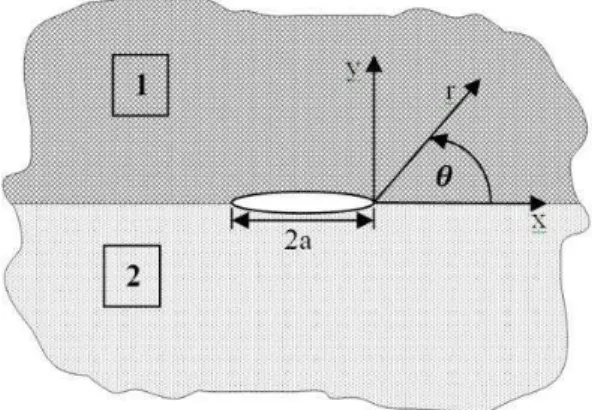
Figure 2 shows a crack of length 2a in the interface of two materials with the elastic constants E1,
1 for the material 1 and E2, 2 for the material 2. x y, and r, are the Cartesian and polar coordinate systems, respectively.
Figure 2: The area nearby the interface of two materials.
The elastic stresses for material 1 have been given in (Ravichandran and Ramesh, 2005) in terms of stress intensity factors KI and KII. If the first non-singular term of stress, often called the T-Stress, is also taken into account, the elastic stresses can be written in the polar coordinates as:
( ) ( )
1
( )
3
3 cos ln 2 sin( ) cos ln sin( ) sin ln cos ln
2 2 2 2
2 2
3 sin ln
2 2 2 I rr II k
e r r r e r
r k e r r ( ) 1 3
2 sin( ) cos ln sin( ) cos ln sin ln
2 2 2
(1 cos(2 ))
r r e r
TD (1) ( ) ( ) 1 ( ) 3
cos ln 2 sin( ) cos ln sin( ) sin ln cos ln
2 2 2 2
2 2 sin ln 2 2 2 I II k
e r r r e r
r k e r r ( ) 1 3
2 sin( ) sin ln sin( ) sin ln sin ln
2 2 2
(1 cos(2 ))
r r e r
TD (2) ( ) ( ) 1 ( ) 3
sin ln 2 sin( ) sin ln sin( ) cos ln sin ln
2 2 2 2
2 2 cos ln 2 2 2 I r II k
e r r r e r
r k e r r ( ) 1 3
2 sin( ) cos ln sin( ) sin ln cos ln
2 2 2
( sin(2 ))
r r e r
TD
(3)
The bi-material constant ϵ in these equations can be expressed in terms of the elastic constants of materials 1 and 2 as (Ravichandran and Ramesh, 2005):
1 1 2
2 2 1
1 1
ln
2 1
k
k (4)
Latin A m erican Journal of Solids and Structures 12 (2015) 446-460
where 1 and 2 are shear moduli and k is expressed as:
3 4 Plane Strain
3 1, 2
Plane Stress 1
j j j
j
k j (5)
While equations (1–3) present the stress field for material 1, similar equations can be obtained for material 2 by converting e to e and e to e . Moreover, the T-stress in material 2
can be found by replacing D1 by D2 as followed:
2 1
1 2
1 2 1 2
1
( 1,2), ,
i i
i
k c c
c i D D
c c c c (6)
If the crack parameters KI, KII and T-stress are determined, the stress field in the vicinity of crack tip can be identified.
3 FINITE ELEMENT ANALYSIS
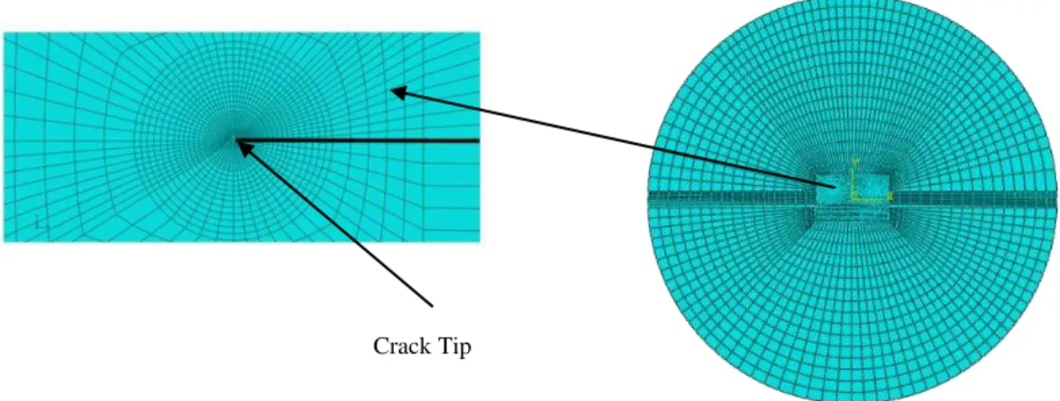
In this study, the finite element approach was employed to obtain the elastic stresses for a crack embedded between two dissimilar materials in a sandwich Brazilian disk and then, to calculate the stress intensity factors and the T-stress. Isoparametric 8-node plane strain elements were used for finite element simulation (see Figure 3).
Figure 3: The mesh pattern for the simulated sandwich Brazilian disk
.
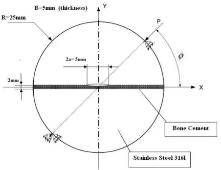
Figure 4 illustrates the dimensions of sandwich Brazilian disk used for finite element modeling and also later for the experiments. The material properties considered for the bone cement and the stainless steel are given in Table 1. Figure 4 also shows the loading and boundary conditions of the disk specimen. Finite element modeling was performed for different loading angles of 7.5o, 15o, 20o, 30o, 40o, 50o, and 60o.
Latin A m erican Journal of Solids and Structures 12 (2015) 446-460 Figure 4: Dimensions of the sandwich Brazilian disk specimen.
ν E(GPa)
Materials
0.3 193
Stainless Steel (316L)
0.3 2.4
Bone Cement (CEMEX RX)
Table 1: The elastic constants of bone cement and stainless steel.
After obtaining the near-crack tip stresses from the finite element analysis a numerical technique called the Finite Element Over-Deterministic Method (FEODM) were employed to calculate SIFs and the T-stress (Ayatollahi and Nejati, 2011). This method is based on the exploiting a large number of data to find a small number of unknowns. Accordingly, applying the stress equations (1– 3) to numerous numbers of nodes in the vicinity of the crack tip, the three unknowns KI, KII and
T are obtained by solving a system of linear equations. More details about FEODM can be found
in (Ayatollahi and Nejati, 2011).
The stress intensity factors KI, KII and the T-stress calculated for the interface crack were then normalized according to Equation (7):
*, * ( , )
( ) j j
P P a
T T K k j I II
R B RB (7)
where P, R, B, k*j and T*are the applied load, the disk radius, the disk thickness, the normalized
SIFs, and the normalized T-stress, respectively. Table 2 shows the numerical values of * I
k , kII* and *
T for different loading angles . It should be noted that finite element analyses were performed
Latin A m erican Journal of Solids and Structures 12 (2015) 446-460 Loading angle
(deg)
* I
k kII* T*
7.5 0.5909 -0.3800 -19.9687
15 0.5385 -0.4697 -20.7463
20 0.4963 -0.5185 -20.8523
30 0.3873 -0.5984 -20.3222
40 0.2617 -0.6522 -18.8378
50 0.1376 -0.6768 -16.7525
Table 2: Finite element results for * I k , *
II
k , T*for different loading angles .
4 FRACTURE ANALYSIS
Having calculated the stress intensity factors and the T-stress and their corresponding normalized values, the angle of fracture initiation in bone cement can be estimated by applying appropriate criteria. In this section, two fracture criteria are employed for estimating the angle of fracture initia-tion in the sandwich Brazilian disk specimen for different loading angles .
As shown in Figure 5, an interface crack may extend according to different possible paths under combined mode I/II loading (Chandra Kishen and Darunkumar Singh, 2001):
a. Crack may grow along the interface (case A).
b. Crack may branch off into each of the two materials (cases B and C).
c. Crack may both grow along the interface and branch off to each of the two materials, sim-ultaneously (cases D and E).
Latin A m erican Journal of Solids and Structures 12 (2015) 446-460
According to (Chandra Kishen and Darunkumar Singh, 2001), a crack often branches off into a material outside the interface, if the interface connection is strong enough and the crack plane is exposed to shear stresses as well.
Maximum tangential stress (MTS) (Erdogan and Sih, 1963) and generalized maximum tangen-tial stress (GMTS) (Smith et al., 2001) criteria have been developed in order to investigate brittle fracture in linear elastic materials under combined tensile and shear loading. According to these criteria, the crack will grow through a direction in which the tangential stress reaches its maximum. In the MTS criterion, only the singular term of stress (i.e. the term corresponding to KI and KII) is considered. While in GMTS, in addition to KI and KII, the non-singular term T is taken into account in the equation of tangential stress in the vicinity of the crack tip. To calculate the fracture angle, SIFs and T-stress should be substituted into equation (2) and then, equation (8) should be solved to find the angle of maximum tangential stress.
0 (8)
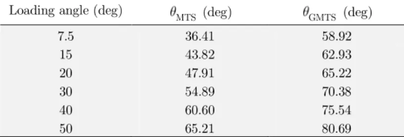
It is assumed that the strength of the cement-prosthesis joint is high enough such that the crack kinks out of the interface within the weaker material (i.e. the bone cement) according to case C in Figure 5. This is in agreement with the experimental observations, as described later. Therefore, the angle of maximum tangential stress around the crack tip was extracted just within the bone ce-ment. Table 3 shows the fracture initiation angles calculated according to the MTS and GMTS criteria, i.e. MTS and GMTS.
Loading angle (deg) MTS (deg) GMTS (deg)
7.5 36.41 58.92
15 43.82 62.93
20 47.91 65.22
30 54.89 70.38
40 60.60 75.54
50 65.21 80.69
Table 3: Fracture initiation angles predicted using the MTS and GMTS criteria.
One should note that for an interface crack, the values of T-stress above and below the interface are not the same (Jian-Jun and Yi-Heng, 2000). Consequently, the normalized T-stresses presented in Table 2 are related to the bone cement material in the sandwich Brazilian disk specimen.
Table 3 reveals that the fracture angles obtained from the MTS criterion is significantly different from those calculated from the GMTS criterion. This finding highlights the important role of T-stress in the fracture behavior of stainless steel-bone cement interface cracks. In the following, the credibility of the theoretical results will be investigated via experimental studies.
5 EXPERIMENTS
Latin A m erican Journal of Solids and Structures 12 (2015) 446-460
the first stage, some experiments were carried out to study the influence of cement mixing method upon the test results. Cement vacuum mixing is utilized as a widely acceptable technique to make the cement homogenous, to decrease porosity, and to increase the cement strength. This method can improve the cement properties by extracting the MMA vapor resulting from polymerization in PMMA combination step, evacuating the cement from air and averting bubble formation inside the sample. However, the effect of vacuum mixing on the adhesion between the bone cement and the prosthesis is not clear. When two materials are brought in contact, the proper adhesion between them is very important and it is necessary to use appropriate ways to attain the highest bond strength. Therefore, the quality of the interface is significantly influenced by the properties of the adhesive and the substrate (Baldan, 2012). As a result, the fracture tests were first performed on the sandwich Brazilian disk specimens, its adhesive prepared by several mixing methods in order to find the suitable option for the subsequent experiments. The most appropriate method to mix the cement regarding the strength investigation at the cement-prosthesis interface is the one which pro-vides a complete connection between the cement and the prosthesis so that the crack, under load-ing, kinks and enters the cement. Consequently, such a connection endures a higher fracture load.
5.1 Materials and sample preparation
Bone cement was purchased from Cemex RX Company (Tecres, Verona, Italy). To mix bone ce-ment, three different methods including hand mixing, vacuum after hand mixing (using vacuum chamber) and simultaneous vacuum and mixing (or vacuum mixing) were utilized. More details on these mixing methods are given below.
5.1.1 Hand Mixing (HM)
After blending with the corresponding monomer (according to the instruction), the bone cement was mixed in a container with the frequency of 1 Hz for one minute and then, through a syringe was injected into the space between the two half-disks held inside a fixture.
5.1.2 Vacuum after Hand Mixing (VAHM)
In this method, a vacuum chamber with the pressure of 140 Mbar was employed (Dunne and Orr, 2001). First, the cement powder and the liquid component were mixed by hand in a container. Then, the mixture was exposed to the vacuum conditions for about 10 seconds and finally was in-jected in the space described earlier. However the mixture cannot be kept inside the vacuum cham-ber for a longer time otherwise it hardens and its viscosity increases. One should note that, in this method, it is not possible to decrease the amount of vapors resulting from the polymerization pro-cedure at the early moments since the mixture is mixed outside the vacuum machine
.
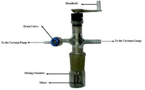
5.1.3 Vacuum Mixing (VM)
Latin A m erican Journal of Solids and Structures 12 (2015) 446-460
commercial VM machines such that the cement powder and the liquid component were blended in 0.7bar vacuum for 15 seconds. Then, after mixing for 30 seconds, the mixture was left at the same situation for 15 seconds (Mau et al., 2004).
Figure 6: The utilized vacuum mixing machine.
After preparation, the bone cement was injected through a syringe into the space between the two metal half-disks.
The half-disks were produced from stainless steel (316L) and the necessary surface preparation was performed on the straight edge of each half-disk. The preparation procedure consists of these steps: the half-disk edges were first degreased with soap and hot water, and then were polished by using a 120 grit emery paper, and the surfaces were finally degreased again with acetone. The crack was created by sticking a 50 µm thick (Tong et al., 2007 and Yuuki et al., 1994) and 5 mm wide scotch tape to the center of one of the half-disks. In this way, an artificial separation between bone cement and one of the metallic half-disks was created in order to play the role of a crack.
5.2 Experiment procedure
Twenty four hours after connecting the two half-disks, the sandwich samples were subjected to compression by a universal machine with a loading rate of 1mm/min as depicted in Figure 4. To assess the impact of production method upon the crack growth pattern, the samples prepared by different methods of cement mixing were initially tested at the arbitrary loading angle of 20°. Ac-cording to the finite element results, the values of *
I
k and kII* are almost equal for this loading angle and neither of the loading modes is dominant. The experiments, for this loading angle, were repeat-ed for at least 5 samples
.
5.3 Experimental results
measur-Latin A m erican Journal of Solids and Structures 12 (2015) 446-460
able. In contrast, for vacuum mixed cements the crack in all samples grew at the interface of ce-ment and prosthesis, indicating the poor connection at the interface. The fracture loads obtained for the samples prepared by the two vacuum mixing methods can be compared with those of the sam-ples prepared by hand mixing. Further details will be presented in the following section.
5.3.1 Fracture load analysis
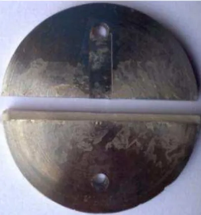
The experimental results showed that for all samples prepared by vacuum mixing method, fracture occurred at the cement-prosthesis interface and the crack did not kink into the cement. Figure 7 displays a fractured sample prepared by vacuum-mixed cement and also the crack growth at the interface.
Figure 7: The crack extension at the interface of cement and disk.
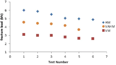
Regardless of the path along which the crack grows, one can obtain an estimation of the sample strength in each case by comparing the fracture load for different mixing methods. Figure 8 shows the fracture loads obtained for the samples containing the cements prepared by hand and vacuum mixing methods. The average fracture loads have also been given in Table 4. It is seen that the fracture load in samples prepared by vacuum-mixed cement is notably lower load than that of the samples prepared by hand-mixed cement. Therefore, the bond strength of the prosthesis and cement connection prepared by hand mixing is higher than that prepared by vacuum mixing. Meanwhile, within the vacuum mixed cements, the bond strength in the VAHM method is higher than in the VM method. One can suggest that although in the VM method, the cement strength itself is very good, its bonding method to the stainless steel prosthesis should be improved in order to achieve the bond strength desired for clinical applications
.
Mixing method Average fracture load (N)
HM 5384.95
VAHM 4245.28
VM 2851.23
Latin A m erican Journal of Solids and Structures 12 (2015) 446-460 Figure 8: The fracture load variation for the samples prepared by hand mixing (HM), vacuum after hand mixing
(VAHM) and vacuum mixing (VM) at the loading angle of 20°.
5.3.2 Fracture angle analysis
The experimental results obtained for different methods of cement mixing at the sample loading angle of 20° recommend the use of hand-mixed cements due to its better bond strength with the prosthesis. Hence, additional experiments were conducted at loading angles of 7.5°, 15°, 20°, 30°, 40°, 50° and 60°, similar to finite element analyses but only on samples containing hand-mixed cements. The angles of fracture initiation were determined from the experimental results for different loading angles.
Figure 9 displays a fractured sample and also the direction considered for measuring the crack kinking angle. As described earlier, for all samples containing hand-mixed cement, the interface crack kinked into the cement.
Latin A m erican Journal of Solids and Structures 12 (2015) 446-460
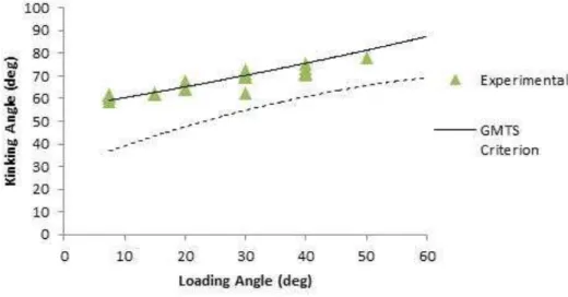
Table 5 shows the crack kinking angles versus the loading angles. Since 4 or 5 tests were per-formed for each loading angle, the illustrated kinking angles are the averages of the measured val-ues. It is worth mentioning that at the loading angle of 60°, no crack extension was observed. This can be due to the fact that none of the crack tips are under local tension at this loading angle. The experimental results obtained for the fracture angles together with the theoretical results predicted by the MTS and GMTS criteria are depicted in Figure 10. Very good agreement can be seen between the experimental results and theoretical values of fracture angles predicted by the GMTS criterion. It is worth noting that the predicted and measured fracture angles in Tables 3 and 5 are all positive. This is because the sign of *
II
k is negative in the test specimens, as shown in Ta-ble 2 (more details can be found in Smith et al. (2001)).
Loading angle (deg) Average kinking angle (deg)
7.5 60.43
15 62
20 65.5
30 69.1
40 72.28
Table 5: The average kinking angles versus the loading angles, obtained from samples prepared by hand-mixed cement
.
Figure 10: Theoretical and experimental results obtained for the fracture angle in the samples prepared by hand-mixed cement
.
Latin A m erican Journal of Solids and Structures 12 (2015) 446-460 Figure 11: The fracture loads versus loading angles in the samples prepared by hand-mixed cement
.
6 DISCUSSION
To simulate the effect of a pre-existing crack on the bond strength of the cement-prosthesis connec-tion in hip joint arthroplasty, a series of finite element analyses were conducted using sandwich Brazilian disk model. The stress intensity factors and the T-stress were calculated employing the "finite element over-deterministic" method. The results showed that increasing the loading angle, results in lowering KI and raising KII until the angle of 58.5° at which KII is almost zero and the specimen is subjected to pure mode II. The maximum tangential stress (MTS) and the generalized maximum tangential stress (GMTS) criteria were utilized to compute the angle of crack growth for several loading angles ranging from 7.5° to 60° and to study the effect of T-stress on the angle of crack kinking. To verify the theoretical estimates and also to determine the influence of vacuum in cement mixing on the experimental results, a few experiments were carried out on an interface crack between the stainless steel and the bone cement. First, some experiments were conducted in order to study the influence of the cement mixing method on the bond strength of the cement-prosthesis connection. As a factor accelerating micro-crack formation, porosity weakens the bone cement. Therefore, the way of mixing raw materials can play a decisive role in the quality of bone cement. According to the previous studies, the tensile and tribological properties of bone cement are considerably improved by vacuum mixing. For instance, Karimzadeh and Ayatollahi (2012) made use of the nano-indentation and nano-scratch testing and compared the properties of the bond ce-ments prepared by two methods of hand mixing and vacuum mixing. The materials and the proto-col used in (Karimzadeh and Ayatollahi, 2012) were the same as those introduced in the present study. Their results revealed that the elastic modulus and mode I fracture toughness for the cement samples mixed in vacuum were higher than those of the samples mixed by hand, due to a decline in the porosity volume of the samples prepared in vacuum (Karimzadeh and Ayatollahi, 2012). How-ever, the influence of the cement mixing method on the bond strength of cement-prosthesis connec-tion has not been contemplated in the past.
Latin A m erican Journal of Solids and Structures 12 (2015) 446-460
using a machine similar to the conventional VM machines. The experimental results were then compared to each other and also to those of hand mixing method. The results obtained from the tests on the vacuum-mixed cement samples indicated that the crack extended self-similarly along the interface between the bone cement and the steel. As a result, those samples fractured under a remarkably lower load than the hand-mixed cement samples. This issue indicates that although vacuum mixing improves the cement properties (lower porosity and higher strength), it has an ad-verse effect on the cement tendency to stick to stainless steel. Therefore, it would be very useful to find improved methods for bonding the vacuum-mixed cements to stainless steel in order to achieve superior mechanical properties both in the cement itself and in its connection to the prosthesis. The cracks in all hand-mixed cement samples kinked into the cement indicating a strong interface bond-ing which is likely due to lower viscosity of the hand-mixed cement.
The fracture load was higher in the hand-mixed cement cases because higher energy was re-quired for the extension of interface crack within the bone cement.
In the next stage, to validate the theoretical results obtained for fracture angles, a number of experiments were conducted at different loading angles on samples prepared by hand-mixed cement. It was observed that in almost all samples the crack kinked from its left hand side tip and entered the cement. The fracture angles were then measured and compared with those calculated by the MTS and GMTS criteria. The good agreement found between the results of GMTS criterion and the experiments indicates that the T-stress can be of a significant effect in interface cracks kinking into a brittle material. Indeed, by considering the T-stress in equation (2), a more precise model for the mathematical equation of stress is achieved in the vicinity of the crack which makes the GMTS criterion more accurate than the MTS criterion.
Since the strength of cement alone, the bond strength of bone-cement connection and the bond strength of cement-prosthesis are among the significant factors involved in a successful hip arthro-plasty, improved material preparation methods can increase the efficiency of surgery. In the present study the bond strength was investigated for the cement-prosthesis connection under static loading. However, further studied should be performed to assess the fatigue and impact behavior of such connections in order to achieve a more comprehensive conclusion on suitable methods for connecting the cement to a steel prosthesis.
7 CONCLUSIONS
In almost all the sandwich Brazilian disk samples prepared by hand-mixed cement the crack kinked from the interface into the bone cement. The fracture loads in these samples were higher than those prepared by vacuum-mixed cements.
For the samples prepared by hand-mixed cement, the crack kinking angles were measured from the experiments and compared to those predicted by the MTS and GMTS criteria. The kinking angles obtained from the GMTS criterion were in good agreement with those of
experimental results. Hence, the T-stress can play an important role in mixed mode fracture in interface cracks.
Latin A m erican Journal of Solids and Structures 12 (2015) 446-460 References
Ayatollahi, M.R., Nejati, M., (2011). Determination of NSIFs and coefficients of higher order terms for sharp notches using finite element method. International Journal of Mechanical Sciences 53: 164-177.
Baldan, A., (2012). Adhesion phenomena in bonded joints. Int J Adhes Adhes 38: 95-116.
Chandra Kishen, J.M., Darunkumar Singh, K., (2001). Stress intensity factors based fracture criteria for kinking and branching of interface crack: applications to dams. Engineering fracture mechanics 68: 201-219.
Dunne, N.J., Orr, J.F., (2001). Influence of mixing techniques on the physical properties of acrylic bone cement. Biomaterials 22: 1819-1826.
Erdogan, F., Sih, G.C., (1963). On the crack extension in plates under plane loading and transverse shear. Transac-tions of the ASME, Journal of Basic Engineering 85: 519-527.
Jian-Jun, H., Yi-Heng, C., (2000). T-effect for the interaction problem of an interface macrocrack with a near-tip microvoid. International Journal of Fracture 102: 205-222.
Karimzadeh, A., Ayatollahi, M.R., (2012). Investigation of mechanical and tribological properties of bone cement by nano-indentation and nano-scratch experiments. Polymer Testing 31: 828-833.
Knets, I., Krilova, V., Cimdins, R., Berzina, L., Vitins, V., (2007). Stiffness and strength of composite acrylic bone cements. The Journal of Achievements in Materials and Manufacturing Engineering 20: 135-138.
Mann, K.A., Mocarski, R., Damron, L.A., Allen, M.J., Ayers, D.C., (2001). Mixed-mode failure response of the ce-ment-bone interface. Journal of Orthopedic Research 19: 1153-1161.
Mau, H., Schelling, K., Heisel, C., Wang, J.S., Breusch, S.J., (2004). Comparison of various vacuum mixing systems and bone cements as regards reliability, porosity and bending strength. Acta Orthop Scand 75: 160-172.
Ohashi, K.L., (2000). Debonding of metal-PMMA interfaces in load bearing prosthetics. MSc thesis of Department of Mechanical Engineering, Stanford University.
Ravichandran, M., Ramesh, K., (2005). Evaluation of stress field parameters for an interface crack in a bimaterial by digital photoelasticity. The Journal of Strain Analysis for Engineering Design January 40: 327-343.
Smith, D.J., Ayatollahi, M.R., Pavier, M.J., (2001). The role of T-stress in brittle fracture for linear elastic materials under mixed mode loading. Fatigue and Fracture of Engineering Materials and Structures 24: 137-150.
Tong, J., Wong, K.Y., Lupton, C., (2007). Determination of interfacial fracture toughness of bone-cement interface usi sandwich Brazilian disks. Engineering Fracture Mechanics 74: 1904-1916.
Wang, X., Agrawal, C.M., (2000). A Mixed Mode Fracture Toughness Test of Bone-Biomaterial Interfaces. Journal of Biomedical Materials Research 53: 664-672.