Abstract
This paper investigates the performance of a three-dimensional multi-storey structure with Buckling Restrained Brace system (BRBs) under fire condition, using a sequentially coupled nonlinear thermal stress analysis. Efficiency of using BRBs in enhancing the strength and stiffness of a structural frame is compared with that of Ordinary Concentrically Bracing system (OCBs) under various fire scenarios. The proposed numerical model is verified by a series of full-scale fire tests carried out on an 8-storey structure at Card-ington. The results indicate that the vertical movement of heated (buckled) column in the structural frame with BRBs is lesser than that with OCBs. Consequently, the tensile force and bending mo-ment of the beam adjacent to the buckled column in the former is lesser than the latter. Also, BRB elements can perform better in redistributing the load sustained by heated columns without any buckling occurrence in the bracing member, in comparisons to the ordinary system. In general, it is observed that BRBs manifest an improved performance in re-stabilization of structural frame against fire for a longer period of heating time, such that a better fire re-sistance is offered to the whole building as compared to OCBs, due to a higher restraint provided onto the structure.
Keywords
Buckling Restrained Brace system (BRBs); Ordinary Concentrically Brace system (OCB); 3D multi-storey steel structures; fire re-sistance.
Fire response of a 3D multi-storey building with buckling
restrained braces
1 INTRODUCTION
Gaining a comprehensive perspective on the vulnerability of steel structures at fire incidents has drawn the attention of structural engineering community to further study on the response of multi-storey structures under large-scale fires. When a steel structure is subjected to fire, unprotected load bearing elements will lose their stiffness and strength due to the deterioration of material properties, compromising the structural stability. The conventional solution for this problem is to design the
Elnaz Talebi
Mahmood Md. Tahir*
Farshad Zahmatkesh Ahmad B.H. Kueh
UTM Construction Research Centre, Uni-versiti Teknologi Malaysia,
81310 UTM Johor Bahru, Johor, Malaysia.
Corresponding author:
http://dx.doi.org/10.1590/1679-78251786
Latin American Journal of Solids and Structures 12 (2015) 2118-2142
structural frame under normal temperature (20 °C) and then apply different insulation systems onto the structural members, such that additional effects from elevated temperature can be resisted. This is done to get the assurance that the load bearing elements meet the recommendation of fire resistance according to the standards (The Building regulations, 2000). On the other hand, various surveys have shown that fire protections increase more than 30% the total cost of the structure (Robinson and Latham, 1986). Such a considerable increase has motivated engineers to search and use the alternative fire resistance techniques, with the primary aim to increase the strength and stiffness of structural frame. Only then can the fire resistance be guaranteed. To achieve this performance, bracing systems, which are most commonly used to resist horizontal forces such as wind and earthquakes, are com-monly applied. The existence of bracing systems not only offers an additional strength, they are also effective in enhancing the stiffness of structural frame at elevated temperatures and maintaining the stability of the whole building against fire loadings (Sun et al., 2012a; Talebi et al., 2014a).
One of the well-known universal approaches for assessing the stability of a structure against fire is based on the standard fire resistance tests, conducted on an individual structural member (ISO 834, 1980; British Standards Institution, 1987). Although these tests prepare a comprehensive scheme for observing the elevated temperature behaviour of load bearing elements, they are not adequate for assessing the real-time performance of a whole building under fire condition. This is because previous studies (Lennon, 1997; Bailey et al., 1999; Wald et al., 2006; Li et al., 2015) have thoroughly shown that the elevated temperature behaviour of an entire building is completely different from that of solo element, under fire loading. Due to this, in order to track the real response of a structural frame (with actual boundary conditions) at fire, the full-scale fire tests should be conducted on the whole structure. However, conducting such a set of large-scale fire tests is extremely complex, expensive, and engages major risks. Hence, in this study the fire performance of a structural frame is assessed via the finite element (FE) simulation, and the accuracy of the numerical approach is validated by a series of fire tests conducted on a full-scale building at Cardington (Lennon, 1997).
Latin American Journal of Solids and Structures 12 (2015) 2118-2142
considering the effects of composite floor slabs. They showed that the overall stability of a building against fire is governed by the strength of gravity columns. Couto et al. (2013) evaluated the response of braced and un-braced structural steel frames under fire. In their research, the buckling lengths of columns were computed, considering the effects of high temperatures. They also proposed an analyt-ical solution for evaluating the elastic range of loads in braced and un-braced structural frames ex-posed to fire. They demonstrated that by the rise in the temperature of a compressive element, the buckling length of the corresponding member decreases, followed by a reduction in the elastic load. Agarwal (2011) proposed a simplified relation for computing the effective slenderness of a heated column, considering the existence of cooler columns at the top and bottom of it. The author demon-strated that the axial load capacity of a heated column with cooler columns (above and below) is much higher than its isolated axial load capacity. Moreover, it was found that the effective length of a heated column is remarkably related to its temperature and the slenderness ratio. Wald et al. (2009) investigated the horizontal forces generated within connections at fire condition. Their research pre-sented the outcomes of two fire tests carried out for computing the axial forces developed in the connections at fire including the Cardington seventh test and Ostrava fire test. They demonstrated that horizontal forces attained during these two fire tests are not a total representation of the behav-iour of the whole steel structures. They also proposed a transformation factors of 1.15 and 1.2 at the beam-column connections, for the Cardington and Ostrava tests, respectively. Kamath et al. (2015) performed a real fire test on a RC building, which was damaged due to an earthquake. Test results demonstrated that no significant degradation in the overall stiffness and strength of the structural frame was occurred during heating. In addition, there were no the signs of buckling in the reinforce-ment bars, however, the framing beams were found the most susceptible elereinforce-ments, such that the first cracks and plastic deformations were observed in those members. Sun et al. (2012a) evaluated the collapse behaviour of moment-resisting steel frames and various ordinary bracing systems, under different fire scenarios. They found that bracing systems can remarkably enhance the strength and stiffness of the structural frame against collapse due to fire loading, although ordinary bracing mem-bers may not be as effective as expected, because of the occurrence of local buckling in the bracing members.
It is well known that the strength of ordinary concentric brace (OCB) systems drops quickly owing to an early buckling of compressive component, before the ultimate capacity is reached. This short-coming in performance has led to the development of an improved bracing system called the buckling restrained braces (BRB). It is worth nothing that although several researches have been devoted to investigate the fire resistance offered by various resisting systems on multi-storey buildings, none of them has considered any improvement to overcome the readily mentioned weakness of conventional braces when subjected to fire loading. To fill this research gap by exploring the use of BRB, this paper studies the effects of this system in enhancing the fire resistance of a 3D multi-storey structure and compares its response with that of ordinary bracing system.
60%-Latin American Journal of Solids and Structures 12 (2015) 2118-2142
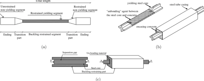
70% of the entire length of the core is restrained by the casing (Sahoo and Chao, 2010). In this bracing system, compression stresses are basically suffered by the restrained part of the core. On the other hand, the yield strength of the steel core is much lower than the steel tube casing, such that the core yields with almost similar behaviour in tension and compression, prior to the casing. Due to this behaviour, the energy dissipation potential of BRBs is significantly increased compared to the ordi-nary bracing systems.
Restrained yielding segment
Rrestrained non-yielding segment Unrestrained
non-yielding segment
Ending Transition Buckling restrained segment Ending
part
Transition part
Total length
R
yielding steel core
"unbonding" agent between the steel core and concrete
encasing concrete
steel tube casing
(a) (b)
P P
Seperation gap
Buckling restraining mechanism Steel core
P P
Un-bonding material
Separation gap
Buckling restraining part (c)
Figure 1: Detail of BRBs in terms of its (a) constituent components, (b) buckling restraining components and
(c) separation gap at steel core-restrainer interface.
Because of the Poisson's effect of the steel core, it expands when it is compressed. Thus, to prevent the axial stress transition from the core to the restrainer, a certain amount of clearance must be provided between the core and concrete to avoid the friction between them. In addition to this gap, in order to ensure that the friction between the core and concrete is nearly zero, a de-bonding agent is applied to the surface of the core (Figure 1(b-c)).
Latin American Journal of Solids and Structures 12 (2015) 2118-2142 2 PROBLEM DESCRIPTION
2.1 Fire scenarios and details of frames studied
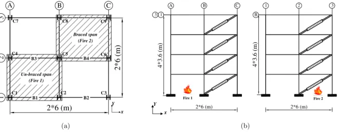
In this work, the influence of BRBs on the fire resistance of a four storey steel structure is compared with that of OCBs. As shown in Figure 2, the frame has 4 storeys with 3.6 meter height at each level. There are 2 bays with 6.0 meter span in the X-direction. The spacing of consecutive frames is 6.0 m in the Y-direction. The structure is assumed to be a typical office building with 3.5 kN/m2 and 5.0 kN/m2 for dead and live design loadings, respectively. Thus, a total line load of 40 kN/m at fire condition is assumed to be uniformly distributed along the length of girders, modelling one-way be-haviour for slabs. For a structural braced frame, the bracing system should be designed to withstand probable horizontal forces, such as wind and earthquake. The structural frame is designed seismically in accordance with the AISC Seismic Provisions for Structural Steel Buildings (AISC, 2002), allowing for the response modification factors of 7 and 6 for BRBs and OCBs, respectively.
Besides, to have a conforming comparison with the fire response of structural members in a build-ing that was tested through Cardbuild-ington test (Lennon, 1997), this study adopts the same section sizes and design criteria used in the referred test.
2*6 (m)
2
*
6
(
m
)
1
2
3
A B C
C1 C2 C3
C4 C5 C6
C7 C8 C9
B3
x
Y Un-braced span
(Fire 1)
B1 B2
Braced span (Fire 2)
B4
2*6 (m)
4
*
3
.6
(
m
)
A B C
2*6 (m)
4
*
3
.6
(
m
)
1 2 3
1
3 B
Fire 1 Fire 2
x
Y
(a) (b)
Figure 2: Dimensions of structural frame in (a) plan and (b) X , Y elevations.
According to the AISC Seismic Provisions (AISC, 2002), the strength of bracing connections must be the smallest value of braces nominal tensile strength and the maximum load they can sustain. Hence, in this study the bracing connections are considered to remain in the elastic domain at all time, and the yielding is allowed for the braces only. In relation to this concept, pinned connections are assumed between two endings of bracing elements and beam-columns. It is noted that the failure and fracture of connections are neglected in the analyses.
Latin American Journal of Solids and Structures 12 (2015) 2118-2142
Storey Column section (edge)
Column section (internal)
Beam section
Ground floor UC 305×305×158 UC 305×305×240 UB 356×171×51
First floor UC 305×305×137 UC 305×305×198 UB 356×171×51
Second floor UC 305×305×137 UC 305×305×198 UB 356×171×51
Third floor UC 305×305×137 UC 305×305×198 UB 356×171×51
Table 1: Cross sections of beams and columns.
As shown in Figure 2(b), a diagonal arrangement of bracing has been considered for both systems. In OCBs, the braces are chosen as rectangular hollow sections (RHS) as shown in Figure 3(a). To have a conforming comparison between the response of BRBs and OCBs, similar bracing sections are used for both resisting systems. RHS are used as the steel tube casing in BRBs, while the cores of rectan-gular sections are inserted within the hollow sections (Figure 3(b)). Concrete used to fill the steel tube (restrainer) is of normal weight type with a density of 2400 kg/m3. The compression strength and Poisson's ratio of concrete are 35 N/mm2 and 0.2, respectively.
a
a
rectangular hollow section (RHS)
Section a-a RHS
restraining system as
RHS in-filled concrete
steel core
a
a
steel core
stiffeners
Section a-a core restrainer
(a) (b)
Figure 3: Overall scheme and cross-section of braces for (a) OCB and (b) BRB systems.
Latin American Journal of Solids and Structures 12 (2015) 2118-2142
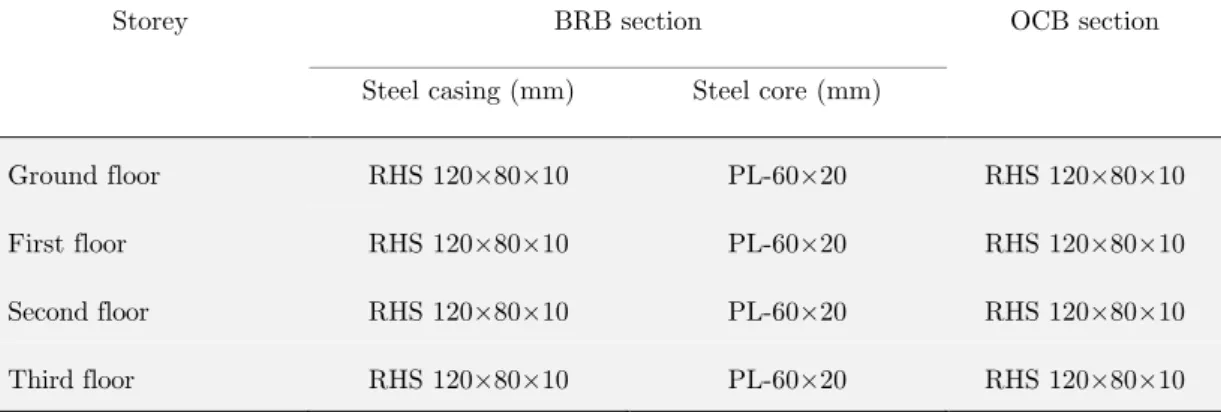
Storey BRB section OCB section
Steel casing (mm) Steel core (mm)
Ground floor RHS 120×80×10 PL-60×20 RHS 120×80×10
First floor RHS 120×80×10 PL-60×20 RHS 120×80×10
Second floor RHS 120×80×10 PL-60×20 RHS 120×80×10
Third floor RHS 120×80×10 PL-60×20 RHS 120×80×10
Table 2: Cross sections of bracing elements used for both bracing systems.
2.2 Material Properties
For the material, temperature-dependent mechanical properties for the steel recommended by Euro-code 3 (EC3) Part 1.2 (EC3, 2005), are adopted (Figure 4(a)). The coefficient of thermal expansion for steel material as proposed by EC3 is used. The effect of creep in the steel at high temperatures is considered implicitly in the stress-strain relations as proposed in EC3. Thermal properties of concrete at elevated temperature are extracted from Eurocode 4 (EC4) Part 1.2 (EC4, 2005), as shown in Figure 4(b).
(a) (b)
Figure 4: Stress-strain relationship of (a) steel and (b) concrete, at elevated temperature.
The moisture content of concrete is considered, using the maximum value of specific heat, which specifies the latent heat of water vaporization. According to EC4 (2005), a maximum value of
2020 J/kg K⋅ for a moisture content of 3% of concrete weight for the siliceous aggregates in concrete
is adopted. For concrete, the value of coefficient of thermal expansion proposed by Lu (2011) is employed.
0 50 100 150 200 250 300 350 400
0 0.05 0.1 0.15 0.2 0.25
S
tr
es
s
(M
p
a
)
Strain
T20°C T200°C T300°C T400°C T500°C T600°C T700°C T800°C T900°C T1000°C
0 0
5 10 15 20 25 30 35
0 0.01 0.02 0.03 0.04 0.05
S
tr
e
ss
(
M
p
a
)
Strain
Latin American Journal of Solids and Structures 12 (2015) 2118-2142 3 NUMERICAL FE MODEL
3.1 Setting of the analysis
A sequentially-coupled thermal (transient)-stress (implicit dynamic) analysis procedure in the Abaqus FE program is utilized for the modelling. This technique is utilized since the stress-displacement solutions that are affiliated to the temperature history have no inverse dependency (Abaqus, 2008). This approach consists of two sequential analysis stages, where the results of the first step are adopted for the analysis in the second step. These steps are as follows:
(1) Heat transfer (transient): carried out to simulate the heat transfer from the outer surface of the heated elements through their cross section and along their length.
(2) Stress analysis (implicit dynamic): carried out to simulate the structural responses of heated elements, which are exposed to fire or thermal loading, resulted from step 1. In order to examine the behaviour of structure after the occurrence of the first local failure, an implicit integration method, which is unconditionally stable, is employed in the Abaqus full dynamic model. To transfer thermal analysis results to that of structural properly, the types of elements are iden-tically assigned in both steps. Furthermore, the time in both steps should be consistent with each other such that the temperature in thermal and structural analyses can be simulated and transferred smoothly. In order to prepare the condition that data can be transmitted more effectively between the analyses, the finite element meshes and their numbering should be the same in both steps. Besides, a mesh convergence study has been conducted in order to investigate mesh sensitivity and it is found that the mesh density of the current model is computationally efficient without a significant loss in accuracy.
3.2 Thermal analysis
The thermal reaction of elements against heating is basically a transient heat transfer process, in which the heat of fire is transmitted to the outer surface of the heated elements by convection and radiation, which is then followed by the conduction into the internal surfaces of the corresponding members. In this study, the fire compartment is simulated as an ISO 834 standard fire curve (ISO 834, 1980) for a period of 90 minutes heating time. For the standard fire exposure, the values of heat convective coefficient, hv =25 (W/m2K), emissivity of fire, εf =0.8, and emissivity of the steel sur-face, εm =0.7, proposed by EC4 (2005) for the composite elements, are used in this paper. Figure 5 shows the heat transfer analysis of the modelled structure with BRBs, exposed to Fire 1 and Fire 2 scenarios for 90 minutes predefined heating time. In the thermal analysis, the model is meshed using the three-dimensional eight-node solid elements (DC3D8) for steel beam, column and bracing ele-ments, as well as the three-dimensional four-node heat transfer quadrilateral shell elements (DS4) for the slabs (Figure 5). In order to improve the accuracy of results, the mesh refinement is implemented along the beams, columns and slabs in the regions of heating. Figures 5(a) and (b) show the reduced mesh sizes at the regions of interest against Fire 1 and Fire 2 loadings, respectively.
Latin American Journal of Solids and Structures 12 (2015) 2118-2142
X Y Z
X
Y Z
(a) (b)
Figure 5: Heat transfer analyses of the selected steel structure with BRBs, for (a) Fire 1 and (b) Fire 2 scenarios.
other stiffer members, the progressive collapse could be prevented. Eventually, the retardation of a global failure of the whole structure can be ensured. Previous studies (Talebi et al., 2014a) have shown that BRBs can effectively prevent the progressive collapse of a structural frame against fire. This is done due to the additional strength this system append to the building, owing to the un-buckled characteristic of bracing components both in tension and compression. Given the advantage of isolated BRB element's well response under fire condition (Talebi et al., 2014b; 2015) and consid-ering the main objective of this paper, i.e., the overall response of BRBs on the fire resistance of a whole structure, it is assumed that bracing elements as well as beam-column-brace connections are un-heated (fire-insulated) throughout the analyses. The results of the nonlinear heat transfer analysis consist of temperature-time (T-t) histories for all nodes within the 3D model. They are subsequently applied as thermal loadings to the structural model.
3.3 Structural analysis
A nonlinear structural model is implemented after the full thermal analysis, using the same FE pro-gram (Abaqus, 2008), taking into account the nodal temperature-time curves previously calculated from the thermal analysis. The three-dimensional eight-node solid elements with reduced integration (C3D8R) are used to mesh all beam, column and bracing elements and three-dimensional four-node shell elements with reduced integration (S4R) are used to mesh slabs.
Latin American Journal of Solids and Structures 12 (2015) 2118-2142
to resist the entire bending moment, axial and vertical loads, such that it enables the beam to expe-rience the catenary effects during heating stage (without the occurrence of failure in the joints). For simulating the beam-slab connections, reinforcing bars and profile decking are modelled in each shell element by defining REBAR element from the Abaqus library. The beam and shell elements are then tied together to simulate the composite action between the steel beam and the composite slab.
3.3.1 Definition of material properties
In the Abaqus package, a classical metal nonlinear material model is selected for the steel, which follows the Von Mises yield function and associated plastic flow rule. A concrete damaged plasticity model (CDP) is utilized for the fundamental relationship of concrete. It contains a combination of non-associated multi-hardening plasticity and isotropic damage behaviour to model the irreversible damage, which occurs through fracturing (Lu, 2011). Concrete has differing behaviours and damage mechanisms under compression and tension. Therefore, the stress-strain relationships for concrete need to be specified both in tension and compression. There are several options to define the tensile stress-strain relationship in the concrete damaged plasticity model. Tensile characteristic of concrete at elevated temperature is specified as the traditional tensile stress-strain relationship. For modelling damaged plasticity in concrete, the relevant values proposed by Jankowiak (2005) are adopted.
4 VERIFICATION OF PROPOSED NUMERICAL MODEL
4.1 Description
The accuracy of the proposed numerical model is validated by a series of tests carried out at Card-ington (Lennon, 1997). To do so, the computed FE temperatures as well as bending moments and stresses within a number of selected elements (refer to Table 3) are contrasted with the comparable values measured during the test.
To have a conforming comparison with the corresponding test, in this part of the study fire is modelled as a natural fire, as observed in the Cardington test. In this paper, the seventh (structural integrity) fire test, whose detail is shown in Figure 6, is chosen for validating the proposed FE results.
4.2 Results
For brevity, a total of four elements, namely, two beams (D1-D2 and E1-E2) and two columns (D1 and D2) as shown in Figure 6 are selected for verifying the numerical accuracy with the test results. For comparisons, several particular points within the cross section of each member are chosen, ac-cording to Table 3.
Figures 7 (a)-(c) compare the temperature distributions across the cross-sections of the specified beams and columns resulted from FE analyses and the test. On close inspection, all curves from numerical models reproduce very close similarity to those from measurements, although the results from the former are slightly higher.
Latin American Journal of Solids and Structures 12 (2015) 2118-2142
stresses generated in the selected columns (Table 3), during the fire. Results show that the FE axial stresses at different locations of external and internal columns are almost similar to the corresponding values recorded during the test.
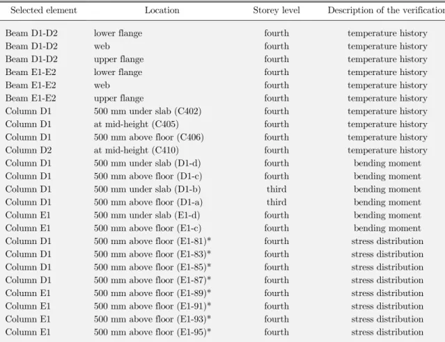
Selected element Location Storey level Description of the verification
Beam D1-D2 lower flange fourth temperature history
Beam D1-D2 web fourth temperature history
Beam D1-D2 upper flange fourth temperature history
Beam E1-E2 lower flange fourth temperature history
Beam E1-E2 web fourth temperature history
Beam E1-E2 upper flange fourth temperature history
Column D1 500 mm under slab (C402) fourth temperature history Column D1 at mid-height (C405) fourth temperature history Column D1 500 mm above floor (C406) fourth temperature history Column D2 at mid-height (C410) fourth temperature history Column D1 500 mm under slab (D1-d) fourth bending moment Column D1 500 mm above floor (D1-c) fourth bending moment Column D1 500 mm under slab (D1-b) third bending moment Column D1 500 mm above floor (D1-a) third bending moment Column E1 500 mm under slab (E1-d) fourth bending moment Column E1 500 mm above floor (E1-c) fourth bending moment Column D1 500 mm above floor (E1-81)* fourth stress distribution Column D1 500 mm above floor (E1-83)* fourth stress distribution Column D1 500 mm above floor (E1-85)* fourth stress distribution Column D1 500 mm above floor (E1-87)* fourth stress distribution Column E1 500 mm above floor (E1-89)* fourth stress distribution Column E1 500 mm above floor (E1-91)* fourth stress distribution Column E1 500 mm above floor (E1-93)* fourth stress distribution Column E1 500 mm above floor (E1-95)* fourth stress distribution
∗ Locations are shown in Figure 6.
Table 3: Specification of the selected elements used for validation of the numerical results.
D
E
1
2
9000
6
0
0
0
UB 356×171×51 UB 305×165×40
U
B
3
5
6
×
1
7
1
×
5
1
U
B
3
5
6
×
1
7
1
×
5
1
9000 mm
6
0
0
0
m
m
Fire exposure border
87 85
83 81
20
y z
D1
E1
20
20 20
95 93
91 89
20
y z
20
20 20
Latin American Journal of Solids and Structures 12 (2015) 2118-2142
(a) (b)
(c)
Figure 7:Comparison of computed T-t curves for the selected points within (a) external (D1) and internal (D2)
col-umns, (b) the cross section of beam D1-D2, and (c) the cross section of beam E1-E2, with test observations.
-150 -100 -50 0 50 100 150
0 50 100 150 200 250
S tr e ss ( M P a ) Time (min)
Point 81- Computed Point 81- Measured Point 83- Computed Point 83- Measured Point 85- Computed Point 85- Measured Point 87- Computed Point 87- Measured
83 .
81
85 87
20 20
z
-250 -200 -150 -100 -50 0 50 100 150 200 250
0 50 100 150 200 250
S tr e ss ( M P a ) Time (min)
Point 89- Computed Point 89- Measured Point 91- Computed Point 91- Measured Point 93- Computed Point 93- Measured Point 95- Computed Point 95- Measured
91 89
93 95
(a) (b)
Figure 8:Comparison of computed axial stress developed in column (a) D1 and (b) E1 with test observations.
Labels for points are as illustrated in Figure 6.
0 50 100 150 200 250 300 350 400 450 500
0 20 40 60 80 100 120 140 160 180
T em p er a tu re ( °°°° C ) Time (min) C 402-Computed C 402-Measured C 405-Computed C 405-Measured C 406-Computed C 406-Measured C 410-Computed C 410-Measured 0 100 200 300 400 500 600 700 800 900 1000
0 20 40 60 80 100 120 140 160 180
T em p er a tu re ( °°°° C ) Time (min) Lower flange-Computed Lower flange-Measured Web-Computed Web-Measured Upper flange-Computed Upper flange-Measured 0 200 400 600 800 1000 1200 1400
0 20 40 60 80 100 120 140 160 180
Latin American Journal of Solids and Structures 12 (2015) 2118-2142
The development of bending moment via elapsed heating time in the selected points within columns (Table 3) is depicted in Figures 9 (a)-(b). The close agreement trends are obviously repeated. By comparing the thermal and structural results obtained from the numerical analyses with the corresponding values measured in the Cardington seventh test (Figures 7-9), it can be concluded that there is a good agreement between both approaches. Relying on this validation, the influence of additional strength provided by BRBs (compared to OCBs) on the structural steel frame against fire will be investigated next, using the verified numerical model proposed in this study.
(a) (b)
Figure 9:Comparison of modelled bending moment in the selected points within column (a) D1 at the third and
fourth storeys, and (b) E1 at the fourth storey with test observations.
5 RESULTS AND DISCUSION
5.1 Fire resistance provided by BRBs on a structural steel frame
Herein, in order to examine the fire resistance of BRBs on a three dimensional multi-storey structure, the response of this system is studied and compared with that of OCBs, under two fire scenarios defined readily in Figure 2.
5.1.1 Un-braced span fire (Fire 1)
To understand the mechanism of load redistribution in BRBs and OCBs under Fire 1, the develop-ment of axial forces in the entire columns (nominated in Figure 2(a)) is plotted in terms of 90 minutes of predefined heating time in Figures 10-12. Results show that the overall scheme of axial force distribution in all columns under Fire 1 scenario is almost similar for both bracing systems.
Considering the position of columns and bracing arrangements (refer to Figure 2), it is seen that the greatest restraint is imposed to column C5 by the surrounding structural members. Hence, it is expected that the major axial force is experienced by C5 during heating time, that is followed by the failure of this column prior to the other columns. Although the greatest axial force is experienced by C5 with magnitudes of 1462 kN and 1333 kN in BRBs and OCBs, respectively (Figure 11), its buckling does not lead to the global failure of this column. This is because C5 top location is restrained by bracing elements and it is not free to descend downwards. As a result, the first failure is switched
-400 -300 -200 -100 0 100 200 300 400 500 600 700
0 20 40 60 80 100 120 140 160 180
B en d in g m o m en t (k N .m ) Time (min) D1-a- Computed D1-a- Measured D1-b- Computed D1-b- Measured D1-c- Computed D1-c- Measured D1-d- Computed D1-d- Measured -300 -200 -100 0 100 200 300 400 500
0 20 40 60 80 100 120 140 160 180
Latin American Journal of Solids and Structures 12 (2015) 2118-2142
Figure 10:Comparison of axial force developed in the columns of 1-axis, for both bracing systems under Fire 1.
Figure 11:Comparison of axial force developed in the columns of 2-axis, for both bracing systems under Fire 1.
Figure 12:Comparison of axial force developed in the columns of 3-axis, for both bracing systems under Fire 1.
to column C4, which is highly restrained (after C5) and is directly exposed to Fire 1. C4 buckles with axial forces of 1119 kN and 1010 kN after 49 minutes and 24 minutes of heating time in BRBs and OCBs, respectively (Figure 11). By the buckling of C4, the loads previously carried by this column drop to negligibly small values of 192 kN and 50 kN in BRBs and OCBs, respectively. This means
0 100 200 300 400 500 600 700 800 900 1000
-10 0 10 20 30 40 50 60 70 80 90 100
A x ia l F o rc e (k N ) Time (min) C1- BRBs C1- OCBs C2- BRBs C2- OCBs C3- BRBs C3- OCBs 0 200 400 600 800 1000 1200 1400 1600
-10 0 10 20 30 40 50 60 70 80 90 100
A x ia l F o rce (k N ) Time (min) C4- BRBs C4- OCBs C5- BRBs C5- OCBs C6- BRBs C6- OCBs 0 100 200 300 400 500 600 700 800 900
-10 0 10 20 30 40 50 60 70 80 90 100
Latin American Journal of Solids and Structures 12 (2015) 2118-2142
that the majority of C4 load is transferred to the other stiffer members at the moment that its buckling occurs in both bracing systems.
When fire happens in the un-braced span, the temperature of structural elements, which are di-rectly exposed to fire, increases and this is followed by the expansion of four heated columns (C1, C2, C4 and C5) in the supported bay. Since the expansions of these columns are restricted by the adjacent elements, a big axial force is generated within them.
Subsequently, in order to balance overall induced axial force within the heated frame, the axial load is reduced in the unheated columns, all of which experience only a room temperature. Conse-quently, these cooler columns undergo a declination in their axial load distribution at the time that the hotter columns face a rise in their axial load trend (Figures 10-12). This fact can be observed from Figures 10-12, which show that the axial forces in C3, C6, C7, C8 and C9 fall to 509 kN, 550 kN, 510 kN, 560 kN and 415 kN, respectively for BRB system. The corresponding forces are 416 kN, 502 kN, 457 kN, 510 kN and 380 kN, respectively in OCB system. It can be seen that the entire cool columns have experienced a larger amount of axial forces in BRBs as compared to OCBs, owing to a higher restraint the former provides to the structural frame in comparison to the latter.
Diagrams show that there is a sudden change in the magnitudes of axial forces for all columns after 49 minutes and 24 minutes of heating time (C4 buckling time) for BRBs and OCBs, respectively (Figures 10-12). This sudden change can be a good representation of the load redistribution phenom-ena from the heated buckled column (C4) to the neighbouring structural members. Moreover, it can be seen that most of the columns have a gradual change in their axial force, which is accompanied by the abovementioned sudden increase. This gradual change in the axial forces is attributed to the restraint provided to the expansion and contraction of heated columns by neighbouring structural stiffer members. The higher restraint provided to the structural frame by BRBs compared to OCBs explains why the axial forces of all columns expand gradually in a longer tolerable heating time (49 min) for the former, in comparison to the latter with a comparable period of 24 minutes.
The aforesaid process is observed in the entire heating columns, except for the corner column (C1). Results show that although C1 is directly exposed to fire and it expands, its compression forces reduce to 290 kN and 269 kN after heating periods of 49 minutes and 24 minutes in BRBs and OCBs, respectively (Figure 10).
The cause of this event can be described by the free-body diagrams of beams B1 and B2 (nomi-nated in Figure 2(a)) as depicted in Figure 13. In this diagram, the vertical movement due to the expansion of heated column is considered as δ. Assuming the moment in C1, whose location is represented at the end of B1 at the left hand side, is free to move downwards and rotate, it is apparent in Figure 13 (a) that a displacement of δ at C2 location creates a greater displacement at C1 position. Consequently, in order to make the displacement at the position of C1 equal to δ , an extra downward force should be imposed at this point (Figure 13(b)). The corresponding additional force can be provided by appending an extra tension force at the C1 location. This offers the reason why a decli-nation in the axial force of heated column at the corner is observed (Agarwal, 2011).
Latin American Journal of Solids and Structures 12 (2015) 2118-2142
unheated members, by means of bracing members in both resisting systems. As shown in Figure 14, the corresponding demand in BRBs is higher with a longer heating time in comparison to that of OCBs.
δ
Heated corner column
(C1)
Neighboring heated column
(C2)
Ambient temperature column
(C3)
B1 B2
δ
Heated corner column
(C1)
Neighboring heated column
(C2)
Ambient temperature column
(C3)
B1 B2
(a) (b)
Figure 13:Deformed pattern scheme of columns at 1-axis, under heating at un-braced span (corner bay).
Figure 14: Total axial loads developed within nine columns during Fire 1.
From this observation, it can be concluded that BRBs are more capable in redistributing the loads previously carried by the buckled column (C4) to the adjacent stiffer load bearing members, compared to OCBs.
Figures 15 and 16 demonstrate the development of axial force and bending moment at the endings of beam B3 (nominated in Figure 2 (a)), respectively, as its displacement grows under Fire 1 in both bracing systems. As shown in these figures, the variation of axial tension force and bending moment via displacement of B3 is normalized by the ratios of T Ty and M Mp , respectively. Here, Mp and
y
T denote the plastic moment and tensile yield strength of the beam, respectively.
As readily described, when a fire occurs in the un-braced bay, C4 fails prior to the other columns and this is followed by the growth of tensile force in B3, due to the catenary action in the beam. Increases in tensile force in B3 continue up to the ratios of 0.102 and 0.116 with the displacements of about 730 mm and 813 mm in BRBs and OCBs, respectively (Figure 15). The development of tensile force in the corresponding beam results to the pulled-in of the heated columns at the un-braced span (Sun et al., 2012a). Finally, this inward movement of the columns leads to the reduction of tensile force in B3 up to ratios of 0.079 and 0.088 with the displacements of about 1310 mm and 1440 mm in BRBs and OCBs, respectively (Figure 15). By the buckling of C4 and its vertical movement, other columns above it tend to descend downwards. As a direct result, the bending moment in B3 increase
0 100 200 300 400 500 600 700 800 900
-10 0 10 20 30 40 50 60 70 80 90 100
A
x
ia
l F
o
rc
e
(k
N
)
Time (min)
Latin American Journal of Solids and Structures 12 (2015) 2118-2142
dramatically (Figure 16). Apparently, the bending moment in this beam grows up to the ratios of 1.20 and 1.33 with the displacements of about 104 mm and 116 mm for BRBs and OCB, respectively. From this stage, the change of bending moment in the corresponding beam is almost constant, for both bracing system as illustrated in Figure 16.
Figure 15: Comparison of axial tension force ratio developed in beam B3
endings for both bracing systems, under Fire 1.
Figure 16: Comparison of bending moment ratio developed in beam B3
endings for both bracing systems, under Fire 1.
As shown in Figures 15-16, it is obvious that tensile force and bending moment as well as the dis-placement of beam B3 in OCBs under Fire 1 are about 10% more than the corresponding values in BRB system. This may be because of the higher restraint provided to the whole structure by BRBs. As a result, the movements of columns in this system are restricted more than OCBs. Consequently, the bending moment and tensile forces at the endings of beam B3, which are generated by the vertical movement of column C4 (at the top location) in BRB system are lesser than the comparable values in OCBs.
From the results, it can be seen that BRB elements could play a significant role in maintaining the stability of a structural frame after the occurrence of the first local failure in column C4. In order to track this concept more exhaustively, the axial displacement of top point location of buckled
-0.15 -0.1 -0.05 0 0.05 0.1 0.15
-400 -200 0 200 400 600 800 1000 1200 1400 1600
T
/Ty
Displacement (mm)
BRB system
OCB system
-1.5 -1 -0.5 0 0.5 1 1.5
-400 -200 0 200 400 600 800 1000 1200 1400 1600
M
/M
p
Displacement (mm)
BRB system
Latin American Journal of Solids and Structures 12 (2015) 2118-2142
column (C4) is plotted against predefined heating time of 90 minutes in Figure 17. It is observed that in the primary heating stage, there is an initial displacement in C4, which is the result of initial expansion of this column due to temperature rise. Apparently, this vertical movement (1.67 mm) is almost equal for both bracing systems (Figure 17). After this stage, the surplus strength provided to the building through bracing elements helps the structural frame to keep its stability. Subsequently, there is an upward movement in the corresponding point up to the maximum values of 6 mm and 8.7 mm after 30 minutes and 22 minutes in BRBs and OCBs, respectively. After this stage, there is a sudden fall in the axial movement of C4 at 49 minutes and 24 minutes in BRBs and OCBs, respec-tively. At this moment, a transient instability is occurred in the structural frame, which is reflected as a sudden failure of this column at mentioned times, for both bracing systems. However, the struc-tural frame gains its overall stability after a short period of time. This is because the force previously carried by the buckled column is transferred to the stiffer members (by means of bracing elements) after the occurrence of the first local instability. Finally, maximum displacements of 14.62 and 18 mm are found at the end of 90 minutes heating time in BRBs and OCBs, respectively (Figure 17).
-20 -15 -10 -5 0 5 10 15
0 10 20 30 40 50 60 70 80 90 100
A
x
ia
l D
is
p
la
ce
m
en
t (
m
m
)
Time (min)
BRBs OCBs
Instability
Transient Instability
Figure 17: Comparisonof vertical displacement at top point location of C4 for both bracing systems, under Fire 1.
From the results depicted in Figure 17, it is observed that BRBs prevent the axial movement of C4 more effectively than OCBs, owing to the higher restraint the former provides to the structural frame, as compared to the latter. Moreover, it is seen that the transient instability of frame with BRBs is occurred after a period of 25 minutes later in contrast to OCBs. From this observation, it can be concluded that BRBs are more capable in maintaining the stability of structure against fire at un-braced span, compared to OCB system.
5.1.2 Braced span fire (Fire 2)
Latin American Journal of Solids and Structures 12 (2015) 2118-2142
Figure 18:Comparisonof axial force developed in the columns of 1-axis, for both bracing systems under Fire 2.
Figure 19: Comparison of axial force developed in the columns of 2-axis, for both bracing systems under Fire 2.
Figure 20: Comparison of axial force developed in the columns of 3-axis, for both bracing systems under Fire 2.
0 100 200 300 400 500 600 700 800 900 1000
-10 0 10 20 30 40 50 60 70 80 90 100
A
x
ia
l F
o
rc
e
(k
N
)
Time (min)
C1- BRBs C1- OCBs C2- BRBs C2- OCBs C3- BRBs C3- OCBs
0 200 400 600 800 1000 1200 1400 1600 1800
-10 0 10 20 30 40 50 60 70 80 90 100
A
x
ia
l F
o
rc
e
(kN
)
Time (min)
C4- BRBs C4- OCBs C5- BRBs C5- OCBs C6- BRBs C6- OCBs
0 200 400 600 800 1000 1200
-10 0 10 20 30 40 50 60 70 80 90 100
A
x
ia
l F
o
rc
e
(k
N
)
Time (min)
Latin American Journal of Solids and Structures 12 (2015) 2118-2142
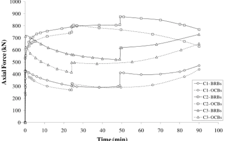
By rising the temperature of heated columns due to Fire 2 loading, the axial force grows rapidly within the corresponding columns, since their expansion is restricted by the neighbouring structural elements. Accordingly, the greatest axial force is experienced by C5 with the peak values of 1530 kN and 1442 kN after 60 minutes and 31 minutes in BRBs and OCBs, respectively (Figure 19). As mentioned previously, despite of the highest axial force generated within C5, the first failure is switched to the other heated column, which is free to descend downwards. In the case of Fire 2, column C6 is highly restrained (after C5) so that the first failure is occurred in this column with axial loads of 1235 kN and 1110 kN after elapsing time of 60 minutes and 31 minutes in BRBs and OCBs, respectively (Figure 19).
By the buckling of C6, its axial loads are reduced to 212 kN and 59 kN in BRBs and OCBs, respectively (Figure 19), and the load it was shed previously shifts to the stiffer load bearing elements. This is followed by a rapid growth in the axial load of other framing columns, for both bracing systems (Figures 18-20). In balancing the big generated axial force within the heated columns, other unheated columns (C1, C2, C3, C4 and C7), which remain approximately at the room temperature, experience a decrease in axial load. Consequently, the axial loads in C1, C2, C3, C4 and C7 reduce to 425 kN, 616 kN, 728 kN, 600 kN and 532 kN, respectively for BRBs. The corresponding values are 379 kN, 561 kN, 457 kN, 550 kN and 477 kN, respectively in OCBs, as shown in Figures 18-20.
Latin American Journal of Solids and Structures 12 (2015) 2118-2142
structural frame achieves its overall stability by transferring the load from buckled column to the adjacent members. In the end, maximum displacements of 13 mm and 16.2 mm are experienced by C6, after elapsing period of 90 minutes under Fire 2 in BRBs and OCBs, respectively. It can be observed that BRBs can effectively prevent the vertical movement of buckled column, owing to a higher restraint they provide to the frame as compared to OCBs.
-20 -15 -10 -5 0 5 10
0 10 20 30 40 50 60 70 80 90 100
A
x
ia
l D
is
p
la
ce
m
en
t (
m
m
)
Time (min)
BRBs OCBs
Instability
Transient Instability
Figure 21:Comparisonof vertical displacement at the top point location of C6 for both bracing systems under Fire 2.
A comparison between the results shows that the vertical displacement of C6 under heating at braced span is lesser than that in C4 against heating at un-braced span. This can be attributed to the direct contact of bracing elements to Fire 2, which effectively plays an important role in redistributing the loads from buckled columns to the stiffer elements. The total axial force tolerated by the entire framing columns against heating under Fire 2 is depicted in Figure 22. Obviously, the corresponding value for BRBs is higher than the comparable value for OCBs because of a higher restraint the former provides to the frame.
Figure 22:Total axial loads developed within nine columns during Fire 2.
By comparing the plotted graphs in Figure 22 with those shown in Figure 14, it can be seen that the small increase in the total load of columns, which is gained after a sharp drop in the curves due to
0 100 200 300 400 500 600 700 800 900
-10 0 10 20 30 40 50 60 70 80 90 100
A
x
ia
l F
o
rc
e
(k
N
)
Time (min)
BRBs
Latin American Journal of Solids and Structures 12 (2015) 2118-2142
Fire 2 is higher than that from Fire 1. This is attributed to the higher amount of total load transferred from buckled column to the unheated members in heating at the braced span as compared to the un-braced span. This means that the bracing elements are more efficient in redistributing the loads from the heated column to the adjacent members for Fire 2 scenario in comparison to Fire 1, in both bracing systems. From this observation, it can be concluded that heating at braced span exposes the whole building to a lesser risk and damage, compared to the occurrence of fire at the un-braced span in both bracing system. Besides, it is observed that BRBs are more capable in redistributing the loads from the heated buckled columns to the other unheated members, attributed to a better performance of this system in re-stabilization of structural frame, as compared to the ordinary systems.
After the buckling of C6, it descends downwards with the growth in bending moment and tensile force in beam B4 (nominated in Figure 2(a)) due to the existence of catenary action in the beam (Sun et al., 2012a). As shown in Figures 23, T Ty in B4 increase up to the peak ratios of 0.08 and 0.092
with displacements of 713 mm and 794 mm in BRBs and OCBs, respectively, owing to the pull-in of heated connected columns. Finally, this inward movement in the corresponding columns causes the reduction of tensile force in beam B4 to ratios of 0.067 and 0.07 with displacements of 1182 mm and 1317 mm for BRBs and OCBs, respectively (Figure 23).
Figure 23:Comparison of axial tension force ratio developed in beam B4
endings for both bracing systems, under Fire 2.
When C6 buckles, it descends downwards and other columns above it tend to move down as well. As a direct effect, the bending moment in B4 increases considerably. As shown in Figure 24, the growth of bending moment in this beam continues up to ratios of 0.96 and 1.07 with displacements of 93 mm and 105 mm for BRBs and OCB, respectively. From this stage, the change in bending moment is almost constant, for both bracing systems until the ultimate displacements of 1181 mm and 1316 mm are formed by the former and the latter, respectively.
When comparing the tensile force and bending moment ratios developed within B4 (Figures 23-24), it can be seen that the corresponding values for BRBs are lesser than those for OCBs. This is again attributed to the higher restraint provided to the frame by the former. On the other hand, from Figures 23-24 it is evident that the tensile force and the bending moment as well as the displacement of B4 under Fire 2 scenario, are lesser than the comparable values for B3 against heating under Fire
-0.15 -0.1 -0.05 0 0.05 0.1 0.15
-400 -200 0 200 400 600 800 1000 1200 1400
T
/T
y
Displacement (mm)
Latin American Journal of Solids and Structures 12 (2015) 2118-2142
1. This is directly related to the position of bracing members at the braced span and their influence on the load transferring from buckled column to the unheated elements, shown by a reduction of vertical movement in the buckled column. Consequently, the bending moment and the tensile force at beam endings, which are created by a vertical movement of the buckled column in Fire 2, are lesser than the comparable values in Fire 1.
Figure 24:Comparisonof bending moment ration developed in beam B4
endings for both bracing systems, under Fire 2.
6 CONCLUSIONS
In this paper, the efficiency of using BRBs in enhancing the fire resistance of a framing building in comparison to the use of OCB system is investigated, using the "sequentially coupled thermal-stress" analysis. For this purpose, a three-dimensional structural model with a diagonal arrangement of brac-ing members was simulated in Abaqus program. In order to investigate the effect of fire location, two different fire scenarios were considered as "braced" and "un-braced" heating spans. Several significant conclusions can be drawn as follows.
1. At fire, by the rise in the temperature of columns, which are directly exposed to fire, an expansion is occurred in the corresponding columns. Since these elements are restrained by the adjacent members, a large axial force is generated within them. Consequently, they experience a rise in their axial load distribution.
2. As the temperatures of heated columns increase, the temperatures in the unheated columns remain almost unchanged. In order to balance the thermally induced large force within the former, the latter experience descend in their axial load trend.
3. Despite of the expansion and temperature increase in a heated column, which is located at the corner, it experiences a drop in its axial (compression) load distribution, owing to the growth of tensile force within this column.
4. The failure time of buckled column in the braced span fire is much higher than that of the case when heating is applied on un-braced span. Hence, Fire 2 condition induces lesser risk and overall damage in the entire building in comparison to Fire 1 scenario, for both bracing systems.
-1.5 -1 -0.5 0 0.5 1 1.5
-400 -200 0 200 400 600 800 1000 1200 1400
M
/M
p
Displacement (mm)
Latin American Journal of Solids and Structures 12 (2015) 2118-2142
5. The vertical movement of heated (buckled) column in the structural frame with BRBs is lesser than that with OCBs. Consequently, the tensile force and bending moment of the beam adjacent to the buckled column in the former is lesser than the latter.
6. BRB elements provide higher stiffness in the structural frame and as a direct result they impose greater thermally induced axial forces within the columns as compared to OCB system, for both fire scenarios.
7. BRBs is more efficient in redistributing the load that was shed by a heated column to the unheated members as well as increasing the failure time of a buckled column, resulting in a better fire resistance of the whole building in comparison to OCBs.
8. BRBs manifest an improved performance in re-stabilization of structural frame against various fire loadings, following by a superior fire resistance response of a whole building, as compared to the ordinary system.
Acknowledgements
The research is based upon the work supported by the School of Graduate Studies (SPS), Universiti Teknologi Malaysia (UTM).
References
Abaqus version 6.9., (2008). Abaqus analysis user's manual. Providence: SIMULIA.
Agarwal, A., (2011). Stability behavior of steel building structures in fire conditions. PhD thesis, Purdue University. Agarwal, A., Varma, A.H., (2014). Fire induced progressive collapse of steel building structures: The role of interior gravity columns. Engineering Structures 58: 129-140.
AISC., (2002). Seismic provisions for structural steel buildings-including supplement No.1, ANSI/AISC 341-05. Amer-ican Institute of Steel Construction, Chicago.
Bailey, C.G., Lennon, T., Moore, D.B., (1999). The behaviour of full-scale steel-framed buildings subjected to com-partment fires. J. Structural Engineering 77(8): 15-21.
British Standards Institution BS 476, (1987). Fire tests on building materials and structures, part 20: methods for determination of the fire resistance of elements of Construction (General Principles). British Standards Institution, London, UK.
Couto, C., Vila-Real, P., Lopes, N., Rodrigues, J.P., (2013). Buckling analysis of braced and unbraced steel frames exposed to fire. Engineering Structures 49: 541-559.
EC3., (2005). Eurocode 3: Design of steel structures-part 1-2: general rules-structural fire design. British Standards Institution, BS EN 1993-1-2, London, UK.
EC4., (2005). Eurocode 4: Design of composite steel and concrete structures- part 1-2: general rules-structural fire design. British Standards Institution, BS EN 1994-1-2, London, UK.
ISO (International Standards Organization) 834, (1980). Fire resistance tests, elements of building construction, Swit-zerland: International Standards Organization.
Jankowiak, T., (2005). Identification of parameters of concrete damage plasticity constitutive model. Publishing house of Poznan University of Technology, Poznan, ISSN 1642-9303.
Latin American Journal of Solids and Structures 12 (2015) 2118-2142
Li, B., Dong, Y.L., Zhang, D.S., (2015). Fire behaviour of continuous reinforced concrete slabs in a full-scale multi-storey steel-framed building. Fire Safety J. 71: 226–237.
Lu, H., (2011). FE modelling and fire resistance design of concrete filled double skin tubular columns. J. Constructional Steel Research 67: 1733-1748.
Robinson, J.T., Latham, D.J., (1986). Fire resistant steel design - the future challenge. Design of structures against fire, in Anchor R.D., Malhotra H.J., Purkiss J.A. (eds): 225-236.
Sahoo, D.R., Chao, S.H., (2010). Performance-based plastic design method for buckling restrained braced frames. Engineering Structures 32: 2950-2958.
Sun, R.R., Huang, Z., Burgess, I.W., (2012a). The collapse behaviour of braced steel frames exposed to fire. J. Con-structional Steel Research 72: 130-142.
Sun, R.R., Huang, Z., Burgess, I.W., (2012b). Progressive collapse analysis of steel structures under fire conditions. Engineering Structures 34: 400-413.
Talebi, E., Tahir, M., Zahmatkesh, F., Kueh, A., (2014a). Comparative study on the behaviour of buckling restrained braced frames at fire. J. Constructional Steel Research 102: 1-12.
Talebi, E., Tahir, M., Zahmatkesh, F., Yasreen, A., Mirza, J., (2014b). Thermal behaviour of cylindrical buckling restrained braces at elevated temperatures. The Scientific World J. 2014: 1-13.
Talebi, E., Tahir, M., Zahmatkesh, F., Kueh, A., (2015). A Numerical analysis on the performance of buckling re-strained braces at fire-Study of the gap filler effect. Steel and Composite Structures, an International Journal (In Press).
The Building Regulations, (2000). Fire Safety, Approved Document B. HMSO 2000.
Wald, F., Simoes da Silva, L., Moore, D.B., Lennon, T., Chladna, M., Santiago, A., Benes, M., Borges, L., (2006). Experimental behaviour of a steel structure under natural fire. Fire Safety J. 41(7): 509-522.