*e-mail: [email protected]
Article presented at the XV CBECIMAT, Natal - RN, November/2002
The Use of a Vickers Indenter in Depth Sensing Indentation
for Measuring Elastic Modulus and Vickers Hardness
Adonias Ribeiro Franco Jr.a, Giuseppe Pintaúdeb, Amilton Sinatoraa, Carlos Eduardo Pinedoc, André Paulo Tschiptschina* a
Dpto. de Eng. Metalúrgica e de Materiais and Dpto. de Eng. Mecânica, Escola Politécnica, USP, Av. Prof. Mello Moraes, 2463, 05508-900 São Paulo - SP, Brazil
b
Dpto. Acadêmico de Mecânica, Centro Federal de Educação Tecnológica do Paraná Av. Sete de Setembro, 3165, 80230-901 Curitiba - PR, Brazil
c
Núcleo de Pesquisas Tecnológicas, Universidade de Mogi das Cruzes Av. Dr. Cândido Xavier de A. Souza 200, 08780-210 Mogi das Cruzes - SP, Brazil
Received: January 27, 2003; Revised: January 26, 2004
Depth sensing indentation is a powerful experimental technique for determining mechanical properties of materials. In this work a computational routine was developed based on Oliver-Pharr method for measuring a more precise values of elastic modulus using a Fischerscope H100 - depth sensing indentation apparatus, with a Vickers indenter. This computational routine aims also to measure Vickers hardness, as the equipment does not have software for this purpose. From indentation data it was possible to determine initial unloading stiffness, contact depth, pro-jected contact area, reduced modulus, elastic modulus and Vickers hardness of materials. The validity of the routine was verified analyzing two coatings and nine bulk specimens with different elastic-plastic behaviors.
It was verified that the elastic moduli determined through the software of the equipment resulted in great discrepancies when low loads were applied. A good estimate of the elastic moduli of the tested materials is given by the developed routine. For several testing loads, the diagonals deter-mined by means of analytical procedure were compared with the same diagonals measured by image analysis. A good estimate of the Vickers hardness of the above-mentioned materials is given by the developed routine using different testing loads.
Keywords:depth sensing indentation, elastic modulus, Vickers hardness, Oliver-Pharr method, ISE effect
1. Introduction
Load and displacement sensing indentation technique allows determining mechanical properties at penetration depths as low as 20 nm, avoiding the substrate effect on the measurements1. The possibility to carry out tests in so small
scales makes this technique one of the tools chosen to char-acterize mechanical properties of thin films, coatings, sec-ond phase particles and magnetic hard disk recording me-dia2-4.
A well defined indenter geometry is required to get well defined indentation impressions. A perfect tip shape is dif-ficult to achieve. Berkovich is a three-sided pyramid, and
provides a sharply pointed tip, compared to the Vickers indenter, which is a four-sided pyramid and has a slight off-set (0.5- µm)5,6. This is the main reason why three-sided
Berkovich indenters are used in depth sensing indentation machines. However, any indenter with a sharp tip suffers from a finite but an exceptionally difficult to measure tip bluntness. Experimental procedures have been developed to correct the tip shape, of both Vickers and Berkovich indenters1, 7-10.
pro-posed in 1992 by Oliver and Pharr7, which has its origins in
an earlier treatment by Doerner and Nix11. Nowadays, both
methods are accepted for the analysis of the indentation data by the ISO/FDIS 14577-1 standard12. The Oliver-Pharr
method consists in a series of loading cycles to avoid ther-mal drift and plastic reversion, while the Doerner-Nix method uses only a single cycle to obtain the indentation data. The Fischerscope H100 - depth sensing indentation machine uses the latter method, which is less time consum-ing and simpler but takes into account only a few data points, leading to greater inaccuracy. Moreover, the Fischerscope H100 uses the constant hardness calibration method8,13 to
correct the indenter tip shape, which is not adequate since work-hardening may happen during the test.
The Oliver-Pharr method is widely used in depth sens-ing indentation machines with Berkovich indenter. How-ever, it is equally applicable to the case depth sensing in-dentation using a Vickers indenter, with good results as men-tioned in literature8,14,15. The depth sensing indentation
machine used in this work analyzes indentation data using a software based on the Doerner-Nix method, and uses an incorrect area function to describe the indenter tip shape, leading to overestimated elastic modulus and hardness val-ues due to ISE effect - indentation size effect16. Addition-ally, the Fischerscope apparatus software does not give Vickers numbers, which are useful to compare with well-known data of phases and micro-constituents given in lit-erature.
The present work aims to develop a computational rou-tine based on the Oliver-Pharr method for measuring more precise values of elastic modulus and to obtain Vickers hard-ness numbers, using a Fischerscope H100 - depth sensing indentation apparatus, equipped with a Vickers diamond indenter.
2. Theoretical Aspects
Depth sensing indentation technique consists of print-ing an impression on the material surface by applyprint-ing a known load with an indenter of known geometry and sub-sequently analyzing the load vs. displacement data. Equa-tions from the elastic punch theory can be used to deter-mine the elastic modulus, E, and hardness, H, provided that the following conditions during the initial withdrawal of the indenter are ensured:
• the material’s recovery follows an elastic behavior; • the contact area between the indenter and the
speci-men remains constant.
In this case, the Sneddon’s solutions17,18 for the case of
the indentation of an elastic half-space for a cylindrical punch approach to the elastic behavior. One of the Sneddon’s solutions leads to a simple relation between the load, P, and the penetration depth, h, of the form:
(1)
where a is the radius of the cylinder; µ is the shear modulus; and ν is Poisson’s ratio. Knowing that the area of the con-tact circle projected onto the surface, Ac, is equal to πa2 and
that the shear modulus is related to the elastic modulus in the following way:
(2)
and substituting (2) in (1) and differentiating the obtained expression with respect to h:
(3)
one can obtain the contact stiffness S = dP/dh. The elastic modulus, E, can be taken directly from the initial unloading slope, S, when Poisson’ ratio, ν, and contact area, Ac, are given. The latter can be measured independently as a func-tion of contact depth, hc.
As the elastic modulus of the indenter is not infinite, Eq. 3 should be written in terms of combined elastic modu-lus specimen/indenter (Er), which is, according to Hertz Equation:
(4)
where E, Ei, ν and νi are the elastic moduli and Poisson’s ratios of the specimen and indenter, respectively.
Therefore, for the indentation of a plane surface of a semi-infinite elastic solid by a rigid punch, Eq. 3 can be rewritten:
or (5)
The above Equation shows that, for axisymmetric indenters, the relationship between unloading stiffness, S, and contact area, Ac, does not depend upon indenter geom-etry. Pharr, Oliver, and Brotzen19 have shown
experimen-tally that the analysis used for determining elastic moduli and contact areas from contact stiffness S is not limited to punch geometry. Using finite elements method, King20 has
introduced to Eq. 5 a correction factor for non-axisymmetric indenters:
where b corresponds to a correction factor related to the lack of symmetry of the indenter, which is equal to 1.0124 for Vickers indenters, and Acis the projected contact area.
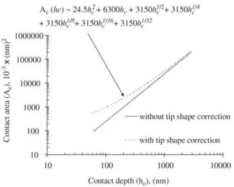
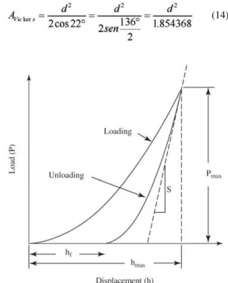
Figures 1 to 3 show the main parameters used in analyzing indentation data.
In Figs 1 and 2, hmax corresponds to the maximum depth,
a to the half-diagonal projected on the surface, hf to the residual depth, hc to the contact depth, and hs to the deflec-tion depth. In Fig. 3, S corresponds to the unloading stiff-ness for h = hmax.
As the unloading from hmax to hf is elastic, one of the Sneddon’s solutions 8, for a conical punch (Figs. 1 and 2),
shows that the deflection of the surface at the contact is:
(7)
Another Sneddon’s solution shows that, for h = hmax, the load is related to the elastic depth:
(8)
Substituting (7) in (8) and noting that the contact area of interest is that at peak load, P = Pmax, it follows:
or (9)
To determine the contact depth from experimental data, one can note that in Fig. 1:
Figure 1. Profile of the surface before and after indentation.
Figure 2. Main parameters used in analyzing unloading vs. indenter depth curves.
(10)
Therefore:
(11)
Considering that usually the indenters are not conical, but square or triangular base pyramids (Vickers or Berkovich indenters) it must take into account that for any revolution paraboloyd (including Vickers indenters), ε is about 0.75 19.
As one can see in Fig. 4a, the contact area, Ac, can be expressed as a function of the diagonal d21:
(12)
Substituting this expression in Eq. 6, one obtains the diagonal as a function of the indentation parameters:
(13)
Eventually, the Vickers hardness numbers can be deter-mined by the average diagonal, d, estimated from such pa-rameters:
(14)
(15)
3. Experimental Details
3.1. Equipment and indentation procedure
A Fischerscope H100 - depth sensing indentation ma-chine equipped with a Vickers diamond indenter,
manufac-tured by Helmut Fischer GmbH, was used. Such equipment
allows applying loads from 1 mN to 1000 mN and register-ing penetration depths as a function of applied loads. Other important testing characteristics of the equipment are:
• control of loading and unloading rates (dP/dt and
d√ P/dt);
• long or short delay times at maximum load; • minimum step among indentations equal to 10 mm; • definition of the number and position of the
indenta-tions (mapping).
Figure 4. a) Vickers indenter: Ac(d) = d2/2; β [≡ (180 - 2α)/2]= 22°; and d = 2a. b) Under loading, the apex for Vickers indenter, 2Ψ, is equal to 148°.
(a)
(b)
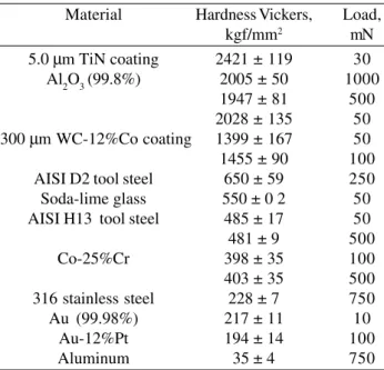
Table 1 shows the main testing conditions.
In all cases the indentation depth did not surpass 10% of the specimen thickness (film or substrate), avoiding any contribution from the substrate22.
3.2. Materials
The materials used in this study were chosen in order to include a wide range of hardness and elastic modulus val-ues: PVD TiN and HVOF WC-12%Co coatings, alumina, AISI D2 and AISI H13 tool steels, AISI 316 stainless steel, aluminum, gold, soda-lime glass, Au-12%Pt and Co-25%Cr odontological alloys. Table 2 presents elastic moduli for these materials reported in the literature.
Bulk specimens were mechanically polished and finished until 1 µm diamond paste. The AISI H13 tool steel speci-mens coated with TiN and with WC - 12%Co were care-fully cleaned using an ultra-sound apparatus in alcohol bath and subsequently dried in warm air. The WC-12%Co coat-ing thickness is about 300 µm, while the TiN coating thick-ness is about 5 µm.
3.3. Analytical procedure used by Fischerscope equip-ment
Fischerscope procedure for measuring hardness and elas-tic modulus consists in estimating the initial slope from unloading data based on the Doerner-Nix analytical treat-ment and subsequently calculating the correct depth through a calibration curve, previously established for tip-shape indenter correction, frequently called hardness constant method8,13.
Figure 5 shows the load-displacement data for alumina. Considering the unloading curve, the initial unloading slope, defined as contact stiffness, dP/dh = S, is determined tak-ing the upper 1/3 of the unloadtak-ing data and fitttak-ing it by a linear relation of the form:
(16)
where .
A straight line is fitted to the unloading curve down to its first 1/3 region and then extrapolated to zero, determin-ing the depth hs and stiffness S.
Fitting the unloading data by a linear relation, yields
S = 0.4719 mN/nm and hs= 84 nm. Because the Vickers indenter tip is not perfect, hmaxis replaced by a corrected depth, hcorr, in a depth function of the form:
(17)
(18)
In the above expression, the factor 26.43 is used instead of 24.5 because the universal hardness Hu, taken for tip shape calibration, is based on surface area of an ideal Vickers indenter.
The surface area, A, together with the initial stiffness, S, is then substituted in Eq. 6, yielding a value of 325.4 GPa
for reduced modulus, Er. Using Eq. 4 leads to E = 440 GPa
for alumina.
3.4. Oliver-Pharr Analytical Procedure
Referring to the unloading curve obtained experimen-tally for alumina (Fig. 5), one can note that it presents a non-linear behavior. Pharr, Oliver, and Brotzen19 showed
that even metals present unloading curves with non-linear behavior and that these curves are better described by non-linear relationships.
In the Oliver-Pharr method7, the data taken from the
upper portion of the unloading curve (Fig. 5) are fitted by a power-law relation of the form:
(19)
where P is the indenter load, m and A are empirical con-stants determined after unloading data fitting, hf is the re-sidual depth, and h is the elastic displacement.
Although fittings corresponding to 80% of the unload-ing curve are recommended in the Oliver-Pharr method, the fitting used in the present work was only 52%. When trying to fit more than 52% of the data of the unloading curve, it
was verified that the contact stiffness, S, was underestimated. Probably, this effect is associated with the limitation of the Fischerscope equipment, which does not allow the inclu-sion of multiple cycles for minimizing the effects of ther-mal drift and plastic reversion.
Fitting the unloading data of Fig. 5 by a power law rela-tion, it is obtained m equal to 1.386620 and A equal to 0.053065, as one can see in Fig. 6. Rearranging Eq. 19, the residual depth can be predicted:
⇒ (20)
When P = Pmax = 50 mN, the maximum penetration depth,
h =hmax, is 270 nm. Substituting the values of m, A, P and h
in Eq. 20, a value of 130 nm is obtained for hf.
The contact stiffness, S, is obtained by means of Eq. 19 differentiating P with respect to h:
(21)
Substituting the values of m, A and hf in Eq. 21, the contact stiffness S = 0.4966 mN/nm is obtained.
The indenter-specimen contact depth, hc, can be obtained using one of Sneddon’s solutions given in Eq. 11. Substi-tuting the values of ε, Pmax and S in the referred expression, a value of 195 nm is obtained for hc.
The projected contact area, Ac, can be determined through the indenter area function, shown in Fig. 7.
This calibration curve for tip shape correction was pre-viously established by means of an iterative procedure, called the constant elastic modulus method, described by Oliver-Pharr7. Fine fittings of the empirical constants were
per-formed using an alternative method32 consisting of
com-paring the indentation diagonals measured by image analy-sis with that predicted through Eq. 13.
Table 1. Indentation conditions.
Number of measurements 20
Loading time, loading rate 12 s, d√ P/dt
Dwell time at maximum load (“creep”) 20 s
Unloading time, unloading rate 20s, d√ P/dt
Table 2. Elastic moduli reported in literature for the used materials.
Material Literature modulus (GPa) Reference
WC-12%Co 495 23
TiN 417 (111) 24
Al2O3 (99.8%) 375, 393 25, 26
Co-25%Cr 211 27
H13 tool steel 210 28
D2 tool steel 207 28
316 stainless steel 192, 195 29, 30
Au-12%Pt 77 31
Au (99.98%) 77 31
Aluminum 70,4 7
Soda-lime glass 69,9 7
Then, substituting hc in the area function of the Vickers indenter:
Ac = 2.197912 µm2
Then, after substituting this value together with that for contact stiffness in Eq. 6, a value of 293.2 GPa for reduced
modulus Eris determined. Hence alumina modulus can be
determined by using the Hertz expression (Eq. 4):
E = 380.3 GPa
4. Discussion
4.1. Elastic Modulus
Table 3 compares the results of elastic moduli measured using the developed computational routine with that
yielded by the software of the equipment, together with values reported in the literature.
With respect to the values determined using the proposed routine, a good agreement is observed when compared with that reported in literature.
On the other hand, Table 3 shows that elastic moduli measured by the equipment are overestimated for materials with high elastic moduli. One can see in Table 3 that elastic moduli determined for alumina, through the Fischerscope rou-tine, are greater overestimated the less is the applied load.
This effect is known as indentation size effect - “ISE effect”16, indicating that the analytical procedure used by the equipment introduces inaccuracies when low loads are applied. On the other hand, the proposed routine based on
Figure 8. Vickers impressions taken beneath the nitrided layer of a H13 tool steel specimen. Load = 50 mN.
Figure 9. Vickers impression on top of aluminum. Load = 255 mN.
Figure 7. Area function, which takes into account roundness of the Vickers indenter tip, determined previously by the constant elas-tic modulus method and image analysis.
the Oliver and Pharr method gives elastic moduli practical independent of the applied load, as one can see in Table 3.
4.2. Vickers Hardness
Figure 8 shows a set of measurements undertaken 5, 15, 25 and 35µm beneath the nitrided surface of a H13 tool steel specimen and Table 4 compares the diagonals measured by image analysis with those determined by means of Eq. 13, based on the calculated S and Er values. It can be seen that the values given by both methods are very close.
Even in the case of large indentations (Fig. 9), the meas-ured hardness values are in good agreement with those de-termined using Eq. 13, as can be seen in Table 5.
Finally, Table 6 shows the Vickers hardness numbers determined through the proposed routine for different ma-terials presenting different elastic-plastic behaviors and in some cases obtained with different applied loads. The hard-ness values shown in Table 6 agree fairly well with the well-known Vickers hardness numbers of the different listed materials.
Therefore, artifacts in the measurements of the Vickers
Table 3. Comparison of elastic moduli measured by means of the analysis procedure based on Oliver Pharr method with those given by Fischerscope machine. Each measurement corresponds to the average of twenty curves.
Material Load, mN Experimental modulus Experimental modulus Literature
(new routine), GPa (Fischer Software), GPa modulus, GPa
WC-12%Co 50 477 ± 49 526± 61 490
100 481 ± 42 509± 40
TiN 30 411 ± 20 510 ± 30 417 (111)
Al2O3 (99.8%) 50 380 ± 18 442 ± 19 375, 393
500 378 ± 06 410 ± 06
1000 379 ± 05 405 ± 05
Co-25%Cr 100 209 ± 10 230 ±10 211
500 208 ± 10 210 ±10
H13 tool steel 50 208 ± 07 220 ± 07 210
500 207 ± 07 210 ± 05
D2 tool steel 100 206 ± 07 230 ± 05 207
700 207 ± 05 215 ± 07
AISI 316 500 196 ± 08 182 ± 08 192, 195
stainless steel 750 197 ± 06 189 ± 6
Aluminum 40 70 ± 02 69 ± 02 70.4
80 69 ± 02 68 ± 02
255 70 ± 02 68 ± 02
750 69 ± 03 65 ± 03
Au-12%Pt 100 81 ± 04 80 ± 02 77
Au (99.98%) 10 77 ± 06 74 ± 02 77
Soda-lime glass 5 68 ± 02 79 ± 02 69.9
10 69 ± 01 78 ± 01
50 70 ± 01 80 ± 01
500 70 80
1000 71 80
hardness owing to ISE effect alone can be ruled out. The new routine adapted to Fischerscope - depth sensing inden-tation apparatus allows measuring Vickers hardness of tribological coatings using very low loads without the ne-cessity to derive expressions that relate coating hardness to substrate hardness, and to deal with the composite response of film and substrate.
5. Conclusion
• The proposed routine gives a better estimate of elas-tic moduli of materials, when compared to the values given by the equipment software.
• The lesser the load, the greater are the differences between the two methods.
• Very low loads can be used for determining elastic moduli of very thin layers, as the ISE effect was mini-mized.
Acknowledgments
The financial support of the FAPESP, Fundação de Amparo à Pesquisa do Estado de São Paulo, is gratefully acknowledged.
References
1. Pethica, J.B.; Hutchings, R.; Oliver, W.C. Hardness meas-urement at penetration depths as small as 20 nm.
Philo-Table 4. Indentation diagonals beneath the surface in a nitrided specimen, determined by means of Eq. 13 and measured by image analysis. Maximum load: 50 mN.
Distance from the nitrided surface Average diagonal using Eq. 13 Average diagonal, using Image analysis
(µm) (µm) (µm)
~ 5 3.19 ± 0.07 3.20 ± 0.1
~15 3.80 ± 0.08 3.81 ± 0.1
~25 4.02 ± 0.06 4.00 ± 0.2
~35 4.04 ± 0.07 4.03 ± 0.2
Table 5. Comparison of Vickers hardness number determined us-ing Eq. 11 with that measured by image analysis for an aluminum specimen. Load = 255 mN.
Average diagonal, d Area, AVickers Vickers number, HV
(µm) (µm2) (kgf/mm2)
35.14 (Eq. 13) 665.96 38
34.65 (Image analysis) 647.46 39
Table 6. Hardness Vickers determined experimentally using dif-ferent loading, for materials of difdif-ferent elastic-plastic behaviors.
Material Hardness Vickers, Load,
kgf/mm2 mN
5.0 µm TiN coating 2421 ± 119 30
Al2O3 (99.8%) 2005 ± 50 1000
1947 ± 81 500
2028 ± 135 50
300 µm WC-12%Co coating 1399 ± 167 50
1455 ± 90 100
AISI D2 tool steel 650 ± 59 250
Soda-lime glass 550 ± 0 2 50
AISI H13 tool steel 485 ± 17 50
481 ± 9 500
Co-25%Cr 398 ± 35 100
403 ± 35 500
316 stainless steel 228 ± 7 750
Au (99.98%) 217 ± 11 10
Au-12%Pt 194 ± 14 100
Aluminum 35 ± 4 750
sophical Magazine A, v. 48, n. 4, p. 593-606, 1983. 2. Pharr, G.M. Measurement of mechanical properties by
ultra-low load. Materials Science and Engineering A, v. 253, n. 1-2, p. 151-159, 1998.
3. Carvalho, S.; Vaz F.; Rebouta, L.; Schneider, D.; Cavaleiro, A.; Alves, E. Elastic properties of (Ti,Al,Si)N
nanocomposite films. Surface and Coatings
Technol-ogy, v. 142-144, p. 110-116, 2001.
4. Lo, R.Y; Bogy, D.B. Compensating for elastic deforma-tion of the indenter in hardness tests of very hard mate-rials. Journal of Materials Research, v. 14, n. 6, p. 2276-22, 1998.
5. Bhushan, B.; Gupta, B.K. Macro and Micro mechanical and tribological properties. In: Handbbok of Hard Coat-ings - Deposition Technologies, Properties and Appli-cations. Bunshah, R.F. Ed. - Noyes Publications, Park Ridge, New Jersey, USA, p. 550, 2001.
6. Trindade, A.C.; Cavaleiro, A.; Fernandes, J.V. Estima-tion of Young’s modulus and of hardness by ultra-low load hardness tests with a Vickers indenter. Journal of Testing and Evaluation, v. 22, n. 4, p. 365-369, 1994. 7. Oliver, W.C.; Pharr, G.M. A new improved technique
for determining hardness and elastic modulus using load and sensing indentation experiments. Journal of Mate-rials Research, v. 7, n. 6, p. 1564-1582, 1992.
8. Seitzman, L.E. Mechanical properties from instrumented indentation: uncertainties due to tip-shape correction.
Journal of Materials Research, v. 13, n. 10, p. 2936-2944, 1998.
9. Herrmann, K.; Jennett, N.M.; Wegener, W., Meneve, J., Hasche, K.; Seemann, R. Progress in determination of the area function of indenters used for nanoindentation.
Thin Solids Films, v. 377-378, p. 394-400, 2000. 10. Thurn, J.; Cook, F. Simplified function for sharp
indenter tips in depth-sensing indentation. Journal of Materials Research, v. 17, n. 5, p. 1143-1146, 2002. 11. Doerner, M.F.; Nix, W.D. A method for interpreting the
data depth-sensing indentation instruments. Journal of Materials Research, v. 1, n. 4, p. 601-609, 1986. 12. ISO/FDIS 14577-1. Metallic materials - Instrumented
for Standardization, Geneve, Switzerland, 2002. 13. Weiler, W.W. Dynamic loading - a new microhardness
test method. Journal of Testing and Evaluation, v. 18, n. 4, p. 229-239, 1990.
14. Atar, E.; Cimenoglu, H.; Kayali E.S. Hardness charac-terisation of thin Zr (Hf,N) coatings. Surface and Coat-ings Technology, v. 162, n. 2-3, p. 167-173, 2003. 15. Strange D.J; Varshneya, A.K. Finite element
simula-tion of microindentasimula-tion on aluminum. Journal of Ma-terials Science, v. 36, p. 1943-1949.
16. Iost, A.; Bigot, R. Indentation size effect: Reality or artefact?. Journal of Materials Science, v. 31, n. 13, p. 3573-3577, 1996.
17. Harding, J.W.; Sneddon, I.N. The elastic stresses pro-duced by the indentation of the plane surface of a semi-infinite elastic solid by a rigid punch. In: Proc. Cam-bridge Philos. Soc., v. 41, p. 16-26, 1945.
18. Sneddon, I.N. The relation between load and penetra-tion in the axisymmetric Boussinesq’ problem for a punch of arbitrary profile. International Journal of Sci-ence Engineering, v. 3, p. 47-57, 1965.
19. Pharr, G.M.; Oliver, W.C.; Brotzen, F.R. On the gener-ality of the relationship among contact stiffness, con-tact area, and elastic modulus during indentation. Jour-nal of Materials Research, v. 7, n. 3, p. 613-617, 1992. 20. King, R.B. Elastic analysis of some punch problems for a layered medium. International Journal of Solids Structures, v. 23, n. 12, p. 1657-1664, 1987.
21. Loubet, J.L.; Georges, J.M.; Marchesini, O.; Meillee, G. Vickers indentation curves of magnesium oxide (MgO). Journal of Tribology, v. 106, p. 43-48, 1984. 22. Johnson, K.L. The correlation of indentation
experi-ments. Journal of Mechanics and Physics of Solids,
v. 18, p. 115-126, 1970.
23. Chawla, N.; Patel, B.V.; Koopman, M.; Chawla K.K., Saha R., Patterson B.R., Fuller E.R., Langer S.A. Micro
structure-based simulation of thermomechanical behavior of composite materials by object-oriented
fi-nite element analysis. Materials Characterization,
v. 49, n. 5, p. 395-407, 2002.
24. Zhang, M.; He, J. Ab-initio calculation of elastic con-stants of TiN. Surface and Coatings Technology, v.142, p.125-131, 2001.
25. Zeng, K.; Söderlund, E.; Giannakopoulos, E.A.; Rowcliffe, D.J. Controlled indentation: a general approach to deter-mine mechanical properties of brittle materials. Acta Materialia, v. 44, n. 1, p. 1127-1141, 1996.
26. Giannakopoulos, E.A.; Larsson, P-L. Analysis of pyra-mid indentation of pressure-sensitive hard metals and ceramics. Mechanics of Materials, v. 25, p. 1-35, 1997. 27. Morris, H.F. Properties of cobalt-chromium metal ce-ramic alloys after heat treatment. J. Prosthet. Dent., v. 62, p. 426-433, 1989.
28. Antunes, J.M.; Cavaleiro, A.; Menezes, L.F.; Simões, M.I.; Fernandes J.V. Ultra-microhardness testing
pro-cedure with Vickers indenter. Surface and Coatings
Technology, v. 149, n. 1, p. 27-35, 2002.
29. Tran, M.D.; Poublan J.; Dautzenberg, J.H. A practical method for the determination of the Young’s modulus and residual stresses of PVD thin films. Thin Solids Films, v. 308-309, p. 310-314, 1997.
30. Leyland, A.; Matthews, A. On the significance of the H/E ratio in wear control: a nanocomposite coating ap-proach to optimised tribological behaviour. Wear, v. 246, p. 1-11, 2000.
31. Craig, R.G.; Peyton, F.A.; Johnson, D.W. Compressive properties of enamel, dental cements and gold. J. Dent. Res., v. 40, n. 5, p.936-945, l961.
![Figure 4. a) Vickers indenter: A c (d) = d 2 /2; β [≡ (180 - 2α)/2]= 22°;](https://thumb-eu.123doks.com/thumbv2/123dok_br/18876306.421499/4.892.87.415.117.656/figure-a-vickers-indenter-a-c-β-α.webp)