Original Article
CALIBRATION OF IONIZATION CHAMBERS FOR COMPUTED
TOMOGRAPHY BEAMS IN BRAZIL: THE PRESENT REALITY*
Ana Figueiredo Maia1, Linda V.E. Caldas2
* Study developed at Instituto de Pesquisas Energéticas e Nucleares, Comissão Nacional de
Energia Nuclear, São Paulo, SP, Brazil.
1. Doctor in Sciences, Nuclear Technologies.
2. Doctor in Sciences, Nuclear Physics.
Mailing address: Dra. Linda V.E. Caldas. Avenida Professor Lineu Prestes, 2242, Cidade
Universitária. São Paulo, SP, Brazil, 05508-000. E-mail: [email protected]
Received June 24, 2005. Accepted after revision August 16, 2005.
Abstract
OBJECTIVE: The aim of this study was to establish a calibration methodology specific for pencil
ionization chambers used in computed tomography dosimetric procedures, in compliance with the
most recent recommendations. The study was developed at the Calibration Laboratory of the
Instituto de Pesquisas Energéticas e Nucleares. MATERIALS E METHODS: An industrial X-ray
equipment, several types of ionization chambers, a mobile collimator (diaphragm type), and several
high purity aluminum filters were utilized in this study. RESULTS: Diagnostic radiology standard
irradiation fields were established according to IEC 61267 standard, and an adequate calibration
procedure for pencil ionization chambers was elaborated. CONCLUSION: The appropriate
calibration of pencil ionization chambers is already a reality in Brazil. The calibration procedure
was defined on the basis of international standards and on a comparative study using two different
methodologies.
Keywords:Pencil ionization chamber; Calibration methodologies; Standard beams.
INTRODUCTION
No doubt, the invention of computed tomography (CT) has been a significant milestone in
medicine in the twentieth century so much that its inventors, Godfrey Hounsfield and Alan
Cormack, were awarded with the Nobel Prize in Medicine. The CT basic principle is based on the
possibility to produce images of a two- or three-dimensional object by means of multiple
projections of this object. The image is formed by a set of projections of a region of the body. The
collimated beam, the transmitted radiation being measured by a detector. The detector
measurements are processed by a computer that reconstructs the image.
Although the CT diagnostic potential is unquestionable, great care should be taken because of
ionizing radiation and considering that nearly always doses are higher than doses applied in
conventional radiological procedures(1). Surveys have been showing a huge increase in the number of computed tomography devices in use. In the United Kingdom, studies have shown that although
CT procedures represent only 7% of the total number of medical procedures utilizing X-radiation,
they account for about 47% of the total collective dose(2).
For determining the absorbed dose in an environment exposed to ionizing radiation an
appropriate device called dosimeter is utilized. Among several types of dosimeters, there are those
based on a gas ionization measurement like the ionization chambers(3–6).
The ionization chamber utilized for CT dosimetry is a non-sealed cylindrical chamber with
sensitive length between 10 and 15 cm, called pencil ionization chamber. One typical characteristic
of this chamber is its uniform response to incident radiations in every angle around its axis.
Therefore, it is appropriate for utilization in equipment where the X-ray tube rotates like in CT.
Usually the reading by this type of chamber is expressed in dose or exposure units x length
(mGy.cm or R.cm), so as to provide the computed tomography dose index (CTDI), that is the
principal dosimetric quantity used in CT (7–11).
Measures provided by radiation detectors are not absolute representations of reality. An
estimation of actual values demands the instrument calibration. The instrument calibration allows
the user to check its correct operation and provides a calibration coefficient for estimation of a real
value. The calibration coefficient expresses the quotient between the conventional real value and the
value displayed by the instrument to be calibrated corrected to the reference environmental
conditions. Instruments require periodical recalibrations because their characteristics vary along
time(12,13).
The implementation of a specific calibration procedure for pencil ionization chambers is a
very recent practice and this service is available from few laboratories worldwide. An example is
that only in 2005 the International Atomic Energy Agency (IAEA), considering the increasing
application of CT for medical diagnosis purposes, recommended that their calibration laboratory
was qualified to offer the service of pencil ionization chambers calibration up to 2006–2007(14). The Laboratory of Instruments Calibration (Laboratório de Calibração de Instrumentos –
LCI) of the Institute of Energetic and Nuclear Researches (Instituto de Pesquisas Energéticas e
Nucleares – IPEN) has been seeking to update its calibration services, taking into consideration the
users needs and the latest international recommendations, besides being aware of new procedures
and future trends in this field. Therefore, this study had the objective of supporting the
implementation in the LCI of a new service still rare in calibration laboratories worldwide and
inexistent in Brazil (none of the calibration laboratories authorized by the National Commission of
Nuclear Energy (Comissão Nacional de Energia Nuclear – CNEN) offers calibration service for
service already exists in Brazil, and it should increase in the future, considering that the number of
CT equipment and procedures is increasing in the country.
MATERIALS AND METHODS
A Pantak/Seifert Isovolt 160HS model industrial X-ray equipment owned by LCI-IPEN, was
utilized for determining standard radiation fields for CT as well as other fields for conventional
radiodiagnosis. This is a high-frequency equipment with inherent 0.8 mmBe filtration. Voltage
interval is 5 to 160 kV and current interval is 0.1 to 45 mA. The standard system for these beams is
a Physikalisch-Technische Werkstätten (PTW) 77334 model parallel plate ionization chamber with
sensitive volume of 1 cm³, and a PTW Unidos 10001 electrometer. This chamber is a secondary
standard certified by Physikalisch-Technische Bundesanstalt (PTB), Germany.
A PTW 34014 model monitor chamber coupled with a PTW Unidos E 10010 model
electrometer was utilized during all the measurements aiming at establishing the X-radiation
intensity constancy.
The X-radiation system has a laser positioning system that defines precisely the field center
and the focus-chamber distance allowing a simple and accurate detectors alignment.
The additional aluminum filters necessary for definition of standard radiation fields were
manufactured from a same high-purity aluminum (> 99,999%) billet, by means of wire
electroerosion. The Al filters utilized in tests for determining half-value layers (HVL) were 99.9%
pure or better.
The ionization chamber utilized for determining HVLs was a PTW 31003A model
thimble-type ionization chamber with sensitive volume of 0.3 cm³. This chamber has been utilized
for measuring HVL due its low energy dependence over a broad energy interval.
A 5.1 cm diameter collimator positioned at 37.8 cm from the tube focus was employed to
determining standard radiation fields. The standard radiation field obtained at 1 m from the tube
focus has 12.4 cm in diameter presenting vertical homogeneity > 97% and horizontal homogeneity
> 94%.
An additional diaphragm collimator was employed to permit partial irradiations by pencil
ionization chambers. This type of collimator is constituted by four 7 cm width lead plates mounted
for displacement in pairs, permitting the obtainment of rectangular fields of several sizes.
RESULTS AND DISCUSSION
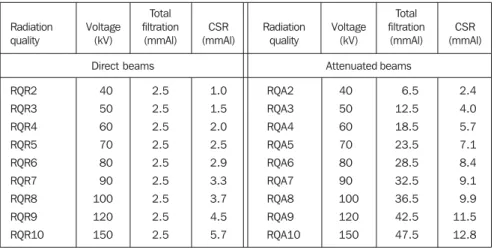
Table 1 shows the conventional radiology diagnosis beams characteristics in compliance with
Standard IEC 61267(15). All these standard radiation fields have been established in LCI-IPEN. The
qualities recommended for CT chambers calibration are the RQR9 e RQA9 qualities(16). Other
qualities will be utilized for calibration of other dosimeters used in diagnostic radiology and also for
a broader study on the pencil ionization chambers energy dependence.
Table 2 includes values obtained for first and second HVL, homogeneity coefficient (1st.
determined with a secondary Standard PTW 77334 chamber. Based on the HVL values the beams
effective energy values were determined(17).
Comparing the HVL obtained in LC-IPEN with those included in Table 1, it is possible to
observe several discordances between qualities. Presently this Standard is being reviewed and,
considering that some HVL values are discordant, probably the new version will bring new HVL
values. Considering that the LCI secondary standard system for these radiation qualities is certified
by the PTB, Germany primary laboratory, we have decided to follow the methodology hitherto
adopted in this laboratory: utilize the IEC 61267 voltage and added filtration parameters(15), without any adjustment, in an attempt to approach the HVL values established by this Standard.
Notwithstanding, correction factors were applied to calibration coefficients of the secondary
standard system for correcting HVL differences between LCI and PTB beams. It is important to
observe that the HVLs reported by the PTB calibration certificate also do not present a complete
concordance with Standard values.
There are some calibration methods for pencil ionization chambers and main difference
among them is the irradiated portion of the chamber sensitive length. Following the establishment
of standard radiation fields, two calibration methodologies were tested: with total irradiation of the
chamber sensitive length – the most usual calibration method for dosimeters in general; and with
partial irradiation of the chamber sensitive length, as recommended by the Standard IEC 61674(16). Only two radiation qualities recommended for pencil ionization chambers calibration were utilized
in these tests: RQR9 e RQA9.
In the majority of calibration procedures, the whole dosimeters sensitive area is irradiated.
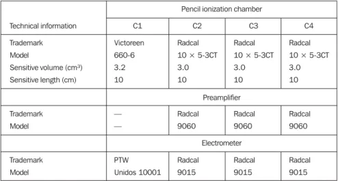
Also, it is possible to calibrate pencil ionization chambers in this way. Four pencil ionization
chambers described in Table 3 were calibrated by this method, utilizing the established
radiodiagnosis standard radiation fields. The chambers were positioned perpendicular to the
anode-cathode axis to avoid the anodic effect. The resulting calibration coefficients are shown in Table 4.
The second methodology adopted in the present study has been described by Bochud et al.(18). In their study, the researchers have concluded that results are better when 50% of the pencil
ionization chamber sensitive volume is irradiated during calibration. This is also the Standard IEC
61647 recommendation(16). The calibration procedure suggested by the present study is similar to the methodology with complete irradiation of the volume, with an additional collimation system
allowing the partial irradiation of the chamber under calibration.
For ensuring an accurate collimation, the collimation system must be positioned the nearest
possible to the chamber under calibration. This proximity, however, creates an undesirable effect:
an increase in scattered radiation contribution in the reading. This effect is still more accentuated
since the sensitive volume portion protected from the primary beam is not insensitive to the
scattered radiation. For determining the calibration coefficient, the introduction of a correction
factor for this effect is necessary. This correction is performed by determining a “residual reading”
in the ionization chamber that is a reading related to a null radiation field. This residual reading can
The four pencil ionization chambers described in Table 3 were calibrated according to this
second methodology. The resulting calibration coefficients also are included in Table 4. During
these calibration procedures, the movable collimation system was positioned at 6 mm from the
chambers under calibration which also were positioned perpendicular to the anode-cathode axis.
The horizontal opening of the field was fixed in 1.5 cm and the vertical opening ranged for allowing
different sensitive lengths irradiation.
Comparing the two methodologies results, one can observe that percent differences between
calibration coefficients obtained for RQR9 and RQA9 fields are 1.7%–4.6%. Bochud et al.(18) also have found deviations about 3.5% between calibration coefficients obtained through different
methodologies. The differences in calibration coefficients are resulting from absence of response
homogeneity along the chamber sensitive length, since in this type of ionization chamber there is
always a sensitiveness reduction in sensitive length ends.
Both coefficients from pencil ionization chamber sensitive volume total irradiation and
partial irradiation are correct. The difference is in what they express. When the chamber is
completely irradiated, an intermediate calibration coefficient is obtained as if the decrease in
sensitiveness in the extremity of the chamber was evenly distributed along the sensitive length. If in
the dosimetry practice the whole volume of the chamber was evenly irradiated, this coefficient
would be the most appropriate one. However, the majority of measurements are performed by
means of slices at maximum 1–2 cm thick, centered in the pencil ionization chamber. So the ends of
the chamber are much less exposed to radiation than its central region. Thus it is more
recommended to avoid a total irradiation of the chamber sensitive volume during calibration process
aiming at obtaining a calibration coefficient more compatible with the characteristics of the central
region of the chamber.
The combined standard uncertainties involved in all calibrations performed during this
project have been estimated according recommendations included in “Guia para a expressão da
incerteza de medição” (Guidance on expression of uncertainty in measurement
)
, of AssociaçãoBrasileira de Normas Técnicas (ABNT) (Brazilian Association of Technical Standards)(19,20),
considering the uncertainties involved in all parameter considered as relevant in the measurement
process. A 95% confidence interval (coverage factor (k) = 2) was considered.
CONCLUSION
The LCI is already qualified to deliver an adequate service for CT ionization chambers calibration
in Brazil. Two calibration methodologies have been tested and compared and a calibration
procedure has been elaborated applying the methodology considered as the most appropriate, with
irradiation of 50% of the sensitive volume of a pencil ionization chamber. As a result, the LCI has
complied in advance with the international recommendations from IAEA that only in 2005 had
defined the implementation of a calibration service for this type of chamber in its laboratory as a
Acknowledgements
The authors express their sincere thanks for the partial financial support by Fundação de
Amparo à Pesquisa do Estado de São Paulo (Fapesp) and Conselho Nacional de Desenvolvimento
Científico e Tecnológico (CNPq), Brazil.
REFERENCES
1. Shrimpton PC, Wall BF. The increasing importance of X-ray computed tomography as a source
of medical exposure. Radiat Prot Dosim 1995;57: 413–415.
2. Hart D, Wall BF. UK population dose from medical X-ray examinations. Eur J Radiol
2004;50:285–291.
3. Knoll GF. Radiation detection and measurement. 2nd ed. New York, NY: John Wiley & Sons,
1989.
4. Boag JW. Ionization chambers. In: Kase KR, Bjärngard BE, Attix FH, editors. The dosimetry
of ionizing radiation. Orlando, FL: Academic Press Inc., 1987;2:169–243.
5. Rajan KNG. Advanced medical radiation dosimetry. New Delhi: Prentice-Hall of India, 1992.
6. Attix FH. Introduction on radiological physics and radiation dosimetry. 2nd ed., New York,
NY: John Wiley & Sons, 1986.
7. Shope TB, Gagne RM, Johnson GC. A method for describing the doses delivered by
transmission X-ray computed tomography. Med Phys 1981;8:488–495.
8. Jucius RA, Kambic GX. Radiation dosimetry in computed tomography (CT). SPIE Proc.,
Application of Optical Instrumentation in Medicine VI 1977;127:286–295.
9. Nagel HD. Radiation exposure in computed tomography – fundamentals, influencing
parameters, dose assessment, optimization, scanner data, terminology. 2nd ed., Frankfurt: COCIR,
2000;chapt. 2, Fundamentals of CT dosimetry.
10. European Commission. European guidelines on quality criteria for computed tomography.
Luxembourg, 1997. (EUR 16262 EN).
11. McNitt-Gray MF. The AAPM/RSNA physics tutorial for residents: Topics in CT. Radiation
dose in CT. RadioGraphics 2002;22:1541–1553.
12. International Atomic Energy Agency. Calibration of dosimeters used in radiotherapy. Technical
Reports Series 374. Vienna: IAEA, 1994.
13. International Atomic Energy Agency. Calibration of radiation protection monitoring
instruments. Safety Reports Series 16. Vienna: IAEA, 2000.
14. Ibbott G. Report of the 11th Meeting of the SSDL Scientific Committee. SSDL Newsletter
2005;50:4–19.
15. International Electrotechnical Commission. Medical diagnostic X-ray equipment – radiation
conditions for use in determination of characteristics. IEC 61267. Geneva: IEC, 1994.
16. International Electrotechnical Commission. Medical electrical equipment - Dosimeters with
ionization chamber and/or semi-conductor detectors as used in X-ray diagnostic imaging. IEC
17. International Organization for Standardization. X and gamma reference radiation for calibrating
dosemeters and doseratemeters and for determining their response as a function of photon energy,
part 1: Radiation characteristics and production methods. ISO 4037-1. Geneva: ISO, 1996.
18. Bochud FO, Grecescu M, Valley JF. Calibration of ionization chambers in air kerma length.
Phys Med Biol 2001;46:2477–2487.
19. Associação Brasileira de Normas Técnicas; Instituto Nacional de Metrologia, Normatização e
Qualidade Industrial. Guia para a expressão da incerteza de medição. 3ª ed. Rio de Janeiro, RJ:
ABNT-INMN, 2003.
20. International Organization for Standardization. Guide to the expression of uncertainty in
CALIBRAÇÃO DAS CÂMARAS DE IONIZAÇÃO
Tabelas
Table 2 Characteristics of radiation beams established in LCI.
Radiation quality RQR2 RQR3 RQR4 RQR5 RQR6 RQR7 RQR8 RQR9 RQR10 RQA2 RQA3 RQA4 RQA5 RQA6 RQA7 RQA8 RQA9 First CSR (mmAl) 1.44 1.79 2.09 2.35 2.65 2.95 3.24 3.84 4.73 2.22 3.91 5.34 6.86 8.13 9.22 10.09 11.39 Second CSR (mmAl) 1.80 2.38 2.92 3.42 3.99 4.62 5.20 6.31 7.79 2.50 4.15 5.83 7.32 8.54 9.70 10.73 12.16 Homogeneity coefficient 0.80 0.75 0.72 0.69 0.66 0.64 0.62 0.61 0.61 0.89 0.94 0.92 0.94 0.95 0.95 0.94 0.94 Effective energy (keV) 25.10 27.15 28.80 30.15 31.65 33.05 34.40 37.05 40.75 29.50 37.30 43.25 49.40 54.75 59.70 63.95 71.15 Air kerma rate (mGy/min.) 13.79 24.06 35.35 47.17 60.39 74.51 89.81 121.80 175.19 5.39 3.39 3.03 3.40 3.99 4.87 5.76 7.93 Table 1 Radiodiagnosis qualities according to standard IEC 61267(15).
RQR2 RQR3 RQR4 RQR5 RQR6 RQR7 RQR8 RQR9 RQR10 40 50 60 70 80 90 100 120 150 2.5 2.5 2.5 2.5 2.5 2.5 2.5 2.5 2.5 1.0 1.5 2.0 2.5 2.9 3.3 3.7 4.5 5.7 RQA2 RQA3 RQA4 RQA5 RQA6 RQA7 RQA8 RQA9 RQA10 40 50 60 70 80 90 100 120 150 6.5 12.5 18.5 23.5 28.5 32.5 36.5 42.5 47.5 2.4 4.0 5.7 7.1 8.4 9.1 9.9 11.5 12.8 Radiation quality Voltage (kV) Total filtration (mmAl) CSR (mmAl) Radiation quality Voltage (kV) Total filtration (mmAl) CSR (mmAl)
Direct beams Attenuated beams
Table 3 Technical information on pencil ionization chambers utilized in this study.
Technical information
Trademark Model
Sensitive volume (cm³) Sensitive length (cm)
Trademark Model Trademark Model C1 Victoreen 660-6 3.2 10 — — PTW Unidos 10001 C2 Radcal 10 × 5-3CT 3.0 10 Radcal 9060 Radcal 9015 C3 Radcal 10 × 5-3CT 3.0 10 Radcal 9060 Radcal 9015 C4 Radcal 10 × 5-3CT 3.0 10 Radcal 9060 Radcal 9015 Pencil ionization chamber
Preamplifier
Electrometer
Table 4 Calibration coefficients obtained for four pencil ionization chambers described in Table 3, in stan-dard radiation fields RQR9 and RQA9, for two different calibration methodologies: with total irradiation and with partial (50%) irradiation of the chamber sensitive volume under calibration.
Radiation quality
RQR9 RQA9
Standard combined uncertainty
RQR9 RQA9
Standard combined uncertainty
Total irradiation of the chamber sensitive volume
Irradiação parcial (50%) do volume sensível C1
(×108 Gy/C)