C
OMPOSITE
P
LATE
G
IRDER
B
RIDGES
A State-of-the-Art Report of UK Practice
J
OSÉP
EDROV
ILASB
OAS DEM
ONTALVÃOF
ERNANDESDissertation submitted for the partial fullfillement of the requirements to the degree of MASTER’S IN CIVIL ENGINEERING —SPECIALISATION IN STRUCTURES
Professor Dr. José Miguel de Freitas Castro
Dr. Ricardo Nuno Tavares Teixeira
Tel. +351-22-508 1901 Fax +351-22-508 1446 [email protected]
Editado por
FACULDADE DE ENGENHARIA DA UNIVERSIDADE DO PORTO Rua Dr. Roberto Frias
4200-465 PORTO Portugal Tel. +351-22-508 1400 Fax +351-22-508 1440 [email protected] http://www.fe.up.pt
Reproduções parciais deste documento serão autorizadas na condição que seja mencionado o Autor e feita referência a Mestrado Integrado em Engenharia Civil - 2015/2016 - Departamento de Engenharia Civil, Faculdade de Engenharia da Universidade do Porto, Porto, Portugal, 2016.
As opiniões e informações incluídas neste documento representam unicamente o ponto de vista do respetivo Autor, não podendo o Editor aceitar qualquer responsabilidade legal ou outra em relação a erros ou omissões que possam existir.
Este documento foi produzido a partir de versão eletrónica fornecida pelo respetivo Autor.
To João and Tiago, For the infinite joy they bring.
To Sofia Marques da Silva, For seeding the will.
Everything should be made as simple as possible, but no simpler. Albert Einstein
ACKNOWLEDGMENTS
The author would like to thank his employer WSP | Parsons Brinckerhoff in the persons of David Gulick, Andrew Porter, and especially Kelly Croke for their sponsorship in the undertaking of this work.
To Professor José Miguel Castro for his willingness to tutor this dissertation written at a distance regardless of the constraints, and for his review and constructive criticism of the work.
A special thanks to Dr. Ricardo Teixeira, tutor, colleague and friend. For his unflinching support, review of the text, and especially for the long hours of discussion about any subject in structural engineering.
To Tony Harris, Head of Discipline – Bridges at WSP | Parsons Brinckerhoff, for his valuable comments and insights.
To my colleagues and friends Tom Corcoran and Stephen Heaney for their comments and long hours of fruitful discussion.
Finally, to acknowledge Elfyn Williams at Welsh Government for providing the data on existing road bridges in Wales and Richard Stonehouse at Mabey Bridge for the data on fabrication costs used in Chapter 2.
ABSTRACT
The United Kingdom has a rich history in the design and construction of steel bridges. This is owed in great part to having been the birthplace of the Industrial Revolution, when advances in scientific knowledge and manufacture process enabled the economic production of large quantities of steel. The invention of the steam-engine train and the construction of railways that followed provided a fertile ground for engineers of the time to continually experiment with the new material. In the following century the construction of bridges would reach spans unimaginable until then. With the rise of the automobile in the 20th century and the expansion of motorways in post-war Europe the ground was provided for the construction of many new bridges. It was in this context that steel-concrete composite bridges first made their appearance in the 1960’s. Since then composite bridges underwent continuous development to their present types. Since then composite bridges evolved continuously to the deck types that can be seen today.
This dissertation intends to present a review of the state-of-the-art of UK practice in the analysis and design of steel-concrete composite bridges. Following an historical background to the evolution of steel bridges an overview of the presence of composite bridges within existing road bridges in service is set out. Typical deck cross-sections in use in the UK construction industry and their respective preferred range of application are presented, as well as information on plate girder fabrication costs. The methods used in practice today for the global analysis of composite bridge decks are addressed in following. The design actions and the rules for combinations of actions in current design codes (the Eurocodes) that define ultimate and serviceability limit states are presented. The quantification of time dependant properties of concrete and a general view of the analysis models at the disposal of practising engineers are provided.
A review of the design of composite cross-sections follows, starting with the cross-section classification process and the explanation of its consequences in the cross-section resistances. The verification of cross-section resistances to bending flexure, vertical shear force, combined bending and vertical shear force, and longitudinal shear force for ultimate limit states is presented in detail. The importance of serviceability limit state checks is highlighted. Verifications of stress limitations in structural steelwork, reinforcing steel and concrete are presented as well as the control of concrete cracking by limiting crack widths.
The presentation of a case study of the preliminary design of a steel-concrete composite viaduct in Wales demonstrates how the subjects covered all come together in the design of a bridge structure. It is shown how the brief requirements and the site constraints to be addressed dictated the choice of the type of superstructure, in this case a solution typical of the UK which is the ladder deck. The design actions to be considered and the type of model chosen for the global analysis of the deck are then presented. These are followed by the validation of the design by means of cross-section verifications for ultimate limit states. A summary of the merits of the proposed solution and its economy of design concludes the dissertation.
RESUMO
O Reino Unido tem uma história rica no projecto e construção de pontes em aço. Tal deve-se em grande parte a ter sido o berço da Revolução Industrial, quando progressos no conhecimento científico e nos processos de fabrico possibilitaram a produção económica de aço em grandes quantidades. A invenção do comboio a vapor e a construção de ferrovias que se seguiu proporcionaram terreno fértil para os engenheiros da época experimentarem o novo material, com a construção de pontes no século seguinte a atingir vãos até então inimagináveis. Com o surgir do automóvel no século XX e a expansão da rede de autoestradas no pós-guerra proporcionou-se a construção de grande número de novas pontes. Foi neste contexto que as pontes mistas aço-betão fizeram a sua primeira aparição nos anos sessenta. Desde então as pontes mistas evoluíram continuamente até às tipologias de tabuleiros que se podem ver nos dias de hoje.
Esta dissertação pretende apresentar uma revisão do estado-da-arte da prática no Reino Unido da análise e projecto de pontes mistas aço-betão. Após um enquadramento histórico da evolução das pontes em aço uma visão geral da presença das pontes mistas entre as pontes rodoviárias em service é estabelecida. As secções transversais típicas em uso na indústria da construção do Reino Unido e o seu respectivo campo de aplicação preferencial são apresentadas, bem como informação sobre custos de fabricação de vigas de alma cheia.
Os métodos usados hoje na análise global de tabuleiros de pontes mistas serão abordados de seguida. As acções de cálculo e as regras para combinações de acções dos códigos de projecto actuais (os Eurocódigos) que definem os estados limite último e de serviço são apresentadas. A quantificação das propriedades diferidas do betão e uma visão geral dos modelos de análise à disposição do engenheiro são fornecidas.
Segue-se uma revisão do projecto de secções mistas, com início no processo de classificação de secções e a explicação das suas consequências para a resistência da secção. A verificação das resistências à flexão, ao esforço transverso, à combinação entre flexão e esforço transverso, e ao esforço rasante é apresentada detalhadamente. A importância da verificação de estados limite de service é sublinhada. As verificações de limitação de tensões no aço estrutural, nas armaduras e no betão são apresentadas bem como o controlo de fissuração do betão pela limitação da abertura de fendas.
A apresentação de um caso de estudo do estudo prévio de um viaduto misto aço-betão em Gales demonstra como os temas cobertos se combinam no projecto de uma ponte. É mostrado como os requisitos do caderno de encargos e os condicionantes locais a abordar ditaram a escolha do tipo de superestrutura, neste caso uma solução típica do Reino Unido que é o tabuleiro bi-viga com carlingas. As acções de cálculo a considerar e o modelo adoptado para a análise global do tabuleiro são apresentados. Segue-se a validação da solução através das verificações da secção para o estado limite último. Um resumo das mais-valias da solução proposta e da economia do seu projecto conclui a dissertação.
TABLE OF CONTENTS ACKNOWLEDGEMENTS ... i ABSTRACT ... iii RESUMO ... v
1 INTRODUCTION ... 1
1.1.GENERAL CONSIDERATIONS ... 1 1.2.HISTORICAL BACKGROUND ... 2 1.3.GENERAL OBJECTIVES ... 2 1.4.DISSERTATION CONTENTS ... 32 STATE-OF-THE-ART IN THE UK ... 5
2.1.HISTORICAL OVERVIEW OF STEEL BRIDGES IN BRITAIN ... 5
2.1.1. PIONEERS OF THE GEORGIAN ERA ... 5
2.1.2. VICTORIAN RAILWAY ENGINEERING ... 10
2.1.3. EDWARDIAN ENGINEERING AND THE ARRIVAL OF STEEL ... 15
2.1.4. BRIDGE ENGINEERING IN THE INTERWAR PERIOD ... 18
2.1.5. EVOLUTION OF BRIDGES FROM THE POST-WAR ERA TO PRESENT DAY ... 20
2.2.COMPOSITE BRIDGES WITHIN ROAD NETWORKS IN WALES ... 29
2.2.1. EXISTING BRIDGE DISTRIBUTION BY CONSTRUCTION TYPE ... 29
2.2.2. EXISTING BRIDGE DISTRIBUTION BY SPAN RANGE ... 30
2.2.3. EXISTING BRIDGE DISTRIBUTION BY CONSTRUCTION DATE ... 30
2.2.4. CONSTRUCTION TYPE IN RELATION TO SPAN RANGE ... 31
2.3.TYPICAL COMPOSITE BRIDGE DECKS FROM UKPRACTICE ... 32
2.3.1. MULTI GIRDER BRIDGE DECK CROSS SECTIONS ... 33
2.3.2. TWIN GIRDER BRIDGE DECK CROSS SECTIONS ... 34
2.3.3. MULTIPLE COMPACT BOX BRIDGE DECK CROSS SECTIONS ... 35
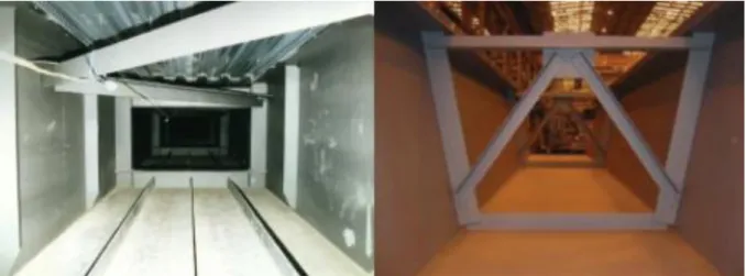
2.3.4. OPEN TOP TRAPEZOIDAL BOX BRIDGE DECK CROSS SECTIONS ... 36
2.4.ECONOMY AND FABRICATION COSTS ... 38
3 GLOBAL ANALYSIS OF COMPOSITE DECKS ... 41
3.1.1. DEAD LOADS – SELF-WEIGHT OF STRUCTURE ... 42
3.1.2. SUPERIMPOSED DEAD LOADS - SELF-WEIGHT OF NON-STRUCTURAL ELEMENTS ... 43
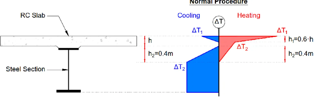
3.1.3. THERMAL ACTIONS – TEMPERATURE DIFFERENCE COMPONENTS ... 44
3.1.4. ROAD TRAFFIC ACTIONS ON BRIDGES ... 45
3.1.4.1. Models of Road Traffic Actions ... 45
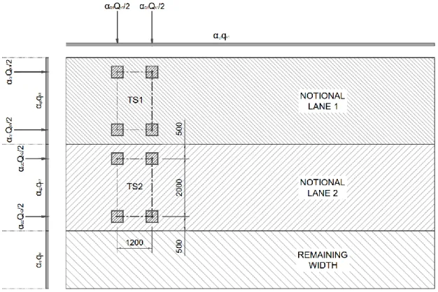
3.1.4.2. Division of the Carriageway and Load Application ... 46
3.1.4.3. Load Model 1 ... 48
3.1.4.4. Load Model 2 ... 50
3.1.4.5. Load Model 3 ... 50
3.1.4.6. Load Model 4 ... 53
3.1.4.7. Loading on Footways and Cycletracks ... 53
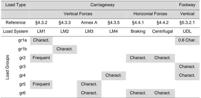
3.1.4.8. Groups of Traffic Loads ... 53
3.2.COMBINATIONS OF ACTIONS FOR ROAD BRIDGES ... 54
3.2.1. LIMIT STATE DESIGN TO THE PARTIAL FACTOR METHOD... 54
3.2.2. ULTIMATE LIMIT STATE COMBINATIONS ... 55
3.2.3. SERVICEABILITY LIMIT STATE COMBINATIONS ... 56
3.2.4. PARTIAL SAFETY FACTORS FOR ACTIONS ... 58
3.3.TIME DEPENDENT PROPERTIES OF CONCRETE ... 60
3.3.1. SHRINKAGE OF CONCRETE ... 60
3.3.2. CONCRETE CREEP ... 63
3.4.STRUCTURAL ANALYSIS OF COMPOSITE DECKS ... 65
3.4.1. STRUCTURAL MODELLING FOR ANALYSIS ... 65
3.4.2. STRUCTURAL STABILITY ... 67
3.4.3. EFFECTIVE WIDTH OF FLANGES FOR SHEAR LAG ... 68
3.4.4. MODULAR RATIOS FOR CONCRETE ... 71
3.4.5. EFFECTS OF CRACKING OF CONCRETE... 72
3.4.6. PRIMARY AND SECONDARY EFFECTS OF CONCRETE SHRINKAGE ... 73
4 DESIGN OF COMPOSITE CROSS-SECTIONS ... 81
4.1.CLASSIFICATION OF CROSS-SECTIONS ... 81
4.1.1. DETERMINATION OF THE CROSS-SECTION CLASS ... 82
4.1.2. EFFECTIVE SECTION OF CLASS 4 CROSS-SECTIONS ... 83
4.2.CROSS-SECTION VERIFICATION FOR ULTIMATE LIMIT STATES ... 86
4.2.1.1. Plastic Resistance Moment ... 86
4.2.1.2. Non-Linear Resistance Moment ... 88
4.2.1.3. Elastic Resistance Moment ... 90
4.2.2. CROSS SECTION RESISTANCE TO VERTICAL SHEAR ... 92
4.2.2.1. Plastic Resistance to Vertical Shear ... 93
4.2.2.2. Shear Buckling Resistance to Vertical Shear ... 94
4.2.2.3. Bending and Vertical Shear Interaction ... 98
4.2.3. CROSS SECTION RESISTANCE TO LONGITUDINAL SHEAR ... 101
4.2.3.1. Longitudinal Shear Force for Beams in Bridges ... 102
4.2.3.2. Design Resistance of Headed Stud Connectors ... 105
4.2.3.3. Detailing of the Shear Connection ... 106
4.3.CROSS-SECTION VERIFICATION FOR SERVICEABILITY LIMIT STATES ... 108
4.3.1. STRESS LIMITATIONS FOR BRIDGES ... 108
4.3.1.1. Concrete Compressive Stress Limits ... 109
4.3.1.2. Reinforcing Steel Tensile Stress Limits ... 109
4.3.1.3. Steelwork Stress Limits ... 110
4.3.1.4. Limitation of Longitudinal Shear Force of Connectors ... 111
4.3.2. WEB BREATHING ... 111
4.3.3. CRACKING OF CONCRETE ... 112
4.3.3.1. Minimum Reinforcement for Restraint of Imposed Deformations ... 113
4.3.3.2. Control of Cracking Due to Direct Loading ... 114
5 CASE STUDY – THE RIVER SEIONT VIADUCT ... 117
5.1.INTRODUCTION AND BACKGROUND ... 117
5.1.1. THE A487 CAERNARFON TO BONTNEWYDD BYPASS ... 117
5.1.2. OPTIONS DEVELOPMENT FOR THE RIVER SEIONT VIADUCT ... 119
5.2.PROPOSED STRUCTURE ... 121
5.2.1. DESCRIPTION OF STRUCTURE AND DESIGN WORKING LIFE ... 122
5.2.2. DECK CROSS-SECTION OF THE VIADUCT ... 123
5.2.3. MATERIALS ... 125
5.3.DESIGN ACTIONS AND COMBINATIONS ... 125
5.3.1. PERMANENT ACTIONS ... 125
5.3.2. SHRINKAGE ... 126
5.3.4. ROAD TRAFFIC ACTIONS ... 127
5.3.5. COMBINATIONS OF ACTIONS ... 129
5.4.GLOBAL ANALYSIS OF THE VIADUCT ... 130
5.4.1. EFFECTIVE WIDTH OF FLANGES FOR SHEAR LAG ... 130
5.4.2. MODULAR RATIOS FOR CONCRETE ... 130
5.4.3. EFFECTS OF CRACKING OF CONCRETE... 132
5.4.4. STRUCTURAL ANALYSIS MODEL ... 132
5.4.5. LINEAR ELASTIC ANALYSIS ... 134
5.5.CROSS-SECTION VERIFICATION AT ULS ... 137
5.5.1. BENDING RESISTANCE OF THE SPAN CROSS-SECTION ... 137
5.5.2. BENDING RESISTANCE OF THE PIER CROSS-SECTION ... 139
5.5.3. SHEAR RESISTANCE OF PIER CROSS-SECTION ... 143
5.5.4. BENDING AND VERTICAL SHEAR INTERACTION OF PIER CROSS-SECTION ... 145
5.6.MATERIAL QUANTITIES AND STEEL CONSUMPTION ... 147
6 CONCLUSIONS ... 149
6.1.CLOSING REMARKS ... 149
TABLE OF FIGURES
Fig. 2.1 – The Iron Rolling Mill, Adolph Von Menzel 1875 (from Google Art Project) ... 6
Fig. 2.2 – The Cast Iron Bridge near Coalbrookdale, painting by William Williams, 1780 (from bbc.co.uk) ... 7
Fig. 2.3 – The Iron Bridge over the River Severn at Buildwas (from Shrewsbury Museum Service) ... 8
Fig. 2.4 – The Pontcysyllte Aqueduct (from whc.unesco.org) ... 9
Fig. 2.5 – The Menai Straight Bridge (from wikipedia.org) ... 10
Fig. 2.6 – The Clifton Suspension Bridge (from wikipedia.org) ... 11
Fig. 2.7 – The Windsor Railway Bridge (from wikipedia.org) ... 12
Fig. 2.8 – The Royal Albert Bridge (from bbc.co.uk) ... 13
Fig. 2.9 – The Britannia Bridge (from denbighshirearchives.wordpress.com) ... 14
Fig. 2.10 – The Forth Bridge (from wikipedia.org) ... 16
Fig. 2.11 – The Tower Bridge (from bbc.co.uk) ... 16
Fig. 2.12 – Connel Bridge (from rcahms.gov.uk) ... 17
Fig. 2.13 – Queen Alexandra Bridge under construction (from urbanglasgow.co.uk) ... 18
Fig. 2.14 – Tyne Bridge (from wikipedia.org) ... 19
Fig. 2.15 – Billingham Bridge (from geograph.co.uk) ... 19
Fig. 2.16 – Pelham Bridge (from geograph.co.uk) ... 20
Fig. 2.17 – First Severn Crossing (from severnbridge.co.uk) ... 21
Fig. 2.18 – Tay Estuary Road Bridge (from songofthepaddle.co.uk) ... 21
Fig. 2.19 – Tinsley Viaduct (from sabre-roads.co.uk) ... 22
Fig. 2.20 – Raith Bridge (James Brown, 2010) ... 23
Fig. 2.21 – Cantilever construction of the Cleddau Bridge (Robert Matera-Byford, 2009) ... 23
Fig. 2.22 – Saltings Viaduct (from SWTRA) ... 24
Fig. 2.23 – Friarton Bridge (from geograph.org.uk)... 25
Fig. 2.24 – Humber Bridge under construction (from geograph.org.uk) ... 26
Fig. 2.25 – Queen Elizabeth II Bridge (from sevenoakschronicle.co.uk) ... 26
Fig. 2.26 – Hulme Bridge (from wikipedia.org) ... 27
Fig. 2.27 – River Usk Bridge (from newsteelconstruction.com) ... 28
Fig. 2.28 – River Usk Bridge under construction (from mabeybridge.com) ... 28
Fig. 2.29 – Existing bridge distribution by construction type ... 29
Fig. 2.30 – Existing bridge distribution by span range ... 30
Fig. 2.32 – Bridge construction type in relation to span range ... 32
Fig. 2.33 – Multi girder deck cross section (from Steel Detailers Manual, Blackwell Science, 2002) ... 33
Fig. 2.34 – Twin girder deck with transverse girders cross section (from Steel Detailers Manual, Blackwell Science, 2002) ... 34
Fig. 2.35 – Multiple closed box deck cross section (from Steel Detailers Manual, Blackwell Science, 2002) ... 36
Fig. 2.36 – Open top trapezoidal box deck cross section (from Steel Detailers Manual, Blackwell Science, 2002)... 37
Fig. 2.37 – Open top box section with and without longitudinal stiffening (from Guidance Notes on Best Practice in Steel Bridge Construction, SCI, 2010) ... 37
Fig. 3.1 – Typical cross section of a single carriageway road bridge... 43
Fig. 3.2 – Normal procedure for the definition of the temperature difference component. ... 44
Fig. 3.3 – Simplified procedure for the definition of the temperature difference component. ... 44
Fig. 3.4 – Examples of carriageway widths w to consider (from Designers Guide to Eurocode 1, Thomas Telford, 2010) ... 46
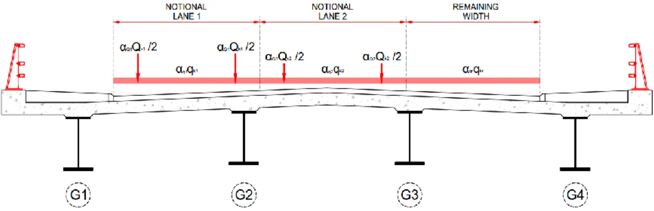
Fig. 3.5 – Possible notional lane definition for worst effects from LM1 on girder G1. ... 47
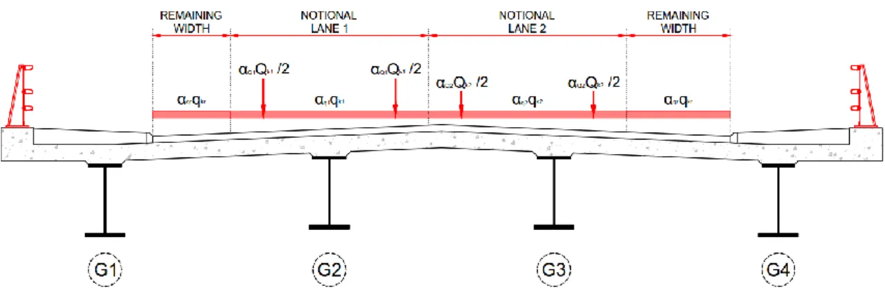
Fig. 3.6 – Possible notional lane definition for worst effects from LM1 on girder G2. ... 48
Fig. 3.7 – Longitudinal and plan application of Load Model LM1 as per UKNA of EN1990... 49
Fig. 3.8 – Load Model LM2 consider (from Designers Guide to Eurocode 1, Thomas Telford, 2010) . 50 Fig. 3.9 – Configuration of SV80 vehicle (from UK National Annex to EN 1991-2:2003, BSI, 2008) ... 51
Fig. 3.10 – Configuration of SOV-250 vehicle (from UK National Annex to EN 1991-2:2003, BSI, 2008) ... 51
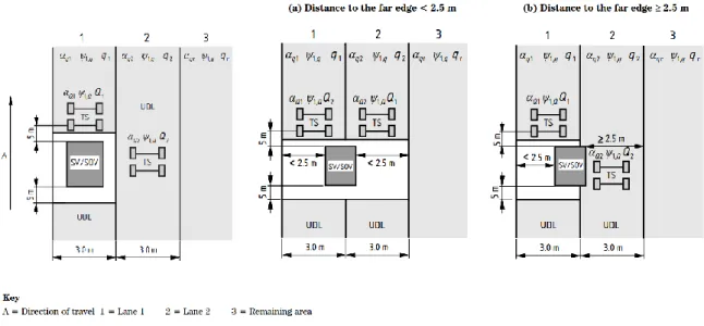
Fig. 3.11 – Application of SV or SOV vehicle with Load Model 1 (from UK National Annex to EN 1991-2:2003, BSI, 2008) ... 52
Fig. 3.12 – Time dependant evolution of concrete shrinkage strain (h0=250mm, ts=1d, RH=80%) ... 62
Fig. 3.13 – Development of creep coefficient over time (h0=250mm, fck=35MPa, RH=80%) ... 64
Fig. 3.14 – Example of finite element grillage model ... 66
Fig. 3.15 – Example of finite element hybrid model ... 66
Fig. 3.16 – Example of finite element shell model... 67
Fig. 3.17 – Bending stress distribution in wide flanges due to shear lag effect. ... 69
Fig. 3.18 – Equivalent span Le for continuous girders (from EN1994-2, BSI, 2010). ... 70
Fig. 3.19 – Non-uniform longitudinal stress at mid-plane of the concrete flange of a hybrid model. .... 70
Fig. 3.20 – Cracked regions over an internal support as per the simplified method. ... 73
Fig. 3.21 – Eccentricity between slab mid-plane and centroid of composite section ... 74
Fig. 3.23 – Bending moment due to shrinkage effects in a simply supported composite beam. ... 75
Fig. 3.24 – Uncracked section stresses due to primary shrinkage effects. ... 75
Fig. 3.25 – Structural analysis diagram of a continuous uncracked composite beam. ... 76
Fig. 3.26 – Bending moments due to shrinkage effects in a continuous uncracked composite beam. 76 Fig. 3.27 – Uncracked section stresses due to primary and secondary shrinkage effects. ... 76
Fig. 3.28 – Structural analysis diagram of a continuous composite beam with cracked regions. ... 77
Fig. 3.29 – Bending moments due to shrinkage effects in a composite beam with cracked regions. .. 77
Fig. 3.30 – Cracked section stresses due to secondary shrinkage effects. ... 78
Fig. 4.1 – Effective web of Class 4 cross-section. ... 85
Fig. 4.2 – Stress distribution for plastic sagging resistance moment. ... 87
Fig. 4.3 – Stress distribution for plastic hogging resistance moment. ... 87
Fig. 4.4 – Stress distribution on effective section for plastic hogging resistance moment. ... 88
Fig. 4.5 – Stress-strain diagrams for non-linear resistance model. ... 89
Fig. 4.6 – Stress distribution for elasto-plastic sagging resistance moment. ... 90
Fig. 4.7 – Cumulative stresses for calculation of the elastic resistance moment. ... 91
Fig. 4.8 – Pure shear stress state in a web plate (from Design of Plated Structures, ECCS, 2010) .... 94
Fig. 4.9 – Post-critical stresses in a web plate (from Design of Plated Structures, ECCS, 2010) ... 94
Fig. 4.10 – Mechanical model of the rotated stress field (from Commentary and Worked Examples to EN1993-1-5, ECCS, 2007) ... 95
Fig. 4.11 – Reduction curves for shear buckling and critical shear stress ... 98
Fig. 4.12 – Plastic stress distribution modified by the effect of vertical shear (from EN 1994-2:2005, BSI, 2008) ... 99
Fig. 4.13 – Region to consider the interaction of bending moment and shear force (from Design of Plated Structures, ECCS, 2010)... 101
Fig. 4.14 – Definition of an inelastic length for the determination of longitudinal shear force (from EN 1994-2:2005, BSI, 2008) ... 103
Fig. 4.15 – Variation of normal force in the concrete slab with bending moment (from Designers Guide to EN1994-2, Thomas Telford, 2006) ... 103
Fig. 4.16 – Determination of the longitudinal shear force from primary shrinkage at the end of a beam (from Designers Guide to EN1994-2, Thomas Telford, 2006) ... 104
Fig. 4.17 – Typical potential surfaces of shear failure (from EN 1994-2:2005, BSI, 2008) ... 107
Fig. 5.1 – A487 Caernarfon to Bontnewydd Bypass Preferred Routes ... 118
Fig. 5.2 – Horizontal alignment of the A487 over River Seiont ... 119
Fig. 5.3 – Plan of River Seiont Viaduct. ... 122
Fig. 5.5 – A487 Carriageway over River Seiont Viaduct ... 123
Fig. 5.6 – Typical cross section of River Seiont Viaduct ... 124
Fig. 5.7 – Elements of the deck cross-section of River Seiont Viaduct ... 126
Fig. 5.8 – Notional lanes for most adverse effects on left girder ... 128
Fig. 5.9 – Notional lanes for most adverse effects on right girder ... 129
Fig. 5.10 – Notional cross-sections of spans 2 and 3. ... 132
Fig. 5.11 – Three-dimensional line beam model of River Seiont Viaduct. ... 133
Fig. 5.12 – Bending moment diagram due to effects of permanent actions. ... 134
Fig. 5.13 – Bending moment diagrams due to effects of shrinkage. ... 134
Fig. 5.14 – Bending moment envelopes due to effects of road traffic actions. ... 135
Fig. 5.15 – Bending moment diagram due to effects of temperature difference. ... 135
Fig. 5.16 – ULS bending moment envelope. ... 136
Fig. 5.17 – ULS shear force envelope. ... 136
Fig. 5.18 – Plastic stress distribution on effective Class 2 cross-section. ... 141
TABLE OF TABLES
Table 2.1 - Typical distribution of work hours to girder weight for UK steel fabrication. ... 38
Table 3.1 - Number and width notional lanes ... 47
Table 3.2 - Load Model 1 characteristic values and UK National Annex adjustment factors. ... 48
Table 3.3 - Characteristic values of the multi-component action of group traffic loads. ... 54
Table 3.4 - Partial factors for design values of actions (STR/GEO) Set B (from EN1990) ... 58
Table 3.5 - Recommended values of ψ factors for road bridges (from EN1990) ... 59
Table 3.6 - Basic combinations at ULS (STR/GEO) for analysis of road bridges decks. ... 60
Table 4.1 - Maximum width-to-thickness ratios for compression parts as per Table 5.2 of EN1993-1-1. ... 82
Table 4.2 - Shear buckling factor as per Table 5.1 of EN1993-1-5. ... 96
Table 4.3 - Recommended values of wmax as per Table 7.101N of EN1992-2. ... 112
Table 5.1 – Structural steelwork grades used in the River Seiont Viaduct. ... 124
Table 5.2 – Structural steelwork grades used in the River Seiont Viaduct. ... 125
Table 5.3 – Concrete grades used in the River Seiont Viaduct. ... 125
Table 5.4 – Permanent actions on River Seiont Viaduct. ... 126
Table 5.5 – Combinations of actions considered for preliminary design... 129
Table 5.6 – Effective widths of the concrete flange... 130
Table 5.7 – Axial forces on the steel section elements. ... 137
Table 5.8 – Axial forces and lever arms of the composite cross-section elements. ... 138
Table 5.9 – Axial forces on cross-section elements for plastic stress distribution. ... 139
Table 5.10 – Axial forces on the cross-section web for plastic stress distribution. ... 140
Table 5.11 – Axial forces and lever arms of the effective cross-section elements. ... 142
Table 5.12 – Axial forces and lever arms considering reduced steel strength of web. ... 147
1
INTRODUCTION
1.1. GENERAL CONSIDERATIONS
Since the dawn of Humanity we have tried to better our lives by producing tools and utensils to ease our chores and by building shelters where Nature provided few or any. The birth of ancient civilisations spawned complex societies where the separation of Humans from the natural environment would become the norm. The urbanisation process and its increased concentration of human populations would precipitate the desire of the ruling political and religious elites for monumental architectural works to affirm authority, but most importantly, would spark the need for engineering works such as aqueducts, bridges, canals and roads that enabled the new social fabric to exist.
The evolution of bridge construction has followed a parallel path with the development and transitions experienced by Human societies throughout history. The expansion of early empires brought about a dissemination of engineering works around the globe. However, the slow evolution of science and technology in the centuries to follow meant that construction technology had not changed greatly by the Middle Ages. With the advent of the Renaissance history would be proppelled into the Modern Age, with the seafaring discovery voyages bringing about a global world. The new-found prosperity enabled master builders to strive for bolder designs, but it would not be until the scientific revolution of the Enlightnment that bridge engineering would break away from its past.
With the Industrial Revolution an unseen rate of technological progress pushed the boundaries of possibility to new heights. There were new scientific methods to analyse and design bridges, new materials to be used in their construction, and new machinery with which to build them. The construction of roads and railways in the 1800’s was a fertile ground for the development of modern bridge engineering, with the rise of steel as the material of choice for major bridges. The progress made during the 19th century is best put in context by the evolution of main span length. When the Pont de Vieille-Brioude collapsed in1822 its 54m masonry arch span was thought to have been the World’s largest for the last 300 years. The steel arch of Eiffel’s Garabit Viaduct on the Clermont-Ferrand to Béziers railway had a record span of 165m when completed in 1886.
Since it was first introduced in the late 1800’s steel remained the material of choice for the construction of long span bridges throughout the 20th century. The development of reinforced concrete at the turn of the century and that of prestressed concrete in postwar presented two new materials that proved to be very competitive for short and medium spans. The higher cost of steel only decks meant that these would be better suited for long spans where the added weight of concrete was detrimental. From the 1960’s onwards the development of steel-concrete composite decks again turned the tables on prestressed concrete by providing an economical alternative to for medium span ranges. By providing steel girders and a reinforced concrete deck slab with an interface connection that enables
the composite behaviour of the cross-section an efficient structural type was created. Where speed of construction with minimal traffic disruption is required composite bridges are today challenged only by precast concrete solutions.
The advances in the last 30 years in automated fabrication processes and in construction equipment have rendered composite bridges as high-quality solutions from a technological and economical perspective. Innovative designs making use of high strength steels in the flanges of hybrid girders and cross-sections with double composite action are expanding the optimal range of application of composite bridges. Today’s trends of off-site construction for quality control, the constraints from existing road and rail traffic, the short programmes for delivery of major engineering works schemes, all seem to point to a greater relevance of composite bridges in the near future.
1.2. HISTORICAL BACKGROUND
With a strong tradition in the construction of steel bridges the United Kingdom was naturally among the pioneering nations were composite bridge construction was introduced. The expansion of the motorway network during the 1950’s and 1960’s provided the opportunity for composite bridges to be brought to the fore.
After an initial process of experimentation with the new bridge type designers grew more and more confident in its possibilities and devised designs that were ever more innovative and bold. The fast rate of innovation that steel bridge construction was experiencing in the early 1970’s would suffer a serious setback due to a set of spectacular accidents with box girder bridges. The loss of public confidence together with new regulations that imposed tighter requirements on fabrication would render steel construction less competitive than before.
The process of standardisation of construction regulations launched by the European Commission led to abundant investigation on the behaviour of steel and composite structures. Contributions from practising engineers and academics from across the continent were included in new design standards: the Eurocodes. With previous shortcomings in theoretical models resolved and with the advances in computer structural analysis software of the past three decades practicing engineers have had the know-how and the means to innovate.
1.3. GENERAL OBJECTIVES
The purpose of this work is to provide an overview of the current practice and trends in the design of composite bridges in the United Kingdom. In order to achieve this, an insight into the historical context in which steel bridges appeared in Britain and their evolution until the present day provides the background that lead to the composite bridges designed and built in recent decades.
An outline of the actions and design situations prescribed by current standards as the functional requirements for which bridges are designed in the UK, together with a review of the models applicable to the analysis of bridge superstructures and commentary on the design and verification of cross-sections are intended to provide a broad view of the state-of-the-art of composite bridge design.
1.4. DISSERTATION CONTENTS
Following a brief introduction with the background and objectives of this dissertation a review of the state-of-the-art of composite bridges in the United Kingdom is presented. The next chapter will provide an overview of the standards defining the actions on bridges and an outline of methodologies for the global analysis of composite decks from the perspective of the practising engineer. An overview of the design verifications of member resistances as well as of serviceability criteria will then be addressed. A case study presentation of the preliminary design of a highway viaduct in Wales will provide justification for the choice of a composite solution as the best suited to the brief’s requirements. The closing remarks present the lessons learned and main conclusions as well as possible future developments.
The contents of this dissertation are presented over five chapters.
In Chapter 2 the historical evolution of steel bridges in Britain since the Industrial Revolution to present day is described, followed by a quantitative analysis of existing road bridges in Wales to put in context composite bridges in terms of market share and span range. The types of composite decks most commonly used in the construction of bridges in the UK are then presented and their range of application discussed. The chapter closes with a commentary on the fabrication costs of plated girders and considerations for economic design.
Chapter 3 covers the global analysis of composite bridge decks. It starts by presenting an overview of the actions prescribed by the Eurocodes for the design of bridges, and proceeds to illustrate the rules for combinations of actions that define design situations for serviceability and ultimate limit states. The modifications enforced by the UK National Annexes are commented upon. An outline of the modelling approaches at the disposal of designers for the analysis of composite decks is presented, along with their strong points and limitations. To finalise, the effects of concrete cracking and shrinkage on composite structures are explained.
In Chapter 4 the design of composite cross-sections is covered in detail. The chapter begins by presenting the cross-section classification process and explaining its repercussions on the cross-section resistance. The concept of effective cross-sections is introduced. In following, the verifications of cross-section resistances for ultimate limit states are developed upon, and the resistances to bending flexure, vertical shear and longitudinal shear presented. The chapter then concludes with the presentation of the serviceability criteria that ensure adequate functioning under normal use, in the form of stress limitations and concrete crack width checks.
Chapter 5 presents a case study of the design of a highway viaduct in Wales. The definition of the highway route and the options of suitable bridge structures considered for the scheme are presented. The proposed structure for the River Seiont Viaduct is described with its span arrangement, deck cross-section and materials. The actions considered in the design of the superstructure are listed and quantified and the relevant combinations of actions defined. The global analysis approach is explained, the analysis model adopted for the structure described and the analysis results presented. Finally, cross-section verifications for ultimate limit states validating the design are presented in detail.
The dissertation concludes by summarising the lessons learned in relation to each of the subjects covered in the previous chapters and by proposing fields for future development of the work.
2
STATE-OF-THE-ART IN THE UK
2.1. HISTORICAL OVERVIEW OF STEEL BRIDGES IN BRITAIN 2.1.1. PIONEERS OF THE GEORGIAN ERA
With its birthplace in Britain, the advent of the Industrial Revolution circa 1760 was to change profoundly the way western society was organized until then. An unprecedented growth in the productive power of the economy would enable for the first time in history the improvement of living standards of the masses of ordinary people (Lucas, 2002).
It is consensual today that the First Industrial Revolution was an event that took place somewhere between 1760 and 1840. An accelerated transition from an agricultural based economy to the new manufacture based industrial economy brought about the shift from hand production methods to the use of machinery, the replacing of wood as the primary energy source by coal, as well as new chemical and iron production processes. For many historians the invention of the steam engine in 1781 by James Watt was the pivotal point of this new age.
While this statement is obviously open to dispute, the invention of the steam engine can be seen as the reaching of a critical threshold. It was at this point that the new machine (itself a product of the on-going larger process) combines and harnesses the full potential of the innovations brought about in diverse fields.
Had it not been for the insights into Thermodynamics stemming back to the Age of Enlightenment with the formulation of Boyle´s Law in 1662 or for the use of coal, which was far more efficient than wood as fuel and made new iron production processes economically viable, this new invention would not have been possible. Producing continuous rotary motion the steam engine would be placed wherever there was a water and coal supply, powering a wide range of machinery.
The use of iron in structural applications was not a novelty in itself, since master builders of the Middle Ages had already employed iron rods as ties in the construction of gothic cathedrals. The architects of the Renaissance further exploited its use, with a well-known example being the chains that sustain the thrust from the dome of St. Peter’s Cathedral. Nevertheless, the use of iron as the material of choice for the main load bearing elements of a structure was still neither technically nor economically viable at that time.
Within this historical context it is telling that the first application of iron as the sole material of a bridge structure would take place in the heart of a coal mining and iron producing industrial centre - the village of Coalbrookdale in the Severn Gorge. It was in this very place that in 1709 Abraham Darby had begun to fuel a blast furnace with coke in place of charcoal, paving the way for the cheaper production of pig iron, which in turn finery forges would transform into bar iron (Landes, 1969). The
coking coal of the region contained fewer impurities than usual and produced an iron of superior quality (Fig. 2.1).
Fig. 2.1 – The Iron Rolling Mill, Adolph Von Menzel 1875 (from Google Art Project)
The Severn Gorge in Shropshire was a site where good deposits of coal, iron ore, limestone and clay could be easily mined, with the Severn River providing natural means of transport out to sea. While the river was a key trading route it was also a barrier to travel about the gorge. The boat traffic on the river and the steep banks meant that a bridge at the site should be of single span and provide adequate headroom for ships to pass (Cossons and Trinder, 2002).
In 1773 architect Thomas Farnolls Pritchard suggested building a bridge out of cast iron. Following a petition to Parliament for leave to construct an iron bridge in 1773 and the raising of a subscription of three to four thousand pounds in 1775, the Act to build a bridge received Royal Assent in March 1776. Construction of the bridge broke ground in November 1777 starting with the masonry abutments, with the cast iron arch ribs being lifted into place in 1779. The completed bridge opened to traffic in January 1st of 1781 with its five arch ribs spanning 30.6m across the river (Fig. 2.2) (Smith, 1979). With the death of Thomas Farnolls Pritchard just one month after construction began, it is not clear to which extent the completed structure reflects his original design, with a foreman at the foundry being credited for drawing detailed designs of the members that were typical of carpentry joining details.
Fig. 2.2 – The Cast Iron Bridge near Coalbrookdale, painting by William Williams, 1780 (from bbc.co.uk)
The prominent engineers of the time quickly understood that the new material brought about extended possibilities to their works and intended to put them to use by further exploring its capabilities and understanding its behaviour. In 1795, Thomas Telford, at the time Shropshire’s County Surveyor, designed a new cast iron bridge over the Severn at Buildwas to replace a medieval stone bridge. Telford’s design was also of a single span arch bridge, with a 39.6m clear span at the arch springing’s. The design consisted of five main flat arches supporting the carriageway strengthened on both sides of the deck by outer arched ribs that sprang below the arch rising above the deck at the arch crown (Fig. 2.3). In Telford´s own words, this arrangement introduced “more of the principle of timber trussing than of masonry”. Despite the larger span the new bridge used only 181 tonnes of iron as opposed to the 385 tonnes of its predecessor in Coalbrookedale, a clear demonstration of efficiency and evolution of design (Smiles, 1862; Skempton et al, 2002).
As is typical with the introduction of a new material, engineers will first employ it in similar fashion to previous experience. The linear elements made from iron bars resembled more closely timber structures such as the Old Walton Bridge, a 39m span timber lattice arch built in 1750 to a design by William Etheridge, than the solid elliptical masonry vaults of the day. Telford quickly envisaged new
structural and construction forms made possible by the new material, and within a decade would design radical new structures made of cast iron.
Fig. 2.3 – The Iron Bridge over the River Severn at Buildwas (from Shrewsbury Museum Service)
The Pontcysyllte Aqueduct in north east Wales was completed in 1805 as part of the Ellesmere Canal, having taken about ten years between design and construction. It is a 307m long aqueduct crossing the River Dee valley some 38m above the river bed. The superstructure consists of nineteen 16m spans with the deck comprising cast iron troughs over cast iron arch ribs, and is supported by eighteen hollow masonry piers (Fig. 2.4).
The cast iron troughs effectively materialized a cross section that fulfilled both structural and functional requirements, by being both a load bearing element as well as the canal itself. The troughs were made of flanged plates bolted together, with the peculiarity of being shaped as typical stone arch voussoirs, a decorative feature following the lines of the stiffening plates of the cast iron arches beneath (rcahmw, 2010).
A prolific designer, Telford would continue to explore the use of cast iron in his later works by using it in various bridge types, from the shallow arch with lattice spandrels of the Craigellachie Bridge (1814) and the Holt Fleet Bridge (1828), to the chain cables of the Conwy Suspension Bridge (1826) and the Menai Straight Suspension Bridge (1826) (Fig. 2.5).
Fig. 2.4 – The Pontcysyllte Aqueduct (from whc.unesco.org)
It should be noted that Telford was a self-taught engineer, with no formal training on natural sciences such as Mathematics and Physics. He may have overcome this gap with an intuitive understanding of structural behaviour, possibly influenced by his early days as a stonemason apprentice, and also by the study of reduced models as well as conducting strength tests on materials.
British engineers of the day were not deeply interested in theoretical studies and Telford himself had a particular distaste for mathematics, having never become acquainted with the elements of geometry. At the time there was a general view from engineers that problems of determining adequate strength were better addressed by means of tests. Telford’s approach regarding the cables for his suspension bridges was to test his cables by submitting them to strains similar to those in the bridge itself (Timoshenko, 1953).
By the second half of the 18th century the newly developed puddling process had replaced the charcoal-fuelled finery forge process for producing wrought iron. The subsequent rolling process for consolidating wrought iron was fifteen times faster than hammering. By combining these two processes structural grade iron could now be produced at low cost (Landes, 1969). Unlike its predecessor cast iron, wrought iron is ductile and will undergo considerable elongation before tensile failure. It was this innovation that made possible the use of wrought iron cable chains and enabled Telford to design his long span suspension bridges.
Fig. 2.5 – The Menai Straight Bridge (from wikipedia.org)
During the 18th century scientific methods found their practical application to engineering problems as new developments required not only empirical knowledge but the ability to analyse problems rationally. It was in this context that the first engineering schools were founded and the first books on structural engineering published, with France at the forefront of developments. The contributions of Coulomb to the mechanics of elastic bodies and to the theory of retaining walls are particularly noteworthy. In 1794 a new kind of engineering school was to be born in with the founding of the École Polytechnique.
For the first time it was assumed that the various branches of engineering required the same base preparation in subjects as Mathematics, Mechanics, Physics and Chemistry. It was believed that with good training in these fundamental sciences it would not be difficult for the student to acquire special knowledge in any field of engineering. Famous names like Monge, Lagrange, Fourier and Poisson are amongst the teaching body of the school, and the likes of Cauchy, Carnot and Navier will stand out from its first pupils. It is not without irony that following a visit to England Navier would write a treatise on suspension bridges. His review of the most important existing structures and discourse on theoretical methods of analysis would be a reference on the subject for the next fifty years. Navier will also write a seminal book on the strength of materials (Timoshenko, 1953).
During the first half of the 19th century Britain had no schools equivalent to the French, with the technical level of its textbooks being much lower and the country´s engineers lacking the broad scientific education of their counterparts. However, there were still individuals whose genius allowed them to make substantial contributions even in this unfavourable context. Such was the case of Thomas Young, whose characterisation of the elasticity modulus as an intrinsic material constant in 1807 allowed for the accurate prediction of strain in an element regardless of its cross section geometry.
2.1.2. VICTORIAN RAILWAY ENGINEERING
Building on the achievements of their predecessors from the Georgian era the generation of engineers that followed would again expanded the realm of possibilities. At the turn of the 19th century the
growing production of textiles in the North West and coal mining in the North East and Yorkshire needed an alternative for the shipment of good as canal development was restricted by the Pennine mountain range. From the 1830´s onwards several new railway lines for passenger and freight were under construction to link major cities and industrial centres, requiring an array of bridges to be designed and built. In these times of euphoria two men would stand out with their innovative bridge designs: Isambard Brunel and Robert Stephenson.
Isambard Brunel was the son of renowned French engineer Marc Brunel, who had made his way to the United States and then to England in the wake of the French Revolution. Being a product of the French engineering school Marc Brunel wanted his son to have the same high-level education and encouraged him from an early age to study mathematics, engineering principles and drawing. At age fourteen is father sent Isambard to study in France, where after completing his preparation studies at Lycée Henri-IV he would be presented as candidate to none other than the École Polytechnique. Sadly, Isambard would not be allowed to enrol the prestigious school due to the fact that he was a foreign citizen but it is without doubt that these formative years moulded his future.
When in 1829 a competition was held to design a bridge spanning the Avon Gorge in Bristol Brunel was amongst the engineers to submit an entry. When called upon to make a selection from five of the submitted entries the eminent Thomas Telford rejected all and in turn proposed a design of his own. In 1831 a second competition was held for the design of a wrought iron suspension bridge, with Brunel being the winner after much controversy. Brunel´s design set the Egyptian inspired masonry abutments on the steep sides of the gorge with the deck spanning a record 214m about 76m above the river bed (Fig. 2.6). Long delays in construction due to financial difficulties and contractual disagreements meant the bridge would only be completed in 1864, five years after Brunel´s death (Andrews and Pascoe, 2008).
In 1833 Brunel was appointed chief engineer of the Great Western Railway from London to Bristol. The new railway line would showcase his engineering prowess on structures such as Paddington Station, the Ivybridge Viaduct and the Box Tunnel. Completed in 1849, the Windsor Railway Bridge on the Great Western Railway line from Slough to Windsor is a wrought iron bowstring arch structure (Fig. 2.7). With a span of 62m and a rise of just 5.4m it is a fairly shallow arch, a design that apart from the trussed bracings between the vertical hanger rods seems as contemporary today as it may have appeared bold at the time.
Fig. 2.7 – The Windsor Railway Bridge (from wikipedia.org)
Brunel´s final design was the Royal Albert Bridge between Plymouth and Saltash (Fig. 2.8), completed in 1859. The structure is 666.8m long comprising 19 spans, with plate girder approach spans up to 28.3m leading up to the main centre spans where two lenticular trusses span 138.7m each with a clearance of 30m to the River Tamar. The lenticular trusses form a self-anchored system, with the thrust from the upper compression chord being taken up by the pair of chains that make up the bottom tension chord. This meant that there was no transfer of large horizontal forces from the arches to the piers, a crucial characteristic since the track alignment was curved to either side of the main crossing (Binding, 1997).
By the mid 1800´s the use of plate girder bridge decks had become common practice, with the girders being built up from web and flange plates riveted together by means of angle sections. Brunel had conducted his own studies and experiments in regards to the optimal shape of girders, with interesting and original cross section designs. On occasions he used triangular shaped cells for the girder flanges and on other instances near circular sections for the compression flange alone with a flat plate tension flange. According to his son and biographer, Isambard Brunel Junior, “The metal in the top of a girder being in compression, it was important so to dispose it that it should resist the tendency to yield sideways under the strain.” (Brunel, 1870). Scientists such as Euler had looked into the stability of compressed columns more than century earlier, but Brunel glimpsed what engineers today refer to as lateral-torsional buckling of members in flexure.
Fig. 2.8 – The Royal Albert Bridge (from bbc.co.uk)
Another great innovator was Robert Stephenson, the son of railway pioneer George Stephenson. His father was a renowned civil engineer, a builder of railways and just as famous as a designer of steam locomotives whose 4 feet 8½ inch rail gauge became the standard for most of the world´s railways. From an early age Robert would assist his father in his works, becoming familiar with the construction of major railway works. As early as 1821, aged only eighteen years old, Robert worked alongside his father surveying the Stockton and Darlington Railway. Having been persuaded that his son would benefit from a university education to complement his professional training George Stephenson would have his son attend an academic year at Edinburgh University (Tomlinson, 1915).
In the years to follow Robert would take part in the construction of the Canterbury & Whitstable Railway, the Liverpool & Manchester Railway and the Leicester & Swannington Railway. At age thirty he would be appointed chief engineer of London & Birmingham Railways. By 1850 Robert Stephenson had been involved in the surveying, construction and design of a third of England’s railway network (Rolt, 1984). Involved as he was in the construction of new railways Robert would have the opportunity to design numerous bridges, with the works of his maturity being engineering landmarks that are in service to this very day.
The construction of the Chester & Holyhead Railway linking London to the coal port of Holyhead in the island of Anglesey presented the singular problem of a railway bridge having to span over the Anglesey Canal. Given the traffic by large size vessels the Admiralty had set the prerequisites that no scaffolding or centering that would obstruct the passage should be used and that a clearance of 30m was required along the whole span. Stephenson knew full well that Telford´s Menai Suspension Bridge could not be replicated for a railway crossing given its flexibility, and thus devised an original approach to the problem. He would propose a tubular bridge with main spans of 140m made of wrought iron, with a cross section such that trains would run through it (Fig. 2.9) (Clark, 1849). He would call on William Fairbairn to assist him given his great experience in iron plate structures from shipbuilding works and together they would develop the concept. Fairbairn conducted extensive tests on scale models where it became evident that the compressed flange and web of the tubular cross section would need to be stiffened, which he achieved by means of a cellular structure of the flanges and vertical web stiffeners. The erection process of the bridge was also innovative. A special assembly
procedure was devised in which after the first tube was placed over the piers the adjacent tube was tilted before the riveted connection was made, so that when it was put in a horizontal position a bending moment was induced. In doing so Stephenson and Fairbairn´s intention was to achieve bending moments of similar magnitude at pier and span sections, and represents one of the earliest examples of prestressing by movement of supports. The structure would be in service for 120 years, until a fire led to its collapse in 1970.
Fig. 2.9 – The Britannia Bridge (from denbighshirearchives.wordpress.com)
The construction process showed that not only were the designers aware of the behaviour of the tubular deck as a continuous beam, but also that it could be manipulated to achieve a more favourable state of stress. The purpose was not to replicate the condition as if the bridge had been constructed in one length and placed over the towers, since the strains over the piers would have been greater than in the spans, but rather to equalise the strains and make optimal use of the beam constant section. Again, innovation was enabled by advances in the theory of structures, in this instance the works of Navier on the bending of continuous beams which derived a method similar to the three moment equation for analysis of indeterminate structures. This was the method W. Pole used to help Stephenson select the appropriate tilt angles (Timoshenko, 1953).
The continued expansion of the railways in the second half of the 19th century would bring about several iconic structures. The engineers of the day became familiarised with advances in analysis methods and grew more confident in their understanding of structural behaviour, which in turn led to even more daring designs.
William Baker, who succeeded Robert Stephenson as chief engineer in the London & North Western Railway, designed two significant structures that are still in service: the Battersea Railway Bridge over the Thames and the Runcorn Railway Bridge over the Mersey River. The latter was thought to be the longest bridge in the world upon completion, with wrought iron lattice girders being used for its three 93m main spans (Holt, 1986). The decade would see the construction of two wrought iron arch bridges over the Thames spanning more than 50m, namely the Blackfriars Bridge and the Grosvenor Bridge. Despite the fact that the construction of force polygons and of the funicular polygon was known since the works of Varignon in the early 18th century, they were only used in the solution of a few particular cases. The works of German engineer Karl Culmann in the field of Graphic Statics in the 1860’s were of paramount importance as they presented a systematic approach easily applicable to most structural engineering problems of the day. As an engineer of the Bavarian railroads Culmann was involved in
the design of important railway structures. In 1849 he had the opportunity to visit England and the United States and see first-hand the major bridge works that were being built, and upon his return wrote an extensive study with his observations and criticism of the state-of-the-art of bridge building in these countries. When in 1855 he was called by the already prestigious Zurich Polytechnic to become professor of theory of structures he devoted great effort to the preparation of the lectures and their notes, which would form the core of his 1866 book “Graphic Statics” which influenced the following generations of engineers across Europe (Timoshenko, 1953).
2.1.3. EDWARDIAN ENGINEERING AND THE ARRIVAL OF STEEL
At the same time a huge forward leap was taking place in metallurgy, with the 1856 patenting by Henry Bessemer of a new industrial process for the production of steel from molten pig iron. By oxidation with air being blown through the molten iron impurities are removed while also raising the temperature of the iron mass and keeping it molten. The new process enabled the economical production of high quality steel, with early Bessemer converters producing steel for £7 per long ton as opposed to the £50 of the cementation process they replaced. The steel produced was of unpredictable strength, a shortcoming that would be won over by the development of the open hearth furnace (Rosenberg, 1982).
In 1873 the Forth Bridge Company was created with the purpose of building a bridge across the Forth estuary taking rail traffic through the east coast of Scotland. The construction of a bridge at this location was a tremendous engineering challenge given the massive spans required, poor foundation soils and adverse weather conditions typical of the site. The project would provide the opportunity for the design and construction of the first steel bridge in Britain.
The new bridge was to be designed by Thomas Bouch but after the Tay Bridge disaster there was no public confidence on Bouch´s proposed design of a suspension bridge. Following a consultation period in which consulting engineers were invited to present proposals for the bridge a design by John Fowler and Benjamin Baker was chosen (Pannell, 1964).
At the time Fowler was already a renowned engineer, having designed in 1860 the first railway bridge over the Thames, the Grosvenor Bridge. His protégé and associate Benjamin Baker was a talented engineer who had written a book advocating the use of steel in long span bridges. Their proposal consisted of a cantilever bridge with suspended spans with a total length in excess of 2500m, with steel lattice truss approach spans of 51.2m leading up to the 210.3m outer span of the steel cantilever sections followed by the two massive 521.3m main spans (Fig. 2.10). The 521.3m main spans are divided in two 207.3m cantilevers supporting a 106.7m suspended truss span with navigational clearance of 46m.
At the time the Board of Trade regulated the use of steel in construction and restricted its maximum working stress at 5t/sq.in, which was the limit set by the Admiralty for steel plates used in shipbuilding based on a factor of safety of four applied to ultimate strength. Baker was able to obtain steel with a minimum strength of 30t/sq.in and persuaded the Board of Trade to accept a working stress of 7.5t/sq.in (Hayward, 2015). Construction of the bridge took place between 1882 and 1890, with its main spans achieving a world record that would stand for 27 years.
Having such an emblematic design to be the first steel bridge in Britain displayed to engineers and public the possibilities the new material would bring about. With the expansion of railways in Britain during the Edwardian era until the onset of the First World War, steel would be the material of choice for a many number of bridges.
Fig. 2.10 – The Forth Bridge (from wikipedia.org)
The last quarter of the 19th century would see great contributions to the Theory of Structures with the most remarkable being the works of Carlo Alberto Castigliano and Otto Mohr. Castigliano was able to provide logical proof that the work done by the external forces applied to an elastic body equals its strain energy, and developed a method to apply this principle to the analysis of statically indeterminate structures. In turn, German engineer Otto Mohr developed a particular application of the principle of virtual work for use in structural analysis while also developing the graphical method for stress analysis that came to be known as Mohr’s circle.
In 1894, only two years after the completion of the Forth Bridge, the construction of a new bridge in London over the Thames addressing the need for a crossing that allowed access to tall-masted ships was completed: the Tower Bridge (Fig. 2.11).
The design of the bridge came from a partnership of John Wolfe Barry and Henry Marc Brunel, the second son of Isambard Brunel who had been responsible for the design of the Blackfriars Railway Bridge, the London Underground District Line, and Barry Docks. The required clearance for the navigational channel was achieved in an original manner by adopting a central 61m span bascule bridge with two 82m suspended side spans and the suspension cables anchored at the abutments and at the bridge’s upper walkways. Both towers are steel structures clad in granite (Smith, 2008).
Another noteworthy design also by John Wolfe Barry is the Connel Bridge (Fig. 2.12), completed in 1903 as part of the Callander and Oban Railway. The structure is a cantilever bridge with inclined piers, resulting in a clear span of 150m with a central suspended span of 71m. When completed, the bridge was the second longest span in Britain.
Fig. 2.12 – Connel Bridge (from rcahms.gov.uk)
Still in the first decade of the 20th century a notable structure was built over the river Wear in Sunderland, the Queen Alexandra Bridge (Fig. 2.13). When opened in 1909 the double-deck bridge provided access from nearby coalfields to Sunderland’s south docks to both rail and road traffic. The steel truss structure comprises three 61m land spans and a main river span of 91.4m, with a navigational clearance of 25.9m. Weighing three times as much as the suspended spans of the Forth Bridge its main river span was heralded at the time as Britain’s heaviest span. Since the navigational channel would be in operation throughout the construction of the bridge the construction method of the main river span would be cantilevering the deck truss from both river piers with temporary stays propping the structure.
Fig. 2.13 – Queen Alexandra Bridge under construction (from urbanglasgow.co.uk)
2.1.4. BRIDGE ENGINEERING IN THE INTERWAR PERIOD
The Edwardian era was a time of peace and prosperity with no severe depressions. While Britain’s economy was no longer the world’s largest, having fallen behind the United States and Germany, it still held the lead in trade, finance and shipping (Dintenfass and Dourmois, 1999). The outbreak of World War I would end this period of stability and plenty, with Britain suffering great human loss and being forced to use its financial reserves as well as borrow large sums for the war effort.
With the end of the war a serious economic downturn followed and in 1921 a major depression hit with such impact that a decade of stagnation would follow. When the Wall Street stock market crash of 1929 triggered the Great Depression and worldwide economic recession followed the recovering British industry was again hit hard. The consequence would be yet another decade of stagnation. Turmoil again erupted in Europe in 1939 with the onset of World War II with Britain reorienting its industrial production to the war effort and again being forced to borrow large sums to sustain its military expenditure.
In light of the difficult times of the interwar period infrastructure investment was relatively low, with bridge construction being affected as a consequence. Nevertheless, among the bridges built during this period there were interesting designs. The Tyne Bridge (Fig. 2.14) in Newcastle was completed in 1928 and provided a new road crossing downstream to Robert Stephenson’s High Level Bridge. The design by Mott, Hay and Anderson (precursor of engineering consultancy Mott Macdonald) consisted of a double pinned arch with a span at the springing’s of 161.8m and a rise at the crown of 55m, with a 26m clearance above high water level. In the following year construction in Sunderland of another arch bridge by the same designers would be completed with the opening of the Wearmouth Bridge. Although also an arch, the choice here was for a three-pinned arch with a span of 114m and a water level clearance of 32m.
Fig. 2.14 – Tyne Bridge (from wikipedia.org)
Also designed by Mott, Hay and Anderson the 1934 Billingham Bridge (Fig. 2.15) at Stockton-On-Tees was an engineering and technological landmark: the world´s first fully welded bridge. A road bridge over a railway the structure was designed as a five span continuous portal frame (8.5-14.6-19.6-14.6-8.5m). The longitudinal steel girders were welded to the supporting stanchion-legs by the electric arc process, which would only become customary in bridge construction two decades later (Hayward, 2015).
Fig. 2.15 – Billingham Bridge (from geograph.co.uk)
In the aftermath of World War II Britain had to rebuild its economy from the loss of huge amounts of wealth, in which it was helped by the Marshall Plan put in place by the United States to fund the rebuilding of European economies at the end of the war. The program aimed to remove trade barriers, modernize industry, adopt modern business procedures and make Europe prosperous again. At the same time, the Bretton Woods Conference established a new set of rules for commercial and financial relations amongst the world major industrial states. During the following two decades, the British economy would experience a period of rapid growth, expanding rapidly and surpassing the size of its economy prior to the war.