J. Aerosp. Technol. Manag., São José dos Campos, v10, e0918, 2018 1.Xi’an University – School of Electromechanical Engineering – Xi’an – China 2.Xi’an Aeronautical University – School of Mechanical Engineering – Xi’an – China Correspondence author: Jie He | Xi’an University – School of Electrom echanical Engineering | No. 2 South Taibai Road – Xi’an – 710071 – China | Email: sxhejie8407@126.com
Received: Jan. 17, 2016 | Accepted: Jun. 01, 2017 Section Editor:Silvia Winter
ABSTRACT: A device called Huge Space Shield (HSS) has been put forward for mitigating global warming. This is a space tethers system, which use cables to connect a shielding surface and a mechanism control. In this study, orbital analysis was carried out to choose the best orbit for getting the best effect. Simulation studies were employed to understand the HSS at the beginning of entering the orbit, which were based on completely and semi-simplifi ed model. Therefore, the force analysis gives rise to the system would not fail in the period of running on the orbit. All the results show that the HSS is stable at launch and operation, which can help ease global warming.
KEYWORDS: Global warming, Orbit selection, Deploying ability analysis, Force analysis.
INTRODUCTION
Over the past century, global warming has been no question (Root et al. 2003; Nordhaus et al. 1994; Körner 2010; Saxe
et al. 2001; Hansen et al. 2000; Tirole 2008). Th e global temperature data shows an increase of about 0.85 over the period 1880-2012 (IPCC 2013). Furthermore, the global mean surface temperature in 2015 is 1 higher than that in the late 19th century
(NOAA). It is estimated that the rate of warming will be 0.24 per decade (Guoqing et al. 2008). However, it will bring many serious consequences when the temperature rises 2 (Vautard et al. 2014).
There are many causes of global warming, such as solar activity (Bershadskii 2009; Sloan and Wolfendale 2011), greenhouse effect, and so on. Therefore, the methods of preventing global warming are divided into those that aim to control greenhouse gases emissions directly, some of which are protecting the forest, prohibiting the chlorofluorocarbon and limiting vehicle exhaust (Masiur and Khondaker 2012; Zhang et al. 2013; Hastings et al. 2008; Pickin et al. 2002; Mark et al. 1994), and those that aim to manage radiative forcing in order to reduce the solar radiation (Usoskin et al.
2005). One of the most representatives is sunshades, which is supposed to install many small pieces of mirror nearly Lagrange point (Angel 2006). This scheme can block solar radiation, but need to be assembled in space and cost $350 trillion (Takanobu 2010).
Here we focus on a new system, called Huge Space Shield (HSS). The advantages of this approach are low input, no assembly and can be implemented by the current technology. The HSS is a space tethers system, which is connected to the shielding surface and the control mechanism through a number of cables. As a spacecraft, the orbit data is analyzed firstly. Then, the deployment of system into orbit is considered with two models. Finally, the long-term stress on-orbit is discussed. The analyses suggest that the system runs normally from launch to operation. Therefore, the program is a good choice for mitigating global warming.
Design and Analysis of a Novel Spacecraft
for Mitigating Global Warming
Jie He1,2, Fei Zheng1
He J; Zheng F (2018) Design and Analysis of a Novel Spacecraft for Mitigating Global Warming. J Aerosp Tecnol Manag, 10: e0918. doi: 10.5028/jatm.v10.903.
How to cite
J. Aerosp. Technol. Manag., São José dos Campos, v10, e0918, 2018
ORBITAL DATA
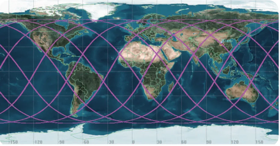
For a spacecraft, the HSS must move in orbit. Also through the choice of the orbit, a serious climate area can be targeted for key protection. Therefore, the orbital selection is designed and analyzed first. In the face of numerous orbits, the choice should consider three points. First, it is as much as possible to cover the solar radiation. Second, it is as much as possible to cover the land area, so that human comfort improved. Thirdly, it is as far as possible to make the shielding time fixed and regular, easy to carry out other assessments and observations. Because of all these factors, the synchronous orbit is more suitable than the others. It has the advantage of fixed orientation between the Sun-synchronous orbit plane and the Sun to ensure that the shielding surface over one location is at the same time every day. The orbital parameters can be determined by the latitude and longitude of the predetermined area on Earth. In this paper, the predetermined area is Xi’an, as an example.
The Xi’an region is at lat 34o 16’ N and long 108o 56’ E, which is located in China’s inland plains, which is the warm
temperate semi-humid continental monsoon climate. The area has four distinct seasons. With the intensification of the greenhouse effect, the mean annual average temperature in the region shows a significant upward trend, which is higher than the change rate of other parts in China (Xiaoling et al. 2011). According to the above area selection, the orbit parameters would be determined. The design of a large eccentricity solar-synchronous orbit is referred to (Bo et al. 2008). Based on the formulas from that and considering the characteristics of the HSS, this paper makes an analysis of the method for the determination of the orbit and the six parameters of the orbit are mainly to be designed.
C−4p+𝑅𝑅! !𝑎𝑎!!+4 p+𝑅𝑅! !𝑎𝑎!!− p+𝑅𝑅! !𝑎𝑎!!!=0
4𝑛𝑛𝑛𝑛 p+𝑅𝑅! !𝑎𝑎!!−4𝑛𝑛𝑛𝑛 p+𝑅𝑅! !𝑎𝑎! !+ 𝑛𝑛𝑛𝑛−4𝑚𝑚 p+𝑅𝑅! ! +𝑛𝑛𝑛𝑛 p+
𝑅𝑅! !𝑎𝑎! !+4𝑚𝑚 p+𝑅𝑅! !𝑎𝑎−𝑚𝑚 p+𝑅𝑅! !=0
𝑅𝑅! i a ω p
C f t
• Semi-‐major axis: 10560.27 km
• Eccentricity: 0.35
• Inclination: 116.57°
• Right ascension: 101.308°
C−4 p+𝑅𝑅! !𝑎𝑎! !+4p+𝑅𝑅! !𝑎𝑎!!− p+𝑅𝑅! !𝑎𝑎!!!=0
4𝑛𝑛𝑛𝑛 p+𝑅𝑅! !𝑎𝑎!!−4𝑛𝑛𝑛𝑛 p+𝑅𝑅! !𝑎𝑎!!+ 𝑛𝑛𝑛𝑛−4𝑚𝑚 p+𝑅𝑅! ! +𝑛𝑛𝑛𝑛 p+
𝑅𝑅! !𝑎𝑎!!+4𝑚𝑚p+𝑅𝑅! !𝑎𝑎−𝑚𝑚 p+𝑅𝑅! !=0
𝑅𝑅! ia ω p
C f t
• Semi-‐major axis: 10560.27 km
• Eccentricity: 0.35
• Inclination: 116.57°
• Right ascension: 101.308°
C−4p+𝑅𝑅! !𝑎𝑎!!+4 p+𝑅𝑅! !𝑎𝑎!!− p+𝑅𝑅! !𝑎𝑎!!!=0
4𝑛𝑛𝑛𝑛 p+𝑅𝑅! !𝑎𝑎!!−4𝑛𝑛𝑛𝑛 p+𝑅𝑅! !𝑎𝑎!!+ 𝑛𝑛𝑛𝑛−4𝑚𝑚 p+𝑅𝑅! ! +𝑛𝑛𝑛𝑛 p+
𝑅𝑅! !𝑎𝑎! !+4𝑚𝑚 p+𝑅𝑅! !𝑎𝑎−𝑚𝑚 p+𝑅𝑅! !=0
𝑅𝑅! i ω p
C f t
• Semi-‐major axis: 10560.27 km
• Eccentricity: 0.35
• Inclination: 116.57°
• Right ascension: 101.308°
(2) (1)
where REstands for the equatorial radius. The parameters i, α, ω and p denote the orbital inclination, semi-major axis, angular
velocity of the Earth’s revolution and perigee respectively. C, f and t means coefficients, the value of which could be obtained through the known parameters.
Given (m, n) for nonlinear equations the unknown semi-major axis and argument of perigee could be calculated from Eqs. 1 and 2. Considering the actual situation of the climate of Xi’an, m is equal to 1 and n is equal to 8. It means that the space vehicle
would move exactly eight circles in one day. According to the target area, the orbit is selected as follows:
• Semi-major axis: 10560.27 km
• Eccentricity: 0.35
• Inclination: 116.57°
• Right ascension: 101.308°
• Argument of perigee: 219.0055812°
• True anomaly: 180°
By using simulation software of ADAMS (Automatic Dynamic Analysis of Mechanical Systems), the ascending node is determined, as shown in Fig. 1. The orbit could be maintained by tracking control in actual launch. It could ensure that the space vehicle moves the target area at the same time every day and as much as possible over land.
C−4 p+𝑅𝑅! !𝑎𝑎!!+4 p+𝑅𝑅! !𝑎𝑎!!− p+𝑅𝑅! !𝑎𝑎!!!=0
4𝑛𝑛𝑛𝑛 p+𝑅𝑅! !𝑎𝑎! !−4𝑛𝑛𝑛𝑛 p+𝑅𝑅! !𝑎𝑎! !+ 𝑛𝑛𝑛𝑛−4𝑚𝑚 p+𝑅𝑅! ! +𝑛𝑛𝑛𝑛 p+
𝑅𝑅! !𝑎𝑎!!+4𝑚𝑚 p+𝑅𝑅! !𝑎𝑎−𝑚𝑚p+𝑅𝑅! !=0
𝑅𝑅! i a ω p
C f t
• Semi-‐major axis: 10560.27 km
• Eccentricity: 0.35
J. Aerosp. Technol. Manag., São José dos Campos, v10, e0918, 2018
DEPLOYING ABILITY ANALYSIS
The HSS is launched by a carry rocket into space orbit. At load, the system is folded. Therefore, it is important that the process is comfortable from the fold to the deployment. Only expand the system to be useful.
The HSS in orbit consists of three parts, which are large shielding surface, cables and control mechanism. The deployment of the system is divided into two steps. The first step is the expansion of the cables connected with the shielding surface and the control mechanism. Because of the existence of gravity difference, the two objects that are connected by tethers could be self-expanding and self-balancing in space. Therefore, this step is easy to succeed. The second step is the deployment of the shielding surface, which are the working part of the HSS. The system would be always in working state and does not need to be folded after deploying. Therefore, this paper mainly studies the deployment of shielding surface.
The solar radiation could be shielded by shielding surface. The larger the diameter the more solar radiation would be shielded. If the surface is large enough, it could even cover the entire solar radiation for the Earth, the same as the total solar eclipse. However, taking into account the existing carrier rocket capacity and manufacturing processes, the area of the surface could not be infinite. The Long March 5 is the largest existing heavy rocket, which has a maximum capacity of 14 tons with elliptical orbit (CZ-5… 2016), thus the carrying capacity of 14 tons is a constraint condition of the design of HSS. In addition, when the diameter of shielding surface is 1.4 km, the total mass of HSS is close to 13.5 tons. Therefore, the diameter of the shielding surface is set as 1.4 km. The shape of a shielding surface is shown in Fig. 2. The backbone is a folded hoop labeled A. Surface mesh with flexible filament labeled B constructs the surface with a thin reflective membrane labeled C on them. The outer diameter of A is 0.03 m and the thickness is 1 mm, with material properties of carbon fiber. The diameter of B is 0.3 mm and the surface density of C is 4.29 g/m2.
The total mass of the shielding surface is 8099.35317 kg, which could be carried by the Long March 5 Series Launch Vehicle.
Figure 1. HSS subastral point.
Figure 2. Shielding surface.
A
B
During the dynamic simulation, because of the large surface and numerous components, the simulation requires a lot of memory and time. The accuracy and results may not be ideal. The greatest impact on the simulation is the flexible filament and reflective membrane, because they are heavy and widely distributed. In the simulation, this part is divided into an enormous number of units, which directly affect the simulation results and speed. Therefore, it is necessary to simplify the model, mainly to simplify the filament and membrane. In this paper, two kinds of simplified methods are used. First, the filament and membrane are completely simplified. Second, the filament and membrane are semi-simplified.
COMPLETELY SIMPLIFIED FOR DEPLOYING
The method of completely simplified is to ignore the entity state of the flexible filament and reflective membrane, and their quality is divided into each folded hoop. The model is established to research the shielding surface with development case. This method is the most direct and simple way, but its precision is the lowest. Since a wide range of entities is simplified, the motion equation is reduced. Then, the speed of operation is improved and the accuracy is also reduced.
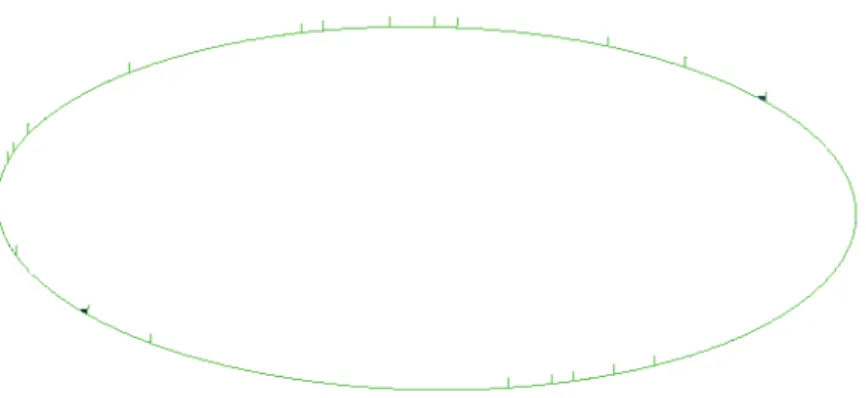
In this instance, a shielding surface dynamic model with a diameter of 1.4 km was constructed (assuming zero gravity), with the hoop of the structure divided into 240 sections, each with a fixed truss composed of rods. Each rod is a thin-walled round tube, the outer diameter of the cross section is 0.030 m, and the thickness is 0.0005 m, which could meet launch size of the Long March 5 Series Launch Vehicle. The material of the rigid rod is assumed to be carbon fiber and the joints on the hoop are assumed to be aluminum. The stowed size of the rigid structure has 5 m diameter and 18.3254 m high. Figure 3 illustrates the antenna backbone in stowed (i.e., folded) configuration, and Fig. 4 shows the backbone in deployed configuration.
Figure 4. Deployed backbone of the dynamic model by completely simplified. Figure 3. Stowed backbone of the dynamic model by completely simplified.
J. Aerosp. Technol. Manag., São José dos Campos, v10, e0918, 2018
dynamic simulation software. It can be clearly seen that the shielding surface is a ring composed of a number of hoop after the development. The rest of the entity is ignored.
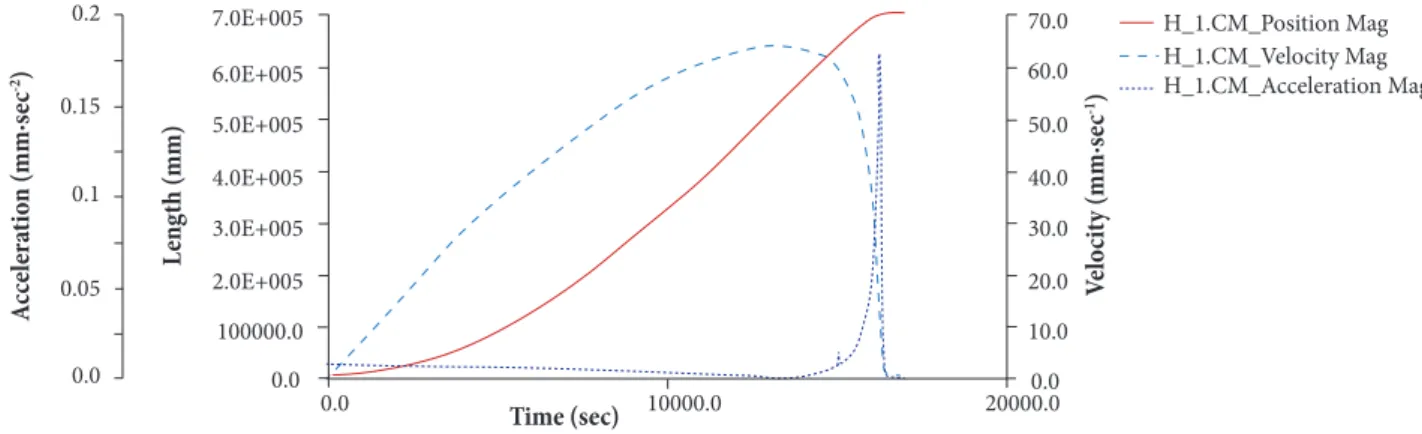
The deploying process curves of a representative joint H_1 on the hoop are shown in Fig. 5, where the deployment process of a folded hoop H_1 is tracked throughout the deployment. From these curves, we can see that the H_1 folded hoop reaches the expected position with the velocity and acceleration gradually tapering zero, consistent with what would be required for a successful deployment. While this example is idealized and symmetrical compared to an actual deployment on orbit, it is simple to analyze and relatively easy to test on the ground.
Figure 5. Deploying process curves of H_1 by completely simplified.
Figure 6. Diameter of deploying by completely simplified.
A cc ele ra tio n (mm· se c -2) V elo ci ty (mm· se c -1) Time (sec) L en gth (mm) H_1.CM_Position Mag H_1.CM_Velocity Mag H_1.CM_Acceleration Mag 7.0E+005 6.0E+005 5.0E+005 4.0E+005 3.0E+005 2.0E+005 100000.0 0.0
0.0 10000.0 20000.0
0.2 0.15 0.1 0.05 0.0 70.0 60.0 50.0 40.0 30.0 20.0 10.0 0.0 Time (sec) L en gth (mm) 20000.0 1.5E+006 1.0E+006 5.0E+005 0.0
0.0 5000.0 10000.0 15000.0
MEA_PT2PT_1441
The simulation time to be 17000 seconds with 1142 steps, the model could be deployed successfully as shown in Fig. 6. The final diameter of the model is 1.4 km.
SEMI-SIMPLIFIED FOR DEPLOYING
The method of semi-simplified means that the flexible filament and reflective membrane are considered as soft ribs, which are distributed in the radius line of shielding surface. The more the number of soft ribs, the more similar to the actual morphology of shielding surface. This method not only avoids the total neglect, but also cut down the number of entities. As long as the number of soft ribs is appropriate, it could get suitable results both saving time and effective simulation.
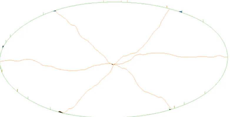
of the torsion springs of each joint in the hoop, the structure was shown to deploy successfully. The deployed structure is shown in Fig. 8. For comparison, the rest of this model is the same as the above method.
Figure 8. Deployed backbone of the dynamic model by semi-simplified. Figure 7. Stowed backbone of the dynamic model by semi-simplified.
The deploying process curves of a folded hoop H_1 are shown in Fig. 9. These curves show that the H_1 folded hoop reaches its desired position with velocity and acceleration gradually tapering to zero.
The simulation time to be 1040000 seconds with 1142 steps, the model can be deployed successfully as shown in Fig. 10. The final diameter of the model is about 1.4 km.
Both of these two models show that the shielding surface can be deployed to a predetermined size. The first method is simpler than the second method, so the same number of steps in the first simulation process costs less time. However, the precision of the
Figure 9. Deploying process curves of H_1 by semi-simplified.
A
cc
ele
ra
tio
n (mm·
se
c
-2)
V
elo
ci
ty (mm·
se
c
-1)
Time (sec)
L
en
gth (mm)
H_1.CM_Position Mag H_1.CM_Velocity Mag H_1.CM_Acceleration Mag 7.5E+005
6.0E+005
4.5E+005
3.0E+005
1.5E+005 0.1
0.0
0.0 5.0E+005 1.0E+006 1.5E+006
0.25
0.2
0.15
0.05
0.0
45.0
35.0
25.0
15.0
5.0 40.0
30.0
20.0
10.0
J. Aerosp. Technol. Manag., São José dos Campos, v10, e0918, 2018
Figure 10. Diameter of deploying by semi-simplified.
MEA_PT2PT_1441_2
L
en
gth (mm)
1.5E+006
1.0E+006
5.0E+005
0.0
Time (sec)
0.0 5.0E+005 1.0E+006 1.5E+006
second method is obviously higher than that of the first method, and it is more convincing. With the number of soft rib increasing, its accuracy would infinitely close to the real situation. At the same time, the simulation time would be took by several times. In summary, it recommends that the semi-simplified and the reasonable number of the soft rib is better. The simulation results show that the shielding surface is feasible.
FORCE ANALYSIS
After the HSS has been deployed to the working state, it is also critical to maintain this state. Only continuous shielding could produce satisfactory results. For the HSS the pull and deformation of the cables are related to the maintenance of the deployment state. If the deformation would be beyond the elastic elongation of the cables, the cables would be fractured, and then the whole system would fail. At the same time, although the surface precision requirements are not as high as the antenna, it is still hoped that the basic shape of the shielding surface does not change after the force acted on. Otherwise, it would be unable to achieve the desired effect.
To predict the deformation of the tethers and shielding surface, two static analyses are carried out. The first one mainly analyzes the tethers deformation. A simplified Finite Element Methods (FEM) model of the HSS has 1.4 km diameter was constructed and analyzed. The hoop is divided into 240 sections, each with a fixed truss. The fixed truss rods on the hoop are all thin-walled round carbon fiber tubes, the outer diameter of the cross section is 0.030 m, and the thickness is 0.0005 m. All the flexible cables have a diameter of 0.003 m, with material properties of Kevlar. The film is modeled as countless small shell, the thickness is 0.75e-5m, and the surface density is 0.00429 kg/m2. Three tethers are Kevlar with a diameter of
1 mm, and the length is 30 km. In theory, the tethers are connected with the shielding surface and the control mechanism. But in modeling, one end of the tethers is respectively connected to the three points at the circumference of the shielding surface, and the other end is fixed at the three equal points of diameter 5 m circumference outside 30 kilometers (5 m is the diameter of the control mechanism). These structural parameters were selected close to be consistent with the above mentioned dynamic analysis models.
Through this static analysis, assuming zero gravity, and through further analysis and optimization, the system was finally balanced with a maximum displacement of 60.12 m, as shown in Fig. 11. This length is within the allowable elongation of the 30 km Kevlar.
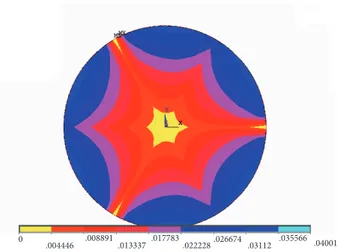
The second one mainly analyzes the deformation of the shielding surface. Therefore, based on the first model, the tethers are removed. The tethers’ force is directly applied to the shielding surface. Through this static analysis, assuming zero gravity, it can be seen that the basic shape of shield surface is still maintained after the force acted on. The result is shown in Fig. 12.
CONCLUSION
For mitigating global warming, we discuss HSS, a spacecraft used to reduce solar radiation from the Sun to the Earth. Because the system is located in space, it does not destroy the atmospheric structure and will not cause other secondary climate problems. However, as the HSS is restricted by the diameter of the shielding surface, a small part of solar radiation could be blocked. But even the global mean surface temperature will also go down and the global warming will be alleviated, by this way. It is like an umbrella to protect the Earth.
Most importantly, the HSS has some superiority that is compared with other scenarios. The advantage of the HSS is obvious, such as low-cost, non-space assembly and few launches. Each coin has both sides. The HSS has also some weaknesses: the area of shielding surface is large; the assembly on ground is complex and time-consuming. In addition, the weight of the thin reflective membrane need to be light as we can, but it could not influence the effect of blocking the solar radiation. So the material is relatively rare currently. As time is passing, these problems could be overcome with the improvement of manufacturing level. On the whole, the HSS has also great value.
Figure 11. Analysis result of the HSS.
Figure 12. Analysis result of the shield surface. 0
6.68 13.36
20.04 33.4 40.08 46.76 53.44
60.12 26.72
0
.004446 .008891
.013337 .022228.026674 .03112
J. Aerosp. Technol. Manag., São José dos Campos, v10, e0918, 2018
In this paper, all the analyses revolve around the orbit, the orbit selection, the deployment at entering orbit and the stability in orbit performing. From the analysis, results can be seen that the HSS with the existing carrier rocket could be deployed smoothly and run stably after reaching the Sun synchronous orbit. Therefore, using HSS to mitigate global warming is feasible in the future. However, the structure and the shielding efficiency in this article have not been mentioned, this is the focus on the direction of future research. May this technology be applied as soon as possible to change our lives.
AUTHOR’S CONTRIBUTION
Both authors contributed equally.
REFERENCES
Angel R (2006) Feasibility of cooling the Earth with a cloud of small spacecraft near the inner Lagrange point (L1). Proceedings of the National Academy of Sciences of the United States of America 103(46):17184-9. doi: 10.1073/pnas.0608163103
Bershadskii A (2009) Transitional solar dynamics and global warming. Physica A-Statistical Mechanics and Its Applications 388(15-16):3213-3224. doi: 10.1016/j.physa.2009.04.020
Bo M, Chao H, Weijun H (2008) Optimization of special elliptic constellation for regional coverage. Journal of Beijing University of Aeronautics and Astronautics 34(2):165-170.
CZ-5 Vehicle Y-1 Rollout (2016) Space Launch Report [accessed 2017 Dec 01]. http://www.spacelaunchreport.com/index.html.
Guoqing Z, Pengfei L, Li H, Yaofei W (2008) Time series analysis and prediction of global average temperature over the next 50 years. Gansu Science and Technolog 24(17):72-74.
Hansen J, Sato M, Ruedy R, Lacis A, Oinas V (2000) Global warming in the twenty-first century: an alternative scenario. Proceedings of the National Academy of Science of the United States of America 97(18):9875-9880.
Hastings A, Clifton-Brown J, Wattenbach M, Stampfl P, Mitchell CP, Smith P (2008) Potential of Miscanthus grasses to provide energy and hence reduce greenhouse gas emission. Agronomy for Sustainable Development. 28(4):465-472. doi: 10.1051/agro:2008030
IPCC Working Group I (2013) The physical science basis [accessed 2017 Dec 01]. http://www.ipcc.ch/
Körner C, Basler D (2010) Phenology under global warming. Science 327(5972):1461-1462. doi: 10.1126/science.1186473
Mark HS, White DH, Mckeon GM, Scanlan JC, Carter JO (1994) Methods for exploring management options to reduce greenhouse gas emission from tropical grazing systems. Climatic Change. 27(1):49-70. doi: 10.1007/978-94-015-8328-2_6
Masiur RS, Khondaker AN (2012) Mitigation measures to reduce greenhouse gas emission and enhance carbon capture and storage in Saudi Arabia. Renewable and Sustainable Energy Reviews 16(5):2446-2460. doi:10.1016/j.rser.2011.12.003
NOAA. State of the Climate in 2015 [accessed 2017 Dec 01]. http://www.ncdc.noaa.gov/
Nordhaus WD, Mendelsohn R, Shaw D (1994) The impact of global warming on agriculture: A Ricardian analysis. American Economic Review 84(4):753-771.
Pickin JG, Yuen S, Hennings H (2002) Waste management options to reduce greenhouse gas emission from paper in Australia. Atmospheric Environment. 36(01):741-752. doi: 10.1016/s1352-2310(01)00532-5
Root TL, Price JT, Hall KR, Schneider SH (2003) Fingerprints of global warming on wild animals and plants. Nature 421(6918):57-60. doi: 10.1038/nature01333
Saxe H, Cannell MGR, Johnsen O, Ryan MG, Vourlitis G (2001) Tree and forest functioning in response to global warming. New Phytologist 149(3):369-399. doi: 10.1046/j.1469-8137.2001.00057.x
Sloan T, Wolfendale AW (2011) The contribution of cosmic rays to global warming. Journal of Atmospheric and Solar-Terrestrial Physics 73(16):2352-2355. doi: 10.1016/j.jastp.2011.07.013
Tirole J (2008) Some economics of global warming. Rivista di Politica Economica 98(6):9-42.
Usoskin IG, Schüssler M, Solanki SK, Mursula K (2005) Solar activity, cosmic rays, and Earth’s temperature: A millennium-scale comparison. Journal of Geophysical Research Atmospheres 110(A10). doi: 10.1029/2004ja010946
Vautard R, Gobiet A, Sobolowski S, Kjellström E, Stegehuis A, Watkiss P, Mendlik T, Landgren O, Nikulin G, Teichmann C, Jacob D (2014) The European climate under a 2 global warming. Environmental Research Letters 9(3):9-10.
Xiaoling L, Shuyan Y, Haiyan W (2011) Analysis on extreme temperature events during 1951-2009 in Xian. Journal of Arid Land Resources and Environment. 25(5):113-116.