obtained for all other uses, in any current or future media, including reprinting/republishing
this material for advertising or promotional purposes, creating new collective works, for resale
or redistribution to servers or lists, or reuse of any copyrighted component of this work in
other works.
L. M. R. Oliveira, and A. J. Marques Cardoso, "A permeance‐based transformer model and its
application to winding interturn arcing fault studies," IEEE Trans. Power Del, vol. 25, no. 3, pp.
1589‐1598, July 2010.
Corrected in: "Correction to “A Permeance‐Based Transformer Model and Its Application to
Winding Interturn Arcing Fault Studies” [Jul 10 1589‐1598]", IEEE Trans. Power Del, vol. 26, no.
1, pp. 486,
Jan. 2011
.
http://ieeexplore.ieee.org/xpl/articleDetails.jsp?tp=&arnumber=5406040&url=http%3A%2F%2
Fieeexplore.ieee.org%2Fiel5%2F61%2F5491350%2F05406040.pdf%3Farnumber%3D5406040
Abstract—This paper investigates the behavior of power
transformers under the occurrence of permanent or intermittent winding insulation faults. For the study of these phenomena, a simple and efficient permeance-based electromagnetic trans-former model is proposed, which is based on the simultaneous consideration of both magnetic and electric equivalent circuits. To incorporate the internal faults in this model a suitable equiva-lent circuit of the faulty winding is described. With the aid of this transformer model, the on-load exciting current Park's Vector Approach will be applied for diagnosing the occurrence of per-manent and intermittent winding faults. Experimental and simu-lation tests results are presented in the paper, which demonstrate not only the adequacy of the digital transformer model for wind-ing fault studies, but also the effectiveness of the proposed tech-nique for detecting winding inter-turn insulation faults in oper-ating three-phase transformers.
Index Terms—Transformers, transformer model, winding
in-sulation faults, winding fault diagnosis, Park's Vector Approach.
I. INTRODUCTION
ower and distribution transformers have formed an essen-tial part of electricity supply networks since the alternating current system was adopted more than a century ago [1]. Fail-ure of a power transformer may cause a break in power supply and loss of profits. Consequently, it is of great importance to detect incipient failures in power transformers as early as possible, so that they can be switched off safely and improve the reliability of power systems [2]. Therefore, it is quite ob-vious the need for the development of on-line diagnostic tech-niques that would aid in transformer maintenance. A survey of the most important methods, actually in use, for condition monitoring and diagnostics of power and distribution trans-formers, presented in [3], stresses the need for the develop-ment of new diagnostic techniques, which can be applied
Manuscript received … . This work was supported in part by the Portu-guese Foundation for Science and Technology (FCT) under Project Nº SFRH/PROTEC/49261/2008 and Project Nº SFRH/BSAB/950/2009.
L. M. R. Oliveira is with the High Institute of Engineering, University of Algarve, P-8005-139 Faro, Portugal and also with the Instituto de Telecomu-nicações, Coimbra P-3030-290, Portugal (e-mail: [email protected]).
A. J. M. Cardoso is with the Department of Electrical and Computer Engi-neering, Faculty of Sciences and Technology, University of Coimbra, P-3030-290 Coimbra, Portugal and also with the Instituto de Telecomuni-cações (e-mail: [email protected]).
Digital Object Identifier …
without taking transformers out of service, and which can also provide a fault severity criteria, in particular for determining transformer winding insulation faults.
The most difficult transformer winding fault for which to provide protection is the fault that initially involves only one turn [4]. Initially, the insulation breakdown leads to internal arcing, which results in a low current, high impedance fault [5]. Usually, this incipient inter-turn insulation failure does not draw sufficient current from the line to operate an ordinary overload circuit-breaker or even more sensitive balanced pro-tective gear [6]. This turn-to-turn fault will then progress, with random propagation speed, involving additional turns and lay-ers, leading to a high current, low impedance fault, [7], [8]. The transformer will, in fact, be disconnected from the line automatically when the fault has extended to such degree as to embrace a considerable portion of the affected winding [6].
As stated above, the initial turn-to-turn insulation defect leads to an arcing fault that may have a low current magni-tude. Arcing faults usually cause damage that is limited to the fault area, and pose a great danger to the transformer [9]. When the voltage potential between the affected turns breaks down the insulation a spark discharge takes place. The arc ig-nition and extinction depends on this threshold voltage [10], [11], resulting in a fault of intermittent nature. The behavior of the transformer winding currents under the occurrence of this type of fault should be clearly understood, in order to allow the detection of the failure in its incipient stage.
Previous research, concerning the use of the Park's Vector Approach, has demonstrated the effectiveness of this non-invasive technique for diagnosing malfunctions in oper-ating three-phase induction motors, power electronics and ad-justable speed drives [12]. Preliminary experimental results, presented in [3], concerning the use of the supply current Park's Vector Approach, have also demonstrated the effective-ness of this technique for diagnosing the occurrence of inter- -turn insulation faults in the windings of operating three-phase transformers. The on-line diagnosis is based on identifying the appearance of an elliptic pattern, corresponding to the trans-former supply current Park's Vector representation, whose el-lipticity increases with the severity of the fault and whose ma-jor axis orientation is associated with the faulty phase. How-ever, with this approach, it is difficult to discriminate between unbalanced loads and winding faults. To overcome this diffi-culty, an improved diagnostic technique was implemented,
A Permeance-Based Transformer Model and its
Application to Winding Inter-Turn
Arcing Fault Studies
Luís. M. R. Oliveira and A. J. Marques Cardoso, Senior Member, IEEE
which consists of the analysis of the so-called on-load exciting current Park's Vector pattern, and, therefore unaffected by the transformer's load conditions [13].
The experimental study of winding inter-turn short-circuits occurrence presents some difficulties, mainly due to the high magnitudes of the faulty currents involved, which can damage the test transformer. Therefore, a detailed analysis of these phenomena can be better investigated by the use of a suitable digital simulation transformer model. For that purpose, a cou-pled electromagnetic transformer model was developed [14], which is based on the combination of both magnetic and elec-tric lumped-parameters equivalent circuits. The concept of duality is not used and the magnetic circuit of the transformer is not converted into analogous electrical equivalents. This al-lows the transformer to be defined and simulated in its natural electromagnetic environment so that cause-and-effect relation-ships can be closely investigated [15].
With the aid of this transformer model, the on-load exciting current Park's Vector Approach will be applied for diagnosing the occurrence of permanent and intermittent winding insula-tion faults, which is the scope of this paper.
II. DIGITAL SIMULATION OF WINDING INTER-TURN
SHORT-CIRCUITS
A. Transformer model for normal operating conditions
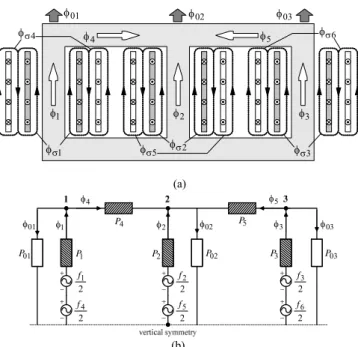
The coupled electromagnetic transformer model consists in the combination of both magnetic and electrical equivalent circuits, in order to obtain the flux-current relationships. A typical flux distribution for a three-phase, three-limb, two winding, core-type transformer is sketched in Fig. 1(a). Tak-ing advantage of the vertical symmetry of the transformer, the magnetic equivalent circuit can be derived, as shown in Fig. 1(b), consisting of magnetomotive forces (MMF), fi, and
lumped (linear and non-linear) permeances, Pi. As a first
ap-proach, let's consider only the excited windings and neglect the leakage fluxes associated with each winding. In a similar manner to that presented in [15]-[17], the flux-MMF non-linear relation (–f) can be expressed as:
1 11 12 13 1 2 21 22 23 2 3 31 32 33 3 i i a a a f a a a f a a a f A f (1) where:
2
1 11 2 1 1 1 22 33 23 a P P P P P D (2) 1 12 21 2 1 2 12 33 a a P P P P D (3) 1 13 31 2 1 3 12 23 a a P P P P D (4)
1 22 2 2 1 2 11 33 a P P P P D (5) 1 23 32 2 2 3 11 23 a a P P P P D (6)
2
1 33 2 3 1 3 11 22 12 a P P P P P D (7) 2 12 33 2 23 11 33 22 11 P P P P P P P D A (8) and: 01 4 1 11 P P P P (9) 4 12 P P (10) 02 5 4 2 22 P P P P P (11) 5 23 P P (12) 03 5 3 33 P P P P (13)Recognizing that f N1i and N1, the main linkage
fluxes, which do not take into account the leakage fluxes, can be expressed, from (1), as:
i A λ 2 1 N h (14)
The total linkage fluxes can now be computed, introducing the leakage fluxes, as follows:
t h
λ λ L i L i (15)
being L the diagonal leakage inductance matrix. It is assumed
that there is an individual leakage inductance associated with each winding, which is determined from the conventional short-circuit test, where the per-unit primary and secondary leakage inductances are equal.
When the transformer's secondary-side is loaded, there are two MMF's in each limb. It is now necessary to expand (1), as follows: 1 11 12 13 1 1 2 4 2 21 22 23 1 2 2 5 3 31 32 33 1 3 2 6 a a a N i N i a a a N i N i a a a N i N i (16)
which leads to a system of six equations: t λ Γ i (17) where: 1 2 1 1 2 1 2 1 2 2 N N N N N N σ A A Γ L L A A (18) and: diagLp Lp Lp Ls Ls Ls σ L (19)
being Lp and Ls the primary and secondary winding leakage
inductances, respectively.
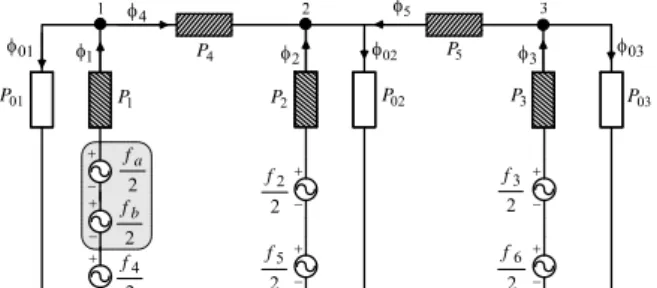
The winding connections are established, in the model, from the equivalent electric circuit, which is shown in Fig. 2 for the case of a wye-wye connection, with earthed neutrals and a phase shift of zero degrees (vector group YNyn0), and a balanced resistive load. The equations that describe the ter-minal conditions at each winding can be expressed as:
t
01 02 4 5 03 1 4 2 5 6 3 2 1 3 (a) 3 2 1 4 5 01 02 03 01 P P1 4 P 2 P 5 P 2 1 f 2 2 f 02 P P3 P03 2 3 f 2 4 f 2 5 f 2 6 f (b)
Fig. 1. (a) Flux distribution in a three-phase, three-limb, two-winding, core-type transformer, assuming a slightly greater magnetomotive force in the inner windings. (b) Equivalent magnetic circuit.
n R S T 1 i 2 i 3 i N 4 i n 5 i 6 i 2 3 1 5 6 4 3 L R 1 L R 2 L R
Fig. 2. Simplified equivalent electric circuit for the case of an YNyn0 con-nection and a balanced resistive load.
where:
T t t t t t t t 1 2 3 4 5 6 λ (21)
v1N v2N v3N 0 0 0
T v (22)
i i i i i i
T 6 5 4 3 2 1 i (23) ( 1) ( 2) ( 3) diag R R R R R R R R R p p p s L s L s L R (24)being Rp and Rs the primary and secondary winding
resis-tances, respectively.
In order to maintain a trade off between complexity and ac-curacy, an approximation was made to include the excitation losses, by connecting three non-linear resistance branches across the terminals of the excited windings.
The influence of the no-load losses conductances, Gfe, can
now be introduced in (17): v G λ Γ i t fe (25)
being Gfe a 66 matrix, where only the first 33 diagonal
sub-matrix has non-zero values.
The electromagnetic coupled transformer model is thus based on the combination of (20) and (25), which takes into account the asymmetry and saturation effects of the core.
B. Modeling winding inter-turn short-circuit faults
If the fault occurs in the primary winding, the short-circuited turns act as an autotransformer load on the winding, as shown in Figs. 3(a) and 3(b). However, if the fault takes place on the secondary winding, the short-circuited turns act as an ordinary double winding load, Fig. 3(c) [6].
To incorporate the internal faults in the aforementioned model, the faulty winding is divided into two parts: the healthy part (Na turns) and the faulty part (Nb turns), as shown
in Fig. 3(a), for the case of a fault in the primary winding (phase R), localized in the bottom part of the coil.
The resultant magnetic equivalent circuit is shown in Fig. 4, leading to three magnetomotive forces in the limb of the faulty phase. From the equivalent magnetic circuit, the –f re-lationship becomes: 1 11 12 13 1 2 4 2 12 22 23 1 2 2 5 3 13 23 33 1 3 2 6 a b b a a a N i N i N i a a a N i N i a a a N i N i (26)
The resultant main linkage fluxes are:
1 3 1 3 2 1 2 1 1 1 b hb h h h N N N N 3 2 6 2 2 5 1 2 4 N N N h h h (27)
from which the relation expressed by (17) can be computed, using:
T t t t tb t t t t 1 2 3 4 5 6 λ (28)
T b i i i i i i i1 2 3 4 5 6 i (29) 1 1 AA AB BA BB L L Γ L L L (30) and: b L a b N a N b N a N b N a a N b N a b N N p L a N a N a a N N a b N N a N p L a N a a N N b L a b N N a N a N a L a a N N 11 2 13 1 12 1 11 13 1 33 2 1 23 2 1 13 1 12 1 23 2 1 22 2 1 12 1 11 1 13 2 1 12 2 1 11 1 AA L (31) 13 2 12 2 11 2 33 2 1 23 2 1 13 2 1 23 2 1 22 2 1 12 2 1 13 2 1 12 2 1 11 2 1 a N b N a N b N a N b N a N N a N N a N N a N N a N N a N N a N N a N N a N N AB L (32) 13 2 33 1 2 23 1 2 13 2 12 2 23 1 2 22 1 2 12 2 11 2 13 1 2 12 1 2 11 2 a b N N a N N a N N a a N N a b N N a N N a N N a a N N a b N N a N N a N N a a N N BA L (33) s L a N a N a N a N s L a N a N a N a N s L a N 33 2 2 23 2 2 13 2 2 23 2 2 22 2 2 12 2 2 13 2 2 12 2 2 11 2 2 BB L (34)where La and Lb are the leakage inductances associated with
the subwindings a and b, respectively.
For the same type of fault, the corresponding electric equivalent circuit is shown in Fig. 5. The generic differential equation (20) still holds, but now with the fluxes vector of (28), the currents vector of (29) and:
v1N v2N v3N 0 0 0 0
T v (35) 0 0 0 0 0 0 0 0 0 0 0 0 0 0 0 0 0 0 0 0 0 0 0 0 0 0 1 0 0 0 0 0 0 0 2 0 0 0 0 0 0 0 3 Ra Rb R p R p Rsh Rsh Rb R RL R RL Rs RL s s R (36)where Ra and Rb are the resistances of the subwindings a and
b, respectively.
With this approach, the only additional data required for modeling winding inter-turn short-circuit faults, as compared to the healthy transformer model, are the leakage inductances and the resistances of the subwindings a and b.
Several short-circuit tests and analytical studies were con-ducted to determine La and Lb. It seems, however, that a
good approximation is obtained, for a generic k subwinding, 1 a N 1 i b i x i b N 1 N a b sh R 4 i 1 L R N2 c N 1 i 2 N 4 i b i x i 1 L R b N 1 N b 1 sh R c d d N 1N v 1N v a N 1 i 2 N 4 i b i x i 1 L R b N 1 N a b 1 sh R 1N v (a) (b) (c)
Fig. 3. Equivalent circuits for a fault localized in the (a) bottom part of the primary winding, (b) middle part of the primary winding and (c) bottom part of the secondary winding (phase R).
3 2 1 4 5 01 02 03 2 a f 2 2 f 2 3 f 2 4 f 2 5 f 2 6 f 2 b f 01 P P1 P2 P02 P3 P03 4 P P5
Fig. 4. Equivalent magnetic circuit for the case of a primary-side faulty winding (phase R). n 4 i n 5 i 6 i 2 i 3 i N a N Nb sh R 1 i R S T L3 R 1 L R 2 L R 5 6 4 2 3 1
Fig. 5. Equivalent electric circuit for the case of a primary-side faulty winding (phase R). by using: p k k L N N L 1 (37) Additionally, the leakage inductances do not change
sig-nificantly with the fault position along the affected winding. The subwindings resistances are also determined by a li-near relationship based on the corresponding turns ratio:
p k k R N N R 1 (38)
If the fault is localized in the upper part of the coil, the same methodology applies.
For a fault location in the middle part of the primary wind-ing, although two healthy subwindings (Nc and Nd turns) and
one faulty subwinding (Nb turns) have to be considered (Fig.
3(b)), the same methodology can also be applied, assuming
Na = Nc + Nd. With the approximations of (37) and (38), which
results in La = Lc + Ld and in Ra = Rc + Rd, respectively, the
relations (28) to (36) remain valid.
To model the occurrence of secondary-side winding faults, Fig. 3(c), a procedure similar to the one described above is al-so used.
For the simulation of intermittent defects a combination of both healthy and faulty models of the transformer is used. The model of the winding fault is only applied when the spark dis-charge takes place.
III. FAULT CHARACTERIZATION
For the experimental investigation a three-phase, two winding, three leg transformer, of 10.3 kVA, 230/132 V, was used. The primary and the secondary windings have 152 and 90 turns, respectively. In each winding of the transformer there are five additional tappings connected to the coils, al-lowing for the introduction of shorted turns at several loca-tions in the winding, as shown in Fig. 6, for the phase R of the transformer primary winding. In the results presented in this paper an YNyn0 transformer winding connection and a ba-lanced resistive load were used.
A. Permanent faults
The permanent faults are introduced in the test transformer connecting a shorting resistor at the terminals of the affected turns. The value of this resistor (Rsh) was chosen so as to
cre-ate an effect strong enough to be easily visualized, but simul-taneously big enough to limit the short-circuit current and thus protecting the test transformer from complete failure when the short is introduced. U UA UB UC UD UE U1 2 turns 2 turns 2 turns 2 turns 72 turns 72 turns
For the case of four permanent shorted turns in the phase R of the transformer primary winding and with Rsh = 0.39 Ω,
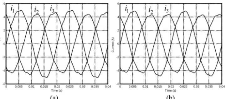
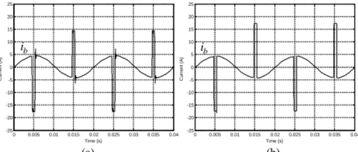
both experimental and simulated primary-side currents wave-forms are shown in Fig 7(a) and 7(b), respectively, which are in relatively good agreement (notation as per Fig. 3 and Fig. 5). The occurrence of primary-side inter-turn short-circuits leads to an increment in the magnitude of the current in the af-fected winding, as compared to a healthy condition, which re-sults in an unbalanced system of primary currents. In the pres-ence of the primary winding inter-turn short-circuits, the sec-ondary-side currents do not present any relevant change as compared to the transformer's healthy operation, remaining an approximately balanced three-phase system [14]. The current waveform in the shorted turns, ib, and the current waveform in
the fault impedance, ix, are shown in Fig. 8. The current ib is
approximately in phase opposition with i1, due to the
auto-transformer action of the shorted turns. The current in the short-circuit auxiliary resistor, ix, has a higher magnitude than
ib, since ix = i1– ib.
The input current in the affected winding can be divided in-to three terms:
1 4 e1 x
i i i (39) i
where i'4 is the secondary winding current referred to the
pri-mary-side, ie1 is the excitation current and i'x is the current in
the fault impedance, also referred to the primary-side. Obvi-ously, the two first terms are related with the healthy operation of the transformer while the last term arises due to the pres-ence of the shorted turns. The faulty current is reflected to the primary-side through the turns ratio between the number of shorted turns, Nb, and the total number of turns of the
primary-side winding, N1: 0 0.005 0.01 0.015 0.02 0.025 0.03 0.035 0.04 -6 -4 -2 0 2 4 6 Time (s) Curre n t ( A ) 1 i i2 i3 0 0.005 0.01 0.015 0.02 0.025 0.03 0.035 0.04 -6 -4 -2 0 2 4 6 Time (s) Curre n t ( A ) 1 i 2 i i3 (a) (b)
Fig. 7. Primary-side currents waveforms for the case of 4 permanent shorted
turns in the primary winding (phase R; Rsh = 0.39 Ω): (a) experimental; (b)
si-mulated. 0 0.005 0.01 0.015 0.02 0.025 0.03 0.035 0.04 -25 -20 -15 -10 -5 0 5 10 15 20 25 Time (s) Cu rr en t ( A ) b i x i 1 i 0 0.005 0.01 0.015 0.02 0.025 0.03 0.035 0.04 -25 -20 -15 -10 -5 0 5 10 15 20 25 Time (s) Cu rr en t ( A ) b i x i 1 i (a) (b)
Fig. 8. Fault related currents waveforms for the case of 4 permanent shorted
turns in the primary winding (phase R; Rsh = 0.39 Ω): (a) experimental; (b)
si-mulated.
1
x x b
i i N N (40)
As a result, the increase in the magnitude of the primary-side winding current, due to an incipient insulation defect, with on-ly a few turns involved, is small, even if the faulty current is large, and it is very likely that the fault remains undetected by the protection devices, until it progresses to a catastrophic failure. The severity of the fault depends not only on the num-ber of shorted turns, but also on the value of the fault current, which is limited by the fault impedance.
In the case of secondary-side winding faults, the additional load produced by the shorted turns also results into an incre-ment in the magnitude of the correspondent primary-side winding current, as compared to a healthy condition, as shown in Fig. 9. Again, the line currents of the secondary-side do not suffer any significant change with the introduction of the de-fect. However, with this type of fault, the current in the short-ed turns is in phase with the line current of the affectshort-ed winding, as shown in Fig. 10, and it takes larger values than the current in short-circuit auxiliary resistor.
The presence of the fault has the same end effect on the primary-side current, irrespective of whether the fault is lo-cated on the primary or on the secondary-side, and (39) and (40) remain valid for both conditions.
B. Intermittent faults
The arcing faults are introduced in the test transformer by connecting a custom built power electronics board, at the ter-minals of the affected turns. Basically, the power electronics circuit consists of two modules, each one with an Insulated Gate Bipolar Transistor (IGBT) in series with a power diode, connected in anti-parallel, as shown in Fig. 11(a). The arc
0 0.005 0.01 0.015 0.02 0.025 0.03 0.035 0.04 -6 -4 -2 0 2 4 6 Time (s) Cur ren t (A) 0 0.005 0.01 0.015 0.02 0.025 0.03 0.035 0.04 -6 -4 -2 0 2 4 6 Time (s) Cur ren t (A) 1 i i2 i3 i1 i2 i3 (a) (b)
Fig. 9. Primary-side currents waveforms for the case of 4 permanent shorted
turns in the secondary winding (phase R; Rsh = 0.31 Ω): (a) experimental; (b)
simulated. 0 0.005 0.01 0.015 0.02 0.025 0.03 0.035 0.04 -40 -30 -20 -10 0 10 20 30 40 Time (s) C u rren t (A ) 0 0.005 0.01 0.015 0.02 0.025 0.03 0.035 0.04 -40 -30 -20 -10 0 10 20 30 40 Time (s) C u rren t (A ) 4 i b i x i 4 i b i x i (a) (b)
Fig. 10. Fault related currents waveforms for the case of 4 permanent shorted
turns in the secondary winding (phase R; Rsh = 0.31 Ω): (a) experimental; (b)
ignition and extinction depends on the threshold voltage, which is regulated by the delay time and the conduction time (pulse width) of the IGBT's, Fig. 11(b). Again, an auxiliary shorting resistor was used, to maintain the fault current within safe values.
Fig. 12 presents the arc current waveform, ix, for the case
of four intermittent shorted turns in the phase R of the trans-former primary winding, maintaining the same load conditions and transformer winding connections mentioned above. In or-der to clearly visualize the transient phenomena, a pulse width of approximately 800 s was chosen.
As in the case of permanent faults, the arc current is re-flected to the primary-side through the turns ratio Nb/N1,
re-sulting in a pulse of relatively small magnitude in i1, as shown
in Fig. 13. Once again, the secondary-side currents do not pre-sent any significant change with the introduction of the defect.
The current waveform in the shorted turns is shown in Fig. 14. When ix is zero, the current in the defective turns is equal
to i1. During the arc discharge, ib presents a deep notch, since
ib = i1 – ix.
For the same aforementioned conditions, but now for the case of four intermittent shorted turns in the phase R of the transformer secondary winding, the current waveforms in the shorting resistor, in the primary and secondary-side windings of the affected phase and in the shorted turns are presented in Fig. 15, Fig. 16 and Fig. 17, respectively. In comparison with the previous test, the only significant difference is the current waveform in the shorted turns, which is now given by
ib = i4 – ix.
IV. WINDING FAULTS DETECTION BY THE ON-LOAD EXCITING
CURRENT PARK'S VECTOR APPROACH
The on-load exciting current waveforms are computed by adding the primary and secondary winding currents, both re-ferred to the primary-side. For the YNyn0 winding connection (Fig. 2) the on-load exciting currents are:
1 1 4 2 1 2 2 5 2 1 3 3 6 2 1 e e e i i i N N i i i N N i i i N N (41)
For the case of other transformer connections, the on-load exciting currents can be obtained by using the same basic principle, but with slightly different computations [13].
The transformer on-load exciting current Park's Vector components (ieD, ieQ) are:
2 3
1 1 6 2 1 6 3 eD e e e i i i i (42)
1 2 2 1 2 3 eQ e e i i i (43)Under ideal conditions, the three-phase on-load exciting currents lead to a Park's Vector with the following compo-nents:
6 2
ˆ sin
eD M i I (44) t Faulty windingIntermittent Fault Equivalent Circuit
sh
R
Delay time and pulse width adjustment 2 T 1 T x i Signal isolation and gate drive circuit Signal isolation and gate drive circuit in i b i Zero cross detection and pulse synchro-nization synchronization v Delay time Pulse width 1 GE T v 2 GE T v t t (a) (b)
Fig. 11. (a) Intermittent fault equivalent circuit with a power electronics board, (b) gate signals of the IGBT's.
0 0.005 0.01 0.015 0.02 0.025 0.03 0.035 0.04 -25 -20 -15 -10 -5 0 5 10 15 20 25 Time (s) C u rren t (A ) 0 0.005 0.01 0.015 0.02 0.025 0.03 0.035 0.04 -25 -20 -15 -10 -5 0 5 10 15 20 25 Time (s) C u rren t (A ) x i ix (a) (b)
Fig. 12. Arc current waveform for the case of a primary-side fault
(Rsh = 0.39 Ω): (a) experimental, (b) simulated.
0 0.005 0.01 0.015 0.02 0.025 0.03 0.035 0.04 -8 -6 -4 -2 0 2 4 6 8 Time (s) Cu rr e n t ( A ) 0 0.005 0.01 0.015 0.02 0.025 0.03 0.035 0.04 -8 -6 -4 -2 0 2 4 6 8 Time (s) Cu rr e n t ( A ) 1 i 4 i 1 i 4 i (a) (b)
Fig. 13. Primary and secondary-side currents waveforms of the affected phase
for the case of a primary-side fault (Rsh = 0.39 Ω): (a) experimental; (b)
simu-lated. 0 0.005 0.01 0.015 0.02 0.025 0.03 0.035 0.04 -25 -20 -15 -10 -5 0 5 10 15 20 25 Time (s) C u rren t (A ) 0 0.005 0.01 0.015 0.02 0.025 0.03 0.035 0.04 -25 -20 -15 -10 -5 0 5 10 15 20 25 Time (s) C u rren t (A ) b i ib (a) (b)
Fig. 14. Current waveform in the shorted turns for the case of a primary-side
fault (Rsh = 0.39 Ω): (a) experimental; (b) simulated.
6 2
ˆ sin
2
eQ M
i I t (45)
where ÎM is the maximum value of the on-load exciting current
(A), is the angular supply frequency (rad/s) and t is the time variable (s). The corresponding representation is a circular lo-cus centered at the origin of the coordinates. Under abnormal conditions (44) and (45) are no longer valid and consequently the observed picture differs from the reference pattern.
0 0.005 0.01 0.015 0.02 0.025 0.03 0.035 0.04 -30 -20 -10 0 10 20 30 Time (s) Curr ent ( A ) Curr ent ( A ) 0 0.005 0.01 0.015 0.02 0.025 0.03 0.035 0.04 -30 -20 -10 0 10 20 30 Time (s) x i ix (a) (b)
Fig. 15. Arc current waveform for the case of a secondary-side fault
(Rsh = 0.39 Ω): (a) experimental, (b) simulated.
0 0.005 0.01 0.015 0.02 0.025 0.03 0.035 0.04 -8 -6 -4 -2 0 2 4 6 8 Time (s) Curre n t ( A ) 0 0.005 0.01 0.015 0.02 0.025 0.03 0.035 0.04 -8 -6 -4 -2 0 2 4 6 8 Time (s) Curre n t ( A ) 1 i 4 i 1 i 4 i (a) (b)
Fig. 16. Primary and secondary-side currents waveforms of the affected phase
for the case of a secondary-side fault (Rsh = 0.39 Ω): (a) experimental; (b)
si-mulated. 0 0.005 0.01 0.015 0.02 0.025 0.03 0.035 0.04 -30 -20 -10 0 10 20 30 Time (s) C u rr en t (A ) 0 0.005 0.01 0.015 0.02 0.025 0.03 0.035 0.04 -30 -20 -10 0 10 20 30 Time (s) C u rr en t (A ) b i ib (a) (b)
Fig. 17. Current waveform in the shorted turns for the case of a secondary-
-side fault (Rsh = 0.39 Ω): (a) experimental; (b) simulated.
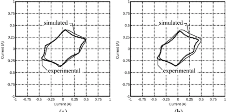
Fig. 18(a) presents the on-load exciting current Park's Vec-tor pattern for the case of an YNyn0 winding connection and for a healthy operation of the transformer. This pattern differs from the circular locus expected for an ideal situation, due to, among others, the non-linear behavior and asymmetry of the magnetic circuit. This is a well known phenomenon, which is revealed by the unbalanced and distorted nature of the ex-citing currents obtained from any three-phase no-load test. In fact, the exciting current Park's Vector pattern, obtained at no-load conditions, presents the same characteristics, as shown in Fig 18(b).
The occurrence of primary-side permanent winding faults manifests itself in the deformation of the on-load exciting cur-rent Park's Vector pattern corresponding to a healthy condi-tion, leading to an elliptic representacondi-tion, whose ellipticity in-creases with the severity of the fault and whose major axis ori-entation is associated to the faulty phase. This can be seen in Fig. 19, which presents the on-load exciting currents Park's Vector patterns, for different numbers of shorted turns in the primary windings, located in each one of the three phases.
For all the cases in Fig. 19, the auxiliary short-circuit re-sistor was adjusted in order to limit the magnitude of the
cur-rent in the shorted turns, Îb, to the rated magnitude of the
cur-rent in the affected winding, Î1n (Rsh = 0.31 Ω and
Rsh = 0.15 Ω for 4 and 2 shorted turns, respectively).
The simulated on-load exciting current Park's Vector pat-terns are presented in Fig. 20, which are in close agreement with the experimental results of Fig. 19.
Similar conclusions, concerning the on-load exciting cur-rent Park's Vector patterns, can be drawn for the occurrence of secondary-side inter-turn short-circuits.
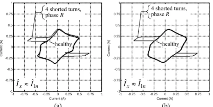
For the case of intermittent faults, the same operating phi-losophy is applied, but a spiked on-load exciting current Park's Vector pattern is obtained. As shown in Figs. 21, 22 and 23, the faulty phase is now detected by the pulsed pattern orientation. The evolution of the on-load exciting current Park's Vector pattern when the magnitude of the faulty current is increased can be observed in Figs. 24, 21 and 25 (where
Îx 0.5×Î1n, Îx Î1n and Îx 1.5×Î1n, respectively). The severity
of the fault is directly related with the magnitude of the pulsed pattern. Additionally, the results clearly indicate that the pro-posed diagnostic technique is sensitive to low level faults.
-1 -0.75 -0.5 -0.25 0 0.25 0.5 0.75 1 -1 -0.75 -0.5 -0.25 0 0.25 0.5 0.75 1 Current (A) Cu rr e n t ( A ) -1 -0.75 -0.5 -0.25 0 0.25 0.5 0.75 1 -1 -0.75 -0.5 -0.25 0 0.25 0.5 0.75 1 Current (A) Cu rr e n t ( A ) simulated experimental simulated experimental (a) (b)
Fig. 18. On-load exciting current Park's Vector pattern (a) and no-load excit-ing current Park's Vector pattern (b), for the case of an YNyn0 connection and healthy operating conditions.
-1 -0.75-0.5-0.25 0 0.25 0.5 0.75 1 -1 -0.75 -0.5 -0.25 0 0.25 0.5 0.75 1 Current (A) Cu rr en t ( A ) -1 -0.75-0.5-0.25 0 0.25 0.5 0.75 1 -1 -0.75 -0.5 -0.25 0 0.25 0.5 0.75 1 Current (A) Cu rr en t ( A ) 4 shorted turns 2 shorted turns healthy 1 ˆ ˆ b n I I -1 -0.75-0.5-0.25 0 0.25 0.5 0.75 1 -1 -0.75 -0.5 -0.25 0 0.25 0.5 0.75 1 Current (A) Cu rr en t ( A ) 4 shorted turns 2 shorted turns healthy 1 ˆ ˆ b n I I 4 shorted turns healthy 1 ˆ ˆ b n I I 2 shortedturns (a) (b) (c)
Fig. 19. Experimental on-load exciting current Park's Vector patterns for the cases of several percentages of permanent shorted turns in the primary wind-ings and for different faulty phases: (a) phase R; (b) phase S; (c) phase T.
-1 -0.75-0.5-0.25 0 0.25 0.5 0.75 1 -1 -0.75 -0.5 -0.25 0 0.25 0.5 0.75 1 Current (A) Cu rr en t ( A ) -1 -0.75-0.5-0.25 0 0.25 0.5 0.75 1 -1 -0.75 -0.5 -0.25 0 0.25 0.5 0.75 1 Current (A) Cu rr en t ( A ) -1 -0.75-0.5-0.25 0 0.25 0.5 0.75 1 -1 -0.75 -0.5 -0.25 0 0.25 0.5 0.75 1 Current (A) Cu rr en t ( A ) 4 shorted turns 2 shorted turns healthy 1 ˆ ˆ b n I I 4 shorted turns 2 shorted turns healthy 1 ˆ ˆ b n I I 4 shorted turns healthy 1 ˆ ˆ b n I I 2 shorted turns (a) (b) (c)
Fig. 20. Simulated on-load exciting current Park's Vector patterns for the cas-es of several percentagcas-es of permanent shorted turns in the primary windings and for different faulty phases: (a) phase R; (b) phase S; (c) phase T.
-1 -0.75 -0.5 -0.25 0 0.25 0.5 0.75 1 -1 -0.75 -0.5 -0.25 0 0.25 0.5 0.75 1 Current (A) C u rr ent ( A ) -1 -0.75 -0.5 -0.25 0 0.25 0.5 0.75 1 -1 -0.75 -0.5 -0.25 0 0.25 0.5 0.75 1 Current (A) C u rr ent ( A ) 4 shorted turns,
phase R 4 shorted turns,phase R
healthy healthy
1
ˆx ˆn
I I IˆxIˆ1n
(a) (b)
Fig. 21. On-load exciting current Park's Vector pattern for the case of four
intermittent shorted turns in the primary windings of phase R, with Îx ≈ Î1n
(Rsh = 0.39 Ω): (a) experimental; (b) simulated.
-1 -0.75 -0.5 -0.25 0 0.25 0.5 0.75 1 -1 -0.75 -0.5 -0.25 0 0.25 0.5 0.75 1 Current (A) Cu rr e n t ( A ) -1 -0.75 -0.5 -0.25 0 0.25 0.5 0.75 1 -1 -0.75 -0.5 -0.25 0 0.25 0.5 0.75 1 Current (A) Cu rr e n t ( A ) 1 ˆ ˆ x n I I IˆxIˆ1n healthy healthy 4 shorted turns,
phase S 4 shorted turns,phase S
(a) (b)
Fig. 22. On-load exciting current Park's Vector pattern for the case of four
intermittent shorted turns in the primary windings of phase S, with Îx ≈ Î1n
(Rsh = 0.39 Ω): (a) experimental; (b) simulated.
-1 -0.75 -0.5 -0.25 0 0.25 0.5 0.75 1 -1 -0.75 -0.5 -0.25 0 0.25 0.5 0.75 1 Current (A) Cu rr e n t ( A ) -1 -0.75 -0.5 -0.25 0 0.25 0.5 0.75 1 -1 -0.75 -0.5 -0.25 0 0.25 0.5 0.75 1 Current (A) Cu rr e n t ( A ) 1 ˆ ˆ x n I I IˆxIˆ1n 4 shorted turns, phase T healthy 4 shorted turns, phase T healthy (a) (b)
Fig. 23. On-load exciting current Park's Vector pattern for the case of four
intermittent shorted turns in the primary windings of phase T, with Îx ≈ Î1n
(Rsh = 0.39 Ω): (a) experimental; (b) simulated.
-1 -0.75 -0.5 -0.25 0 0.25 0.5 0.75 1 -1 -0.75 -0.5 -0.25 0 0.25 0.5 0.75 1 Current (A) C u rr ent ( A ) -1 -0.75 -0.5 -0.25 0 0.25 0.5 0.75 1 -1 -0.75 -0.5 -0.25 0 0.25 0.5 0.75 1 Current (A) C u rr ent ( A ) 1 4 shorted turns, phase , ˆx 0.5 ˆn R I I 1 4 shorted turns, phase , ˆx 0.5 ˆn R I I healthy healthy (a) (b)
Fig. 24. On-load exciting current Park's Vector pattern for the case of four
in-termittent shorted turns in the primary winding of phase R, with Îx ≈ 0.5 Î1n
(Rsh = 0.85 Ω): (a) experimental; (b) simulated.
-1 -0.75 -0.5 -0.25 0 0.25 0.5 0.75 1 -1 -0.75 -0.5 -0.25 0 0.25 0.5 0.75 1 Current (A) C u rr ent ( A ) -1 -0.75 -0.5 -0.25 0 0.25 0.5 0.75 1 -1 -0.75 -0.5 -0.25 0 0.25 0.5 0.75 1 Current (A) C u rr ent ( A ) 1 4 shorted turns, phase , ˆx 1.5 ˆn R I I healthy 1 4 shorted turns, phase , ˆx 1.5 ˆn R I I healthy (a) (b)
Fig. 25. On-load exciting current Park's Vector pattern for the case of four
in-termittent shorted turns in the primary winding of phase R, with Îx ≈ 1.5 Î1n
(Rsh = 0.31 Ω): (a) experimental; (b) simulated.
Other experimental and simulated tests carried out for dif-ferent types of the transformer windings connection, fault lo-cation and load conditions lead to similar conclusions to the ones presented before [13].
The diagnostic instrumentation system basically comprises a personal computer, a data acquisition board and clip-on cur-rent probes.
V. CONCLUSIONS
This paper describes the development and implementation of a permeance-based transformer model for the analysis of permanent and intermittent winding insulation faults. The model is based on the combination of both magnetic and elec-tric lumped-parameters equivalents circuits, which allows the modeling and simulation of the transformer in its natural elec-tromagnetic environment.
This paper also presents the application of the on-load ex-citing current Park's Vector Approach for diagnosing the oc-currence of intermittent inter-turn short-circuits in the wind-ings of operating three-phase transformers, which consists in the analysis of the on-load exciting current Park's Vector pat-terns. The on-line diagnosis of winding intermittent faults is based on identifying the appearance of a pulsed pattern, corre-sponding to the transformer on-load exciting current Park's Vector representation, whose pulse magnitude increases with the severity of the fault and whose major axis orientation is associated with the faulty phase. The proposed on-line diag-nostic technique combines the advantages of two well known methods:
the Park's Vector Approach, which assembles the three- -phase system in only one quantity;
the on-load exciting current, which enhances the severity of the fault, giving an increased sensitivity about the con-dition of the transformer.
Experimental and simulated test results were presented, for both permanent and intermittent winding insulation faults, which demonstrate the effectiveness of the diagnostic tech-nique.
REFERENCES
[1] C. Ashmore, "Transforming technology," International Power
Genera-tion, vol. 22, pp. 25-26, March 1999.
IEEE Trans. Power Delivery, vol. 18, pp. 164-169, Jan. 2003.
[3] A. J. M. Cardoso and L. M. R. Oliveira, "Condition monitoring and di-agnostics of power transformers," International Journal of COMADEM, vol. 2, pp. 5-11, July 1999.
[4] IEEE guide for protective relay applications to power transformers, IEEE Standard C37.91-2000, March 2000.
[5] P. Barkan, B. L. Damsky, L. F. Ettlinger, and E. J. Kotski, "Overpressure phenomena in distribution transformers with low impedance faults: ex-periment and theory," IEEE Trans. Power Apparatus and Systems, vol. 95, pp. 37-48, Jan./Feb. 1976.
[6] S. A. Stigant and A. C. Franklin, The J&P Transformer Book, 10th ed., London, Newnes-Butterworths, 1973.
[7] C. W. Plummer, G. L. Goedde, E. L. Petit, J. S. Godbee, and M. G. Hen-nessey, "Reduction in distribution transformer failures rates and nuis-ance outages using improved lightning protection concepts," IEEE
Trans. Power Delivery, vol. 10, pp. 768-777, Apr. 1995.
[8] J. M Lunsford and T. J. Tobin, "Detection of and protection for internal low-current winding faults in overhead distribution transformers", IEEE
Trans. Power Delivery, vol. 12, pp. 1241-1249, July 1997.
[9] N. Y. Abed and O. A. Mohammed, "Modeling and characterization of transformers internal faults using finite element and discrete wavelet transforms", IEEE Trans. on Magnetics, vol. 43, pp. 1425-1428, Apr. 2007.
[10] M. Gómez-Morante and D. W. Nicoletti, "A wavelet-based differential transformer protection", IEEE Trans. on PWRD, vol. 14, pp 1351-1359,
Oct. 1999.
[11] H. Wang, "Models for short circuit and incipient internal faults in single-phase distribution transformers," Ph.D. dissertation, Texas A&M Uni-versity, 2001.
[12] A. J. M. Cardoso, "The Park's Vector Approach: a general tool for diag-nostics of electrical machines, power electronics and adjustable speed drives," in Record of the 1997 IEEE Int.Symp. on Diagnostics for
Elec-trical Machines, Power Electronics and Drives, pp. 261-269.
[13] L. M. R. Oliveira, A. J. M. Cardoso and S. M. A. Cruz, "Transformers on-load exciting current Park's Vector Approach as a tool for winding faults diagnostics," in Conf. Record of the 15th Int. Conf. on Electrical
Machines (ICEM 2002), 6 pp, CD-ROM.
[14] L. M. R. Oliveira and A. J. M. Cardoso, "A coupled electromagnetic transformer model for the analysis of winding inter-turn short-circuits," in Record of the IEEE Int. Symp. on Diagnostics for Electrical
Ma-chines, Power Electronics and Drives, pp. 367-372, 2001.
[15] R. Yacamini, and H. Bronzeado, "Transformer inrush calculations using a coupled electromagnetic model," IEE Proc. Sci. Meas. Technol., vol. 141, pp. 491-498, Nov. 1994.
[16] M. Elleuch, and M. Poloujadoff, "A contribution to the modelling of three phase transformers using reluctances," IEEE Trans. on Magnetics, vol. 32, pp. 335-343, March 1996.
[17] X. S. Chen and P. Neudorfer, "Digital model for transient studies of a three-phase five-legged transformer" IEE Proc. Pt. C, vol. 139, pp. 351-359, July 1992.
Luís M. R. Oliveira was born in Coimbra,
Portu-gal in 1970. He received the Electrical Engineering Diploma and the M.Sc. degree from the University of Coimbra, Coimbra, Portugal, in 1995 and 2001, respectively, where he is currently pursuing the Dr. Eng. Degree in electrical engineering.
In 1996 he joined the High Institute of Engi-neering of Algarve University, Portugal, where he is currently an Adjunct Professor.
A. J. Marques Cardoso (S’89, A’95, SM’99) was
born in Coimbra, Portugal, in 1962. He received the E. E. diploma and the Dr. Eng. degree from the University of Coimbra, Coimbra, Portugal, in 1985 and 1995, respectively. Since 1985, he has been with the University of Coimbra, where he is currently an Associate Professor in the Depart-ment of Electrical and Computer Engineering and Director of the Electrical Machines Laboratory. His teaching interests cover electrical rotating ma-chines, transformers, and maintenance of electromechatronic systems and his research interests are focused on condition monitoring and diagnostics of elec-trical machines and drives. He is the author of a book entitled Fault Diagnosis in Three-Phase Induction Motors (Coimbra, Portugal: Coimbra Editora, 1991), (in Portuguese) and about 200 papers published in technical journals and con-ference proceedings.
Dr. Marques Cardoso is actively involved in the field of standardization on condition monitoring and diagnostics, both at the national and international level, where he has been acting as a convenor of ISO/TC 108/SC 5 Advisory Group C (Condition Monitoring of Electrical Motors and Generators, for the Purposes of Diagnostics), Advisory Group D (Condition Monitoring and Di-agnostics of Power Transformers) and Working Group 10 (Condition Moni-toring and Diagnostics of Electrical Equipment), and also a member of the IEEE Standards Association, and of several Working Groups and Balloting Committees of ISO, IEC and CEN.
He was a member of the Overseas Advisory Panel of Condition
Monitor-ing and Diagnostic Technology (a journal published by the British Institute of
Non-Destructive Testing between 1990-1993), and he is currently a member of the Editorial Board of the International Journal of Condition Monitoring &
Diagnostic Engineering Management, published by COMADEM
Interna-tional, UK, an Honorary Member of the International Biographical Centre Advisory Council, Cambridge, England, and also an Honorary Professor of the Albert Schwitzer International University, Geneva, Switzerland.
He has been acting as a member of the International Steering Committees and of the Technical Committees of several international conferences, Special
Sessions Organizer and Chairman of the 20th International Congress and
Ex-hibition on Condition Monitoring and Diagnostic Engineering Management, Faro, Portugal, June 13-15, 2007.
Dr. Marques Cardoso is a member of the New York Academy of Sciences, the European Power Electronics and Drives Association (EPE), the Interna-tional Association of Science and Technology for the Development, the Elec-trical Machines and the Industrial Drives Committees of the IEEE Industry Applications Society, the Electrical Machines and the Power Electronics Committees of the IEEE Industrial Electronics Society, the Technical Com-mittee on Diagnostics of the IEEE Power Electronics Society, the Portuguese Federation of Industrial Maintenance (APMI), and a senior member and Spe-cialist Engineer in Industrial Maintenance of the Portuguese Engineers Asso-ciation (ODE). He has been listed in Who's Who in the World, Who's Who in Science and Engineering, Who's Who in Finance and Industry, International Who's Who of Professionals and BEST Europe, among others.