Juri
Dezembro 2017
Francisco de Figueiredo e Silva Cunha Salvado
Licenciatura em Ciências Sociais Militares Master of Science in Naval Architecture
ESTUDO DO EFEITO SEQUENCIAL DE ONDAS DE
CHOQUE EM ESTRUTURAS CONFINADAS E
ADJACENTES
STUDY OF SEQUENTIAL EFFECTS OF
BLAST WAVES IN CONFINED AND ADJACENT
STRUCTURES
Dissertação para obtenção do Grau de Doutor em Engenharia Mecânica
Presidente: Doutor Jorge Joaquim Pamies Teixeira, Professor Catedrático, Faculdade de Ciências e Tecnologia, Universidade Nova de Lisboa Arguentes: Doutor Corneliu Cismasiu, Professor Associado,
Faculdade de Ciências e Tecnologia, Universidade Nova de Lisboa
Doutor Robert Ângelo Fontes Valente, Professor Associado, Universidade de Aveiro
Vogais: Doutor Victor José de Almeida e Sousa Lobo, Professor Catedrático, Centro de Investigação Naval, Escola Naval, Marinha
Doutor Filipe Miguel Horta e Vale Teixeira Dias, Senior Lecturer, School of Engineering, University of Edimburgh, UK
Orientador: Doutor Filipe Miguel Horta e Vale Teixeira Dias, Senior Lecturer, School of Engineering, University of Edimburgh Co-Orientador: Doutor João Mário Burguete Botelho Cardoso, Professor
Copyright
II
Copyright
Estudo do efeito sequencial de ondas de choque em estruturas confinadas e adjacentes
Copyright © 2017 Francisco de Figueiredo e Silva Cunha Salvado Faculdade Ciências e Tecnologia,
Universidade Nova de Lisboa
Acknowledgements
III
Acknowledgements
My gratitude:
- To my family and my father who regrettably left us too early.
- To Professors Filipe Teixeira Dias and João Burgete Cardoso for their diligent support, guidance and help.
- To Prof. Pamies Teixeira who opened to me the possibility to perform experimental work. His help was priceless.
- I also thank Prof. Victor Lobo who ensured the involvement and support from the Navy. A special thanks to the Submarine Squadron, in the person of its commanding officer Captain Silva Gouveia and to his team of instructors whose professionalism and expertise in the use and handling of explosives was much noticed and appreciated. To Sarg. Lourenço a special recognition for his support, encouragement and precious help.
- A very special reference to Mrs. Maria do Rosário Duarte from the Library and Documentation Division (Divisão de Documentação e Biblioteca) of FCT for her diligent help in the bibliographic research.
- I also thank Arsenal do Alfeite, SA for their support in the manufacturing of the test bench and aluminium alloy plate samples.
Resumo
V
Resumo
O estudo do efeito de ondas de choque explosivas em compartimentos fechados, em
particular as condições em que essas ondas se transmitem a compartimentos adjacentes e qual
o efeito produzido, afigura-se de grande interesse para a avaliação da vulnerabilidade de
edifícios, aeronaves e navios, sendo por isso um tema importante no âmbito da segurança e
defesa nacional, dada a natureza permanente e diversificada das ameaças do presente. Em
particular pretende-se, através da modelação numérica do fenómeno, estudar a resposta de dois
compartimentos adjacentes em que num deles ocorre uma explosão, procurando identificar o
efeito do volume e do material dos compartimentos nas condições em que se verifica a perda de
estanqueidade à onda de choque e o efeito da onda de choque sequencial na estrutura do
compartimento adjacente. Em conjunto com um estudo dos modos de colapso e de rotura de
materiais tipicamente utilizados na construção naval militar, neste caso a liga de alumínio
AA5083-H111, este trabalho constitui um contributo para uma ferramenta de projeto de navios
e embarcações militares, possibilitando análises e previsões da sua vulnerabilidade a diversos
tipos de explosivos e projéteis.
Palavras-Chave:
Onda de choque, Onda de choque explosiva, Explosão confinada, Ondas de choque confinadas,
Abstract
VII
Abstract
The study of the effect of explosive blast in confined spaces, particularly the conditions
under which blast is transmitted to adjacent compartments and the effects produced, is of
relevance for the vulnerability assessment of buildings, aircraft and ships, being of paramount
importance in the context of national security and defence due to the permanent and diverse
threats of present times. In particular it is aimed, through numerical modelling of the
phenomena, to study the response of adjacent compartments, one of them subjected to an
internal explosion, to identify the effect of compartment volume and material properties in the
conditions that will cause rupture and loss of structural integrity and the effect in neighbouring
structures of the sequential wave blast. Together with the study of the modes of collapse and
rupture of materials used in naval shipbuilding, in this case the AA5083-H111 aluminium alloy,
the present work will be the basis for the setting-up of a tool for the design of naval ships and
vessels, providing the means to analyse and predict their vulnerability to several types of
military ordnance.
Key-Words:
Table of Contents
IX
Table of Contents
Copyright... II
Acknowledgements ... III
Resumo ... V
Abstract ... VII
Table of Contents ...IX
List of Figures ... XV
List of Tables ... XXIII
Table of Acronyms ... XXV
1. Motivation, objectives and thesis organization ... - 1 -
1.1 Motivation ... - 1 -
1.2 Work methodology ... - 4 -
1.3Materials ... - 8 -
1.4 Organization of the thesis ... - 9 -
2. Explosives and blast waves... - 13 -
2.1 Nomenclature of explosives ... - 13 -
2.2 Explosives related phenomena ... - 19 -
2.3 The thermomechanics of explosions ... - 22 -
2.3.1 Introduction ... - 22 -
2.3.2 The physics of detonations ... - 33 -
2.3.3 Reflected waves ... - 36 -
2.4Scaling and other effects ... - 38 -
2.5Modelling detonation, empirical approach ... - 41 -
2.6Some empirical curves ... - 44 -
2.7The basic problem of a confined explosion ... - 50 -
Table of Contents
X
2.9Afterburn ... - 59 -
3. The effect of blast on structures ... - 63 -
3.1Introduction ... - 63 -
3.2Constitutive models – a review... - 65 -
3.2.1Framework of the review ... - 65 -
3.2.2Constitutive behaviour theory ... - 68 -
3.2.3Twinning ... - 73 -
3.2.4Dynamic recovery and recrystallization (DRV and DRX) ... - 74 -
3.2.5Constitutive equations ... - 77 -
3.2.6Physically based constitutive equations ... - 82 -
3.2.6.1Bodner and Partom (BP) ... - 84 -
3.2.6.2Steinberg-Guinan (SG) ... - 87 -
3.2.6.3Steinberg and Lund (SL) ... - 89 -
3.2.6.4Zerilli and Armstrong (ZA) ... - 90 -
3.2.6.5Mecking and Kocks (MK) ... - 93 -
3.2.6.6Mechanical Threshold Stress (MTS) ... - 94 -
3.2.6.7Nemat-Nasser and Li (NNL) ... - 97 -
3.2.7Other constitutive models ... - 99 -
3.2.8Critical analysis of the selected physically based models ...- 118 -
3.2.9Phenomenological constitutive equations ...- 122 -
3.2.9.1Molinari-Ravichandran (MR) ...- 123 -
3.2.9.2Johnson and Cook (JC) ...- 125 -
3.2.9.3Khan-Huang (KH) and Khan-Huang-Liang (KHL)...- 129 -
3.2.10Other phenomenological models ...- 134 -
3.2.11Comparison between the presented phenomenological models ...- 137 -
Table of Contents
XI
3.2.13Dynamic strength and fracture ...- 140 -
3.2.14Constitutive models – Some practical aspects ... …- 149 -
3.3Strength of plates subjected to blast loads ...- 150 -
3.4Aluminium alloy plates subject to blast loads...- 159 -
3.5Ductile fracture – Failure models ...- 164 -
3.6Damage model ...- 173 -
3.7Numerical difficulties and conclusions ...- 179 -
4. Numerical modeling ... - 181 -
4.1Introduction ...- 181 -
4.2Implicit and explicit integration ...- 184 -
4.3The Arbitrary Lagrangian Eulerian (ALE) approach ...- 188 -
4.3.1Lagrangian, Eulerian and ALE descriptions ...- 188 -
4.3.2Conservation laws in ALE description ...- 190 -
4.3.3The operator split ...- 192 -
4.3.4Advection and interface tracking algorithms ...- 195 -
4.3.5Artificial viscosity ...- 197 -
4.4Numerical modelling of a blast wave propagation ...- 198 -
4.5Consistent units ...- 199 -
4.6Equations of state ...- 199 -
4.6.1EOS for HE (*EOS_JWL card) ...- 200 -
4.6.2EOS for Air (*EOS_LINEAR_POLYNOMIAL card) ...- 203 -
4.7HE material definition (*MAT_HIGH_EXPLOSIVE_BURN card) ...- 205 -
4.7.1Burning model ...- 205 -
4.7.2 Properties of explosive materials ...- 206 -
4.7.3Properties of the Air (*MAT_NULL) ...- 208 -
4.8Hourglass ...- 209 -
Table of Contents
XII
4.9.1Lagrangian or MM-ALE approach ...- 210 -
4.9.2*CONSTRAINED LAGRANGE IN SOLID card ...- 213 -
4.10Johnson-Cook constitutive model ...- 215 -
5. The behaviour of blast waves in a confined space ... - 221 -
5.1Introduction ...- 221 -
5.2Confined explosions ...- 222 -
5.3Numerical model ...- 225 -
5.4Validation examples ...- 230 -
5.4.1Free air explosion – Validation example 1 ...- 231 -
5.4.2Confined explosion – Validation example 2 ...- 235 -
5.4.3Confined explosion – Validation example 3 ...- 236 -
5.5Parametric studies ...- 240 -
5.5.1Description of the simulations ...- 240 -
5.5.2Discussion of results - Data ...- 244 -
5.5.3Description of results – Qualitative description ...- 251 -
5.6Conclusions ...- 254 -
6. Blast loading of AA5083-H111 aluminium plates: Experimental and numerical analysis ... ………- 257
-6.1Introduction ...- 257 -
6.2Previous work on the strength of plates under blast loading ...- 258 -
6.3The strength of aluminium alloy plates subject to blast loads ...- 258 -
6.4Experimental set-up ...- 260 -
6.5Analysis of experimental results ... -264 -
6.6Numerical results ...- 270 -
6.7Concluding remarks ... 280 -
7. Blast wave transmission between two adjacent confined compartments ... - 283
Table of Contents
XIII
7.2 Experimental results ...- 285 -
7.3 Analysis of experimental results ...- 292 -
7.4 Afterburning analysis ...- 295 -
7.4.1 Energy of afterburning ...- 295 -
7.2Numerical analysis ...- 299 -
8. Conclusions ... - 307
-8.1 Summary of the work performed ...- 307 -
8.2Present limitations of the full simulation model ...- 308 -
8.3Conclusions ...- 309 -
8.4Recommendations and future work ...- 311 -
Bibliography ... - 313
List of Figures
XV
List of Figures
Figure 1.1 Survivability of a damaged ship as a function of time (Webster, 2007). ... 3
Figure 1.2 Diagram of blocks of a typical hydrocode (Zukas, 2004). ... 7
-Figure 2.1- Illustration of the basic mechanism of an explosion: The detonation is initiated by a
primary explosive and the reaction wave front will in turn detonate the rest of the
explosive material ... 14
Figure 2.2 Classification of chemical explosives (Sherkar, et al., 2010). ... 15
Figure 2.3 Physical model of a detonation wave (ZND assumption) (Sherkar, et al., 2010). . 23
-Figure 2.4- Lab frame cartoon depiction of velocities inside a control volume, forward and aft
the wave front ... 27
-Figure 2.5 - Hugoniot for a shock wave propagating in a non-exhotermic mixture (Browne, et al.,
2004). ... 31
-Figure 2.6- The Rayleigh line and Hugoniot for air with initial conditions 1 atm and 300 K
considering frozen composition and a shock wave speed of 1000 ms-1 (Browne, et al.,
2004)……… 32
-Figure 2.7- Frozen isentropes, Hugoniot and Rayleigh line for a 1000 m/s shock wave in air
(Browne, et al., 2004) ... 33
-Figure 2.8 - Relation between pressure and distance travelled by wave (Sherkar, et al., 2010)……
... 34
-Figure 2.9- Hugoniot of the solid explosive and of the gases from combustion and the Rayleigh
line (Alia, et al., 2006). ... 35
-Figure 2.10-Hugoniot and three representative Rayleigh lines for different shock wave
velocities, lower, higher and equal to the CJ state velocity (Browne, et al., 2004). .... 36
-Figure 2.11- Diagrams showing the incident blast wave before (a) and after (b) reflection with a
wall... 37
Figure 2.12– Effect of the scaled standoff distance on pressure curve ... 41
-Figure 2.13– Representation of the Friedlander equation (Adapted from (Krauthammer,
2008)…. ... 45
-Figure 2.14 – Variation of overpressure, reflected pressure and dynamic pressure with time at a
fixed location. ... 49
List of Figures
XVI
interesting picture shows the wave front (indicated by the arrows) travelling away
from the detonation point, faster than the reacted gases of combustion. ... 50
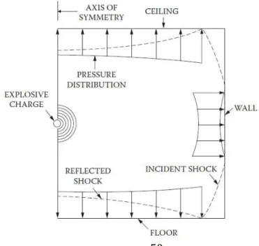
Figure 2.16 Shock reflection from walls during internal detonation (Krauthammer, 2008).. 51
Figure 2.17 Typical pressuretime history in a confined space blast (Krauthammer, 2008). 51
-Figure2.18 - Comparison of predictions with data from the front sensor (Chan, et al., 1994)
………..………... 54
-Figure 3.1- Stress-strain curves at different strain rates for material in which work hardening
rate is (left) insensitive and (right) sensitive to strain rate (adapted from (Meyers,
1994), pp.367) ... 67
-Figure 3.2 - Schematic of a dislocation overcoming barriers with the assistance of a termal
energy (reprinted from (Meyers, et al., 2002) , Copyright 2003, with permission from
Elsevier)… ... 73
-Figure 3.3 - Schematic illustration of the variation of the strain-hardening rate with as a
function of strain rate and temperature. The dashed line shows Voce behaviour
(reprinted from (Follansbee, et al., 1988). Copyright 1988, with permission from
Elsevier). ... 76
-Figure 3.4 - Schematic behaviour of yield stress versus temperature of pure FCC metal
(reprinted from (Voyiadjis, et al., 2008). Copyright 2008, with permission from
Elsevier). ... 79
-Figure 3.5 - Experimental and calculated (fitted) stress-strain curves aluminium at constant
strain rates (reprinted from (Song, et al., 2001), Copyright 2001, with permission from
Elsevier). ... 85
-Figure 3.6 - Comparison of theoretical and experimental values on thermal softening of
30CrMnSiA at a strain rate of 1 s-1 (reprinted from (Chen, et al., 2008). Copyright 2008,
with permission from Elsevier). ... 86
-Figure 3.7 - Experimental (dashed line) and calculated (solid line) shock induced wave profiles
showing the motion of aluminium - PMMA interface versus time for various Pressure,
Temperature and strain dependencies: (a) pure hydro; (b) constant and ; (c) adding
work hardening; (d) adding the dependence of ; (f) adding dependence; (g)
adding the Bauschinger model with ; (h) the Bauschinger effect with
(reproduced with permission from (Steinberg, et al., 1980). Copyright
1980, AIP Publishing LLC)... 88
-Figure 3.8 - Comparison of calculation and experiment for a Ta target shocked to a peak stress of
230 GPa (reproduced with permission from (Steinberg, et al., 1989). Copyright 1989,
-List of Figures
XVII
Figure 3.9 - Comparison of model prediction with the experimental data for annealed OFHC
copper at different temperatures with the strain rate of 4000 s-1 (reprinted from
(Abed, et al., 2005) Copyright 2010, with permission from Elsevier). ... 92
-Figure 3.10 - Predictions of the model and comparison with experimental results for copper at
(a) s-1 and (b) s-1. The calculations for the latter strain rate are for
both isothermal ( dashed line) and adiabatic (solid line) (reprinted from
(Follansbee, et al., 1988) Copyright 1988, with permission from Elsevier). ... 97
-Figure 3.11 - Comparison of model prediction with experimental results for annealed OFHC
copper at different strain rates and temperatures using NNL constitutive model
(reprinted from (Nemat-Nasser, et al., 1998b) Copyright 1998, with permission from
Elsevier) ... 100
-Figure 3.12 - Comparisons between model and experiment for various strain rates and
temperatures: experimental data (dotted), continuum model calculations (dashed) and
model calculations using the present constitutive model (solid) (reprinted from
(NematNasser, et al., 1998a) Copyright 1998, with permission from Elsevier). .... 100
-Figure 3.13 - Comparison of model predictions with experimental results at a strain rate of
3500 s-1 (reprinted from (Nemat-Nasser, et al., 2001) Copyright 2001 with permission
from Elsevier). ... 105
-Figure 3.14 - Description of the flow stress evolution with plastic strain using the MRK model
and comparison with experiments at 4000 s-1 (a) and (b)
(reprinted from (Rusinek, et al., 2010) Copyright 2010, with permission from Elsevier).
... 108
-Figure 3.15 - Fixed-point material velocity profiles for 6071-AA computed using steady wave
analysis are compared to experimental measurements for shock stress amplitudes of
(a) 2.1 GPa; (b) 3.7 GPa; (c) 9.0 GPa; and (d) material velocities profiles plotted on
common axes (reprinted from (Forde, et al., 2009) Copyright 2011, with permission
from Elsevier). ... 113
-Figure 3.16 - Localised strain-rate pattern in a tensile round bar specimen for an imposed strain
rate of 0.002 s-1 (reprinted from [ (Zhang, et al., 2001)] Copyright 2001, with
permission from Elsevier)... 115
-Figure 3.17 - Adiabatic stress-strain curves for OFHC copper, compared with experimental
results at 4000 s-1 strain rates at different initial temperatures (reprinted from
(Voyiadjis, et al., 2005) Copyright 2005, with permission from Elsevier). ... 116
-Figure 3.18 - Comparison of VA model for the stress-strain curve at different strain rates with
experimental data and the NNL model (Nemat-Nasser, et al., 1998b) (reprinted from
-List of Figures
XVIII
Figure 3.19 - Comparison of different models’ predictions with Clifton’s experimental data
(Follansbee, et al., 1988)] for the relation of flow stress versus strain in annealed OFHC
copper at 6.4 x 10⁵ s-1 and room temperature (reprinted from (Gao, et al., 2012)
Copyright 2012, with permission from Elsevier). ... 117
-Figure 3.20 - Model prediction for the relations of flow stress versus strain for OHFC copper
under very high strain rates at room and elevated temperatures (reprinted from (Gao,
et al., 2012) Copyright 2012, with permission from Elsevier)... 119
-Figure 3.21 - Model prediction (solid line) compared with experimental results (circles) for a
compression test for annealed copper (Follansbee, et al., 1988) (reprinted from
(Molinari, et al., 2005) Copyright 2005, with permission from Elsevier). ... 124
-Figure 3.22 - Comparison of experimental stress-strain curves (solid lines) with MJC model
predictions: (a) temperature dependence of flow stress at a reference strain rate of 10
-4 s-1; and (b) effect of strain rate and temperature (reprinted from (Vural, et al., 2009)
Copyright 2009, with permission from Elsevier). ... 128
-Figure 3.23 - Observed and calculated responses for nanocrystalline aluminium at different
strain rates by using KHL model for various grain sizes (reprinted from (Khan, et al.,
2006) Copyright 2006, with permission from Elsevier). ... 133
-Figure 3.24 - The KLF model correlation of the compressive viscoplastic response of 10 h milled
(d = 82mm) bulk Al at different temperatures and dynamic strain rates (Farrokh, et al.,
2009) Copyright 2009, with permission from Elsevier). ... 134
-Figure 3.25 - Stress-Strain correlations between experimental data and constitutive models (a)
strain rate 0.1 s-1; (b) strain rate 1 s-1 (reprinted from (Naderi, et al., 2008) Copyright
2008, with permission from Elsevier) ... 136
-Figure 3.26 - Predicted and measured flow stress for 42CrMo steel under different strain rates
and different forming temperatures: (a) 850˚C; (b) 950˚C; (c) 1050˚C; and (d) 1150˚C
(Lin, et al., 2010) Copyright 2010, with permission from Elsevier). ... 139
-Figure 3.27 - (a) Predicted and measured values of flow stress at a plastic strain of 0.3 for
cold-worked copper as a function of temperature (b) Predicted and measured stress-strain curves
for cold-worked copper as a function of temperature. (Andrade, et al., 1994) Copyright
1994, with permission from Elsevier ... 140
-Figure 3.28 - (a) Comparison between the stress-strain rate behaviour predicted by the
mechanism-based material model and experimental data for 6061-T6, with regions of
the stress-strain rate curve that are dominated by discrete obstacle plasticity and drag
controlled plasticity. (b) Similar comparison for Ti-6Al-4V alloy (reproduced from
(Lesuer, et al., 2001) Copyright 2001; with permission of Lawrence Livermore National
-List of Figures
XIX
Figure 3.29- Formation of an adiabatic shear band in a prismatic body subjected to shear . (a)
Homogenoeus shear strain (b) A shear band is formed (c) Temperarture profiles are
shown were a temperature increase is noticed at the region of the shear band (d)
Stress-strain adiabatic curve showing the softening process after a critical shear strain
is reached. (Meyers, 1994) ... 162
Figure 3.30 Comparison of viscoplastic flow functions. Adapted from (Chaboche, 2008) ... 164
Figure 3.31 The different coordinate systems in the space of principal stresses ... 170
-Figure 3.32- Transition of the failure modes and comparison of the failure loci for AL2024-T351.
Reproduced from (Buyuk, 2013). ... 177
-Figure 3.33 - Failures models on the space described by stress-triaxiality and
Lode-angle-parameter for Al2024-T351: (a) JC model (Johnson, et al., 1985), (b) model by Bao
(Bao, 2003), (c) model by Xue with Lode-angle-parameter (Xue, 2007). Adapted from
(Buyuk, 2013) ... 178
-Figure 3.34 - (a) Bao-Wirzbicki fracture envelope for AL2024-T351 expressed in terms of
equivalent plastic strain to fracture and average stress triaxiality ; (b) The
different types of specimens used for the determination of the fracture envelope (Bao,
et al., 2004) ... 180
Figure 4.1 Typical values of strain rates ((Ngo, et al., 2007) ... 184
-Figure 4.2 - Examples of Lagrangian, Eulerian and ALE approaches. Three sequences are shown
where an initial squared block of material impacts a plate and flattens: In the upper
sequence (Lagrangian approach) the mesh follows the material and distorts severely;
in the second sequence, Eulerian approach, the material flows through a fixed mesh
which remains undistorted and in the third sequence (the ALE approach) the reference
mesh also moves as the material mesh moves to the right. Some element distortion is
observed but material advection is smaller ... 190
-Figure 4.3- Exemplification of ALE procedure: On the left the initial configuration of the
material is shown; on the centre the result of a Lagrangian step is shown: material
deformation has occurred and the mesh has been distorted; on the right the Eulerian
step is illustrated: the new material configuration has been mapped on the mesh to
original position. ... 194
-Figure 5.1 - Schematic representation of the degree of venting of the blast for an explosion
-List of Figures
XX
Figure 5.2 - A meshed model of an Air domain (blue) where a spherical explosive charge (red) at
his centre will be detonated. Only one-eighth of the domain has been modelled. (Mesh
size 147649 elements)... 231
-Figure 5.3 - Numerical and experimental pressure curves read at the same tracer point: a) Using
the alternative advection logic ; b) Using the default advection logic (Parameters used
in each curve are presented in Table 4) ... 234
-Figure 5.4 - The dimensions of the steel bunker and the positions of the pressure sensors in the
experiment of Chan (Chan, et al., 1994) ... 236
-Figure 5.5 - Measured and calculated peak blast overpressures from a confined explosion inside
in a closed steel bunker, (a) Front sensor (b) Lateral sensor (c) Corner sensor.
Pressures in KPa and time in milliseconds. Ref: (Chan, et al., 1994) ... 237
-Figure 5.6 - Diagram of Hu’s experiment for a confined space measuring x, y, z = 50, 30, 40 cm,
where the explosive is on the centre of the floor and a pressure sensor is placed at
coordinates (6,25.5,0)cm. (Hu, et al., 2011) ... 238
-Figure 5.7 - Comparison between numerical and experimental results. The alternative advection
logic defined in LS-DYNA input has been used in the numerical curve. The Autodyn and
experiments curves were reproduced from Hu (Hu, et al., 2011) ... 238
-Figure 5.8 - Comparison between two solutions for the confined TNT explosion described by Hu
(Hu, et al., 2011). The blue solution used an alternative advection logic and the red
solution used the default logic. ... 240
-Figure 5.9 - Comparison between the pressure curve at sensor point xyz (6,25.5,0), in the
confined box described by Hu (Hu, et al., 2011) not using FSI (Curve in red) and using
FSI (curve in blue). ... 242
-Figure 5.10 - Positions of the sensors used to record the pressure-time curves resulting from the
simulated confined explosion in each compartment. ... 244
-Figure 5.11 - Profiles of incident pressure waves arriving at the walls of the closed Box nº 1
(60x60x60cm) (a) in the vertical middle plane of face normal to X (b) in the horizontal
middle plane of face normal to Z. (The incident wave is shown in blue and the first
reflected wave is in red) ... 245
-Figure 5.12 - First arriving wave at the centres of faces – Values of maximum pressures:
Comparison between experimental data and numerical results ... 247
-Figure 5.13 - Variation of peak pressure at corner with the maximum angle between the
standoff direction and any of the three planes crossing at the corner ... 248
-Figure 5.14 - Comparison between the numerical values and two different fits (eq. 15) and (eq.
-List of Figures
XXI
Figure 5.15 - Comparison between the numerical values and two different fits (14) and (18), for
peakpressures at edges and face offcentred points ... 250
-Figure 5.16 – Pressure time history at the centre of the faces normal to x for boxes 1 and 5……….
... 252
-Figure 5.17 - Reflected wave pressure peak at corner (Tracer point 3) for Box nº 2 and explosive
at mid-point of distance between the centroid of the box and face normal to Z (m.kg1/3) ... 254
-Figure 6.1- Test bench for the experiments showing an aluminium plate bolted to the steel
frame. A polyurethane stand supports a PG2 charge (photograph taken before adding
the detonator). ... - 261 -
Figure 6.2 - Dimensions of the steel frames used in the experiments. Thickness of the frames is
18 mm. ... - 261 -
Figure 6.3 - Set-up for the strain gages. Two sets were mounted one each side of the stand in a
full Wheatstone bridge ... - 263 -
Figure 6.4 - Relation between measured values of impulse and deflections at the mid-point of
the plate specimens. ... - 264 -
Figure 6.5 - Mode II tearing at plate experiment 11. ... - 265 -
Figure 6.6 – Thinning and stretching at the plate boundaries in experiment 6 ... - 265 -
Figure 6.7- Dependence of the measured scaled distance , where R is the stand-off distance and W is the mass of explosive (normally its TNT equivalent). ... - 266 -
Figure 6.8 - Relation between the mid-point deflections and the Z scaled distances. ... - 268 -
Figure 6.9 - Illustration of the presence of a cap in plate specimens subjected to larger loading
and closer stand-off distances. ... - 270 -
Figure 6.10 - Finite Element Model of one-quarter of a plate bolted to a steel frame exposed to
the detonation of a high-explosive charge of PG2. ... - 272 -
Figure 6.11- Results of Lagrangian FEA using the *LOAD BLAST ENHANCED function of
LS-DYNA. ... - 274 -
Figure 6.12 - Comparison between the deformed shape and the numerical LBE prediction: (a)
plate 4 and (b) plate 10 ... - 276 -
Figure 6.13 - Comparison between the three FEA approaches and the measured
deflexions……….. ... - 278 -
Figure 6.14 - High localized strains at the edges and holes of the plate samples both observed
and simulated, for plate 6. ... - 279 -
Figure 7.1 - Testing device with two closed chambers separated by an aluminium plate to be
List of Figures
XXII
On the top the cover plate has a movable opening that can be tightly closed and
secured. ... - 284 -
Figure 7.2 – Pressure-time curve recorded in chamber 1 of experiment 22 ... - 289 -
Figure 7.3 – Images of the effect of the detonations on Plate 1, placed between the two closed
chambers: (a) Exp.1 (b) Exp.9 (c) Exp.10 (d) Exp.12 (e) Exp.16 (f) Exp.17 (g) Exp.19 (h)
Exp.20 (i) Exp.21 (j) Exp. 22 ... - 290 -
Figure 7.4 - Pressure time curves at the two adjacent confined chambers for experiment 25……..
...- 294 -
Figure 7.5 - Pressure time curves at the two adjacent chambers at a larger scale, for experiment
25 ... - 294 -
Figure 7.6 - LS-DYNA finite element model of the experimental apparatus ... - 301 -
List of Tables
XXIII
List of Tables
Table 1. 1 - Computer programs for the analysis of load blast in structures (Tang, 2009)……..- 8 -
Table 2.1 – Reproduced from
http://www.globalsecurity.org/wmd/library/report/enviro/eis0157/eis0157_d4.html (Kinney and Graham, 1985) ... 20
Table 2.2 – Combustion reactions occurring during afterburning (Sherkar, et al., 2010) ... 59
Table 3.1 Comparison of the major characteristics of physically based constitutive model. 120
Table 3.2– Constitutive equations of the indicated models ... 121
Table 3.3 Comparison of the major characteristics of some empirical constitutive models 137
Table 3.4 Constitutive equations of the indicated phenomenological models ... 138
Table 4.1 System of units used in LSDYNA ... 199
Table 4.2 TNT parameters for use in *EOS_JWL card ... 202
Table 4.3Plastic explosives parameters for use in *EOS_JWL card ... 202
Table 4.4 Properties used in the *EOS_ LINEAR_POLYNOMIAL card for air ... 204
Table 4.5 Properties of TNT for input in *MAT_HIGH_EXPLOSIVE_BURN card ... 207
Table 4.6 Properties of plastic explosive for input in *MAT_HIGH_EXPLOSIVE_BURN card 207
Table 4.7 Properties of the Air in the *NULL_MATERIAL card ... 208
Table 4.8 Hourglassing parameters for input in ALE mesh ... 210
Table 4.9 Parameters used for the JohnsonCook viscoplastic deformation model ... 220
-Table 5.1- Peak pressure and time of arrival (experimental and numerical) as reported by Alia
and Souli and Kamal and Aquelet: (a) with a mesh of 27972 elements (b) With a mesh
of 56916 elements. ... 233
-Table 5.2 - Free air explosion: results obtained with 2D meshes and different advection logics and
advection methods ... 233
-Table 5.3-Finite element mesh parameters for the simulation of a confined explosion of a
mixture of oxygen and hydrogen in a closed rigid compartment. ... 238
Table 5.4 Box dimensions and characteristics of the meshes used in the simulations ... 241
-Table 5.5 - Position of the explosive charges in each box relative to box dimensions ... 241
-Table 5.6- Position of all sensors for box nº 1 ... 243
-Table 5.7- Comparison between the peak pressures obtained numerically and from equation (17) at
corner sensor no. 3... 249
-Table 5.8- Comparison between the peak pressures obtained numerically from equations (18)
... …. 250
-Table 5.9 - Listing of the highest peak pressures recorded at each case analysed (Note that due to
-List of Tables
XXIV
Table 6.1- Definition of observed failure modes according to Jacob et al. (Jacob, et al.,
2004)……….…. ... - 259 -
Table 6.2- Chemical composition of the AA5083-H111 aluminium alloy………...- 260 -
Table 6.3- Free air blast midpoint deflection results ... - 263 -
Table 6.4- TNT equivalence factors for plastic explosive C4. ... - 267 -
Table 6.5- Scaled distance Z parameter values for the explosive tests assuming a 1.19 impulse equivalence factor for TNT. ... - 269 -
Table 6.6- Johnson-Cook model parameters for AA5083-H111 (Winzer, et al., 2011) ... - 273 -
Table 6.7- Comparison between different element sizes of ALE mesh in the calculation of plate
deflexion from experiment no 1 and CPU time in a i7-2700K CPU @ 3.50 GHz machine
...- 274 -
Table 6.8 - Results for maximum mid-plate deflexions obtained from FEA (LBE). ... - 275 -
Table 6.9 - ALE shell results for plate maximum deflection. ... - 280 -
Table 7.1- Results of experiments of confined explosions in a double chamber divided by an
aluminium plate diaphragm. The experiments considered successful are highlighted in
yellow…. ... - 287 -
Table 7.2 - Experimental results of the second phase placed by the order of increasing Z scaled
distance ... - 291 -
Table 7.3 - Experimental results of the third phase placed by the order of increasing Z scaled
distance ... - 291 -
Table of Acronyms
XXV
Table of Acronyms
AIREX Airborne Explosion
ALE Arbitrary Langrangian-Eulerian
BAZOOKA Portable grenade launcher (EUA)
CJ Chapman-Jouguet
Composition B Hexotol (HE: mixture of TNT and RDX)
Composition C A family of US plastic explosives (HE: mixture based on RDX). The C4 is a 91% mixture of RDX and a plasticizer plus a binder).
CONWEP Conventional Weapons Code
EBC Equivalent Bare Charge
DoD Department of Defence (USA)
EBW Enhanced-blast weapon
EOS Equation of state
FSI Fluid-structure interaction
HE High explosive
HMX Ciclotetrametilene-tetranitramine also known
as Octogen (HE)
JWL Jones-Wilkins - Lee
LAW Lightweight Anti-tank Weapon (EUA)
LE Low explosive
OPNAVINST US NAVY Operations Instruction
PANZERFAUST Tank Fist (in english) Anti-Tank Portable Weapon (ALEMANHA)
PE4 British version of the C4 plastic explosive
PETN Tetranitrate of pentaeritritol (HE)
PG2 Plastic explosive
Table of Acronyms
XXVI
RDX Ciclotrimetilenotrinitramine also known as
Hexogen or Ciclonite (HE)
RPG Routchnoy Protivotankovy Granatomiot
(Anti-Tank grenade launcher) (RUSSIA)
RShG-1 Multipurpose Assault Weapon
RPO-SHMEL Rocket Assisted Flame Thrower (RUSSIA)
SMAW Shoulder-Launched Multipurpose Assault
Weapon (EUA)
TNT Trinitrotoluene, Trotil, Dynamite (HE)
TBX Thermobaric explosive
Chapter 1
- 1 -
1.
M
otivation, objectives and
thesis organization
1.1
Motivation
The study of the effect of blast waves in confined spaces and particularly how those waves are transmitted to neighbouring spaces and what will be the resulting effects, is of interest for the vulnerability assessment of buildings, airplanes and vessels, being for this reason an important subject within the field of security and national defence given the diversity and permanent nature of present threats. In the particular case of ships and smaller craft engaged in the enforcement of the authority of the state at maritime areas under its jurisdiction, it is paramount the knowledge of such vessel’s vulnerabilities and of the risks involved in such missions, notably in missions of prevention and repression of smuggling, traffic of narcotics, arms or human beings or the prevention of terrorist activity or Force and Harbour Protection.
Not only the terrorist threat should be under consideration but also the possibility that organized crime groups are becoming increasingly better equipped and more audacious. Fire engagements at sea with law enforcement agencies or even the navy, may be possible and probable in a near future.
Chapter 1
- 2 -
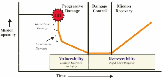
concept of vulnerability is well defined in naval doctrine, for instance as in the OPNAVINST (Department of the Navy, 1988), and relates to the broader concept of survivability. Survivability of a ship is given by her capacity to avoid or resist the damage and to recover the necessary integrity to accomplish her mission. This definition encompasses three components related by:
! " # $ #% " & $' (1.1)
where S is the probability of survival, # is the probability of being hit (susceptibility),
$ # is the conditional probability of loss of capacity to accomplish the mission
(vulnerability) and & $ is the conditional probability of recovering from the damaged condition (recoverability). Fig. 1.1 shows how this survivability process evolves with time.
Susceptibility has to do with those means the ship has to avoid being hit, such as sensors, signature control and decoys or the preventive use of her weapons, and is outside of the scope of this work. The same applies to the analysis of recoverability known in all navies as damage control and more recently as internal battle.
The vulnerability of a ship is thus measured by the conditional probability of the occurrence of a given damage when hit by a certain type of weapon. All vessels have a certain capacity to absorb damage due to systems redundancy, structural resistance and suitable internal arrangement and it is obvious that design decisions influence survivability. Therefore, some guidance or data on vulnerability assessment must be available to the naval architect. This work attempts to give a novel contribution to the vulnerability analysis of ships and small craft. The direct relationship between ship design and ship vulnerability constitutes the incentive to a deepening of all aspects that can provide the designer with guidance and criteria for the design of safer and more resilient vessels.
Chapter 1
- 3 -
overall damage risk mitigation and, eventually, the definition of operational doctrine for the crews operating in small coastal light craft for surveillance and patrol.
Figure 1. 1- Survivability of a damaged ship as a function of time (Webster, 2007).
The present study is restricted to confined explosions, which limits the number and type of the weapons that may constitute the threat. This means that free air explosions have not been considered nor underwater explosions, which constitute a very specific area of research. Stand-off explosions are also outside the scope of this study as the resulting blast would mainly cause external damage. A confined explosion may result from an explosive device left intentionally inside a compartment. This, although unlikely to happen in a military or police vessel, may happen in a passenger or transport vessel. However, portable grenade launchers may represent a very powerful threat. The ammunition fired by the vast panoply of existing launchers sends to the target a relatively significant HE charge, capable of inflicting a large damage in the light structures of those light craft. There are many manufactures of weapons of this kind originating from dozens of countries (LAW, SMAW, BAZOOKA, RPG, PANZERFAUST, CARL GUSTAV, SHMEL; etc). From all these the most widespread is undoubtedly the RPG1, thanks to its low cost, robustness and simplicity. However, most of the available ammunition has contact fuses or are armour-piercing. The first detonates outside the target as an airborne explosion and the second projects to the inside a high energy jet of
1 The RPG 7, worldwide available and regularly owned by terrorist groups, pirates, guerrillas,
Chapter 1
- 4 -
melted metal that in light structures without armour protection will have only a local penetrating effect, propagating as a straight line through the compartment. Both effects will not fit in the concept of a confined blast. We are thus left with HE ammunitions with time fuses that will delay the detonation to a few milliseconds after impact allowing the projectile to penetrate a light bulkhead and to detonate in the inside. Also hand grenades may be considered as possible origins for confined blast. A hit by one of these weapons will result in an internal detonation causing direct damage in the hit compartment and indirect damage in the neighbouring spaces. The amount of damage may vary with other factors than the mass and nature of explosive, such as compartment dimensions, venting, internal arrangement and strength of bulkheads and decks.
As far as the author is aware there is no work published on the subject of damage inflicted in a compartment due to internal blast loading on the adjacent compartment.
1.2
Work methodology
Chapter 1
- 5 -
The numerical analysis of high speed and very intense loading of structures and materials employs, in general, a category of software bearing the traditionally designation of hydrocodes. The designation persisted since the first numerical investigations on high speed impact at the Los Alamos laboratory in the 1950’s. Because the pressures imparted by such impacts were several orders of magnitude higher than the strength of the materials impacted, calculations assumed pure hydrodynamic behaviour of those materials, ignoring deviatoric stresses. In result, material stress tensors would resemble those of fluids and so such codes were baptised as hydrocodes.
Hydrocodes are programs for the computation of continuum mechanics models involving large transfer of energy in short periods of time (blast and impact) and the behaviour of materials subject to very high loading rates (Zukas, 2004). Hydrocodes deal, in latu sensu, with nonlinear problems with time dependence, typically with transient loading and involving large deformations occurring in very small time intervals (Benson, 1990).
They are basically similar to finite element codes developed for structural analysis or solid mechanics but because of the large deformations involved in the analysis, explicit time integration is preferred as well as Arbitrary Lagrangian-Eulerian (ALE) meshes as these will avoid the excessive deformation of a Lagrangian mesh. These options require advection algorithms to transport material between cells as ALE techniques are based on a relative motion between mesh and material. Equations of state (EOS) will also be employed to relate energy, pressure, volume and density. Finally constitutive equations will relate stress, strain, strain rate, internal energy and failure criteria. This will be explained in detail in the following chapters.
All hydrocodes are similar in their structure. They may just resume to a solver but some add pre-processor and post-processing modules for data input and result checking. A flow diagram of a typical hydrocode solver is shown in Fig. 1.2.
Chapter 1
- 6 -
Table 1.1 shows a selection of explicit codes used for blast loading or impact analysis. Setting up an experiment of blast loading is time consuming and expensive due to the destructive nature of the experiments and the degree of sophistication of the equipment required to collect data from the explosion and its effects. This recommends the use of numerical tools where parameter variation can be easily performed for any number of combinations desired. However, numerically modelling a physical phenomenon implies a number of approximations and simplifying assumptions to maintain the complexity of the model within practical boundaries. Numerical tools are also prone to error and validation involves considerable effort and analysis but this disadvantage is largely compensated by the richness of the information that can be obtained through computing. In general trends, parameter relations and comparative results will often be as important as absolute results and this is where the real power of computational tools is unfold.
Small light craft are the main purpose of the intended findings. Small light craft are mainly constructed either of composite materials or naval aluminium alloys. In both cases there are a large number of vessels involved in patrol and law enforcement activities. Typical naval grade aluminium alloy has been used in many high-speed light craft, such as patrol boats, ferries and small passenger vessels and was the choice for the present work.
Chapter 1
- 7 -
Figure 1. 2 - Diagram of blocks of a typical hydrocode (Zukas, 2004). Define geometry of problem (nodes and
elements)
Define properties (materials) of elements
Lump the masses at nodes (diagonal mass matrices)
Definition of nodal initial velocities
Solution of the systems of eq.
Velocities
Displacements Accelerations
Contact algorithm Forces
Chapter 1
- 8 -
Table 1. 1 - Computer programs for the analysis of load blast in structures (Tang, 2009)
Product Analysis type Author or owner
BLASTX Blast loading predictions, CFD,
semi-empirical
SAIC
CTH Blast loading predictions, CFD, first
principles
SANDIA National Labs
FEFLO Blast loading predictions, CFD, first
principles
SAIC
FOIL Blast loading prediction, CFD, first principles Applied Research Associates, Waterways
Experiment Station
HULL Blast loading prediction, first principles Orlando Technology
SHARC Blast loading prediction, CFD, first principles Apploied Research Associates, Inc
DYNA3D Structural analysis, CFD , Coupled analysis,
first principles
Lawrence Livermore National Laboratory
ALE3D Coupled analyis, first principles Lawrence Livermore National Laboratory
LS-DYNA Structural analysis, CFD , Coupled analysis,
first principles
Livermore Software Technology Corporation
EPSA-II Structural analysis, first principles Weidlinger Associates
FLEX Structural analysis, first principles Weidlinger Associates
ALEGRA Coupled analyis, first principles Sandia National Laboratories
Air3D Blat loading predictions, CFD,
semi-empirical
Royal Military College of Science, Cranfield
University
CONWEP Blast loading predictions, empírical US Army Waterways Experiment Station
ABAQUS Structural analysis, CFD , Coupled analysis,
first principles
ABAQUS Inc
1.3
Materials
Chapter 1
- 9 -
alloy, only exceeded by AA5456. The main mechanical properties of this alloy can easily be obtained from manufacturers but some typical values for tensile strength, yield strength and elongation have been reported to be 347 MPa, 261 MPa and 17%, respectively (Borvik, et al., 2004). The amount of magnesium in AA5083 is relatively high, with about 4.5 wt%. Moreover, AA5083 also contains up to 1% manganese, and minor quantities of elements such as iron, copper, zinc, chromium and titanium to improve strength or other characteristics.
The main stream of published work for utilization of these alloys under very strong and high speed impact loading has been for ballistic applications (Corbett, et al., 1996)(Pekutowski, et al., 1996)(Woodward, et al., 1998)(Piekutowski, 1999)(Forrestal, et al., 2000)(Borvik, et al., 2001)(Roeder, et al., 2001)(Warren, et al., 2001)(Borvik, et al., 2004)(Borvik, et al., 2005)(Gupta, et al., 2006)(Gupta, et al., 2007)(Showalter, et al., 2008)(Sorensen, et al., 2008)(Borvik, et al., 2009) (Borvik, et al., 2011)(Jones, et al., 2012)(Iqbal, et al., 2013) and very little studies are available, until very recently, on blast loading of naval structures.
However, hulls must be welded and the heat from welding will affect the mechanical properties of a tempered or work hardened aluminium alloy. In the heat affected zone the softening effect will significantly reduce the values of such properties and it is common procedure in the design of aluminium boats to use 0 temper aluminium (or close). This will avoid the complexity of having to consider different plate properties in way of weldings. AA5083-H111 aluminium alloy is commonly used for naval construction and it has been chosen in the present work.
1.4
Organization of the thesis
Finally to help the reader to navigate within the many subjects that had to be covered a description of how they were ordered is presented.
Chapter 1
- 10 -
lethal radius of the detonation of explosive ordnance inside a given compartment of a ship, for instance.
The focus has been the smaller and lighter craft where, in general, no special shock provisions are considered in their design. It has been necessary to consider a closed space with one of the walls defined with elasto-viscoplastic behaviour and where a HE has been detonated to the point of rupture of that wall. The transfer of energy and blast pressure through the ruptured wall to the adjacent compartment has been modelled and their loading effects measured and compared with those of the first compartment. Experimental results were obtained from field tests with explosives. In a first phase, thin aluminium plates firmly attached to an assumed rigid frame were exposed to free air explosions. The aim was to observe their deformation and calibrate a material constitutive model to be used in the second phase of the experimental program, in which a closed chamber, with two adjacent compartments separated by a thin aluminium alloy plate, was subjected to a confined detonation inside one of the compartments, to cause rupture of the dividing thin plate. Test benches were manufactured specially for the purposes described above and some instrumentation has been used, although budgetary restrictions severely limited the number and type of measuring devices.
The extensive numerical analysis work performed provided a good understanding of the physics of the phenomena involved. Validation has been pursuit by using experimental work published by others, or the direct measured results of the two experimental phases performed under the subject of the thesis.
In all relevant parts of this project a work review has been added, particularly in the part dedicated to constitutive material behaviour where a more thorough review was performed in an attempt to clarify that particular subject, obscured by the profusion of available models.
The organization of the thesis is described as in the following paragraphs:
Chapter 1: Motivation, objectives and thesis organization
Chapter 1
- 11 - Chapter 2: Explosives and blast waves
An introduction on the mechanics and physics of the explosive phenomena is provided, in the depth considered adequate for the understanding of the modelling options followed in the subsequent Chapters. An essential review of the Rankine-Hugoniot relations and basic thermodynamics of explosions are also presented.
Chapter 3: The effect of blast on structures
The response of materials to blast involves plastic deformation, strain rate, hardening and temperature effects and micro-structural changes, which in itself constitutes a very wide field of research. The complexity of the subject required an extensive review which helped to direct the choice of the material model to be used in this very specific, high velocity, high pressure type of loading. Many constitutive relations exist to describe the elastic visco-plastic and failure behaviour of metals and particularly naval grade aluminium plates were described in this work. The main content of the chapter is a review on constitutive models for metals subjected to high strain rate loading.
Chapter 4: Numerical modelling
An extensive numerical analysis was performed implying the input of a significant number of data and various modelling techniques. Such techniques and input are presented and explained together with a theoretical background of the algorithms that have been used in the analysis. ALE theories, fluid-structure interaction, contact algorithms, advection and explicit time-integration are some of the subjects covered together with fundamental aspects of non-linear continuum mechanics theory.
Chapter 5: Confined explosions – a parametric numerical analysis
Chapter 1
- 12 -
Chapter 6: The behaviour of AA5083-H111 plates exposed to free air blast
Since the material chosen for the subject of the thesis was the AA5083-H111 aluminium alloy, it was necessary to investigate its properties under blast loading. This Chapter details the experimental work and the analysis performed to characterize the visco-plastic behaviour of the chosen material. The experimental data obtained from a series of free-air blasts has been used to validate a numerical constitutive model, to serve as the basis for the subsequent and last phase of this work.
Chapter 7: Blast wave transmission between two adjacent, confined compartments
This Chapter presents the experimental work on a set of two closed chambers connected by a AA5083-H111 plate diaphragm, where confined explosive charges were detonated in one of the chambers to observe the effect of the blast in the second chamber after rupturing the diaphragm plate. The experimental data is presented and discussed. The numerical simulations attempting to validate the model are also presented although a complete validation was not possible to be obtained.
Chapter 8: Conclusions
The last Chapter presents the relevant conclusions and the major objectives that were reached as well as those who were not. A final synthesis of the project is presented.
As it can be seen the work presented in each chapter leads the reader through a sequence related to the progression of knowledge:
- The theory behind explosive loading (wave blast, pressure curves, the influence of stand-off distance and confinement); Chapter 2.
- The theory behind constitutive material behaviour under blast loading, including a relatively comprehensive review of high strain rate plasticity and failure of metals; Chapter 3.
- The numerical tools, where the most important numerical technologies necessary to address numerically these problems are explained; Chapter 4 and 5.
Chapter 2
- 13 -
2.
E
xplosives and blast waves
2.1
Nomenclature of explosives
An investigation on the effects of blast loads on plated structures requires a basic knowledge of the physics of the explosive phenomena. It is outside the scope of this thesis to describe the state of art of explosion and shock mechanics but some essential knowledge has been collected to provide a more clear understanding of the whole problem in hand. An accurate modelling of the explosive detonation is a very demanding task requiring a deep knowledge of chemistry. For instance, the constant specific heat ratio γ, of air will change its value at high temperatures and afterburning effects will affect the reflected impulse. The chemical composition of an explosive will govern its physical properties. Most of the data and information gathered in this chapter comes from Sherkar (Sherkar, et al., 2010).
High explosives science couples chemistry and fluid mechanics but although the latter is well understood the detailed knowledge of the chemical reactions and thermomechanics that cause the detonation is still not completely understood. It is not possible to obtain a sample of material when it is being reacted to see how the chemistry is progressing. There is no way of studying the chemicals and their reaction at the detonation front with most laboratory apparatus. More sophisticated techniques such laser spectroscopy may solve many of the difficulties to understand such phenomena.
Chapter 2
- 14 -
motion will be the major driving mechanism for energy transport, rather than heat radiation or conduction or viscosity.
Explosions can be characterized in different ways. The classification criteria adopted here is one of the many possible and starts from a broad division into nuclear, mechanic and chemical explosions. Nuclear and mechanical explosions are outside the scope of the thesis. One example of a mechanical explosion is, for instance, the rupture of an over-pressured vessel when its maximum strength is exceeded causing a sudden and violent expansion of the contained gas.
The usual classification for chemical explosives divides them into low explosives (LE) and high explosives (HE) and this division determined the choice of energetic material to be simulated. We will discard LE which includes powders, rocket and missile fuel and flares as their use is not of interest for this work due to their low reaction speeds. Fig. 2.1 depicts the combination of a primary (HE) explosive used to initiate the detonation of the secondary (HE) explosive.
The classical classification of chemical explosives divides them as shown in Fig. 2.2. Another subdivision can be made in the HE group, into primary and secondary explosives. Primary explosives have reaction speeds of the order of 3500 – 5500 ms-1
Chapter 2
- 15 -
and are very sensitive to initiation by shock, friction or heat, which makes them suitable to be used as fuses and detonators as their detonation will activate the reaction of the secondary explosive. Examples are lead azide, lead styphnate (trinitroresorcinate), lead mononitroresorcinate (LMNR), potassium dinitrobenzofuran (KDNBF) and barium styphnate (Sherkar, et al., 2010). Secondary explosives are more energetic, with reaction speeds in the range 5500 – 9000 s-1 but are much less sensitive and cannot be easily detonated by heat or shock. This difference in stability between primary and secondary explosives requires certified personnel to handle them in the field and strict safety rules to be followed by the research team.
Figure 2. 2- Classification of chemical explosives (Sherkar, et al., 2010).
An explosive is a composition of the type CxHyNwOz and one explosion is a reaction of oxidation where the oxidizer may be, instead of atmospheric oxygen, an oxidizing salt, such as a nitrate or a perclorate belonging to the composition itself. The presence of these products speeds up the oxidation, allowing a very fast reaction with supersonic speeds upto 9000 ms-1. These high speeds are what make the violent nature of detonations when compared with deflagrations, concepts that will be explained later. This supersonic wave velocity is almost constant for a particular explosive but it varies from one explosive to another, depending on the composition and density of the
Explosives
LowExplosive
(LE)
Propellents
Powders,
pyrothecnics,
etc..
HighExplosive
(HE)
Primary
explosives
Chapter 2
- 16 -
explosive. The extraordinary propensity of explosives to react will result in large amounts of energy released during their combustion and being converted to mechanical work in a very strong and damaging loading process. Naturally such reaction is also strongly exothermic and besides its mechanical effect a very hot mixture of gases will also result from the reaction.
Reaction speeds as large as those described above will produce a sudden release of rapidly expanding gaseous products that will compress the surrounding media at such a rate that shock waves will form. These are characterized by a very sharp and high incident pressure that will give the detonation its high destructive power. This release of energy is quite fast as typically 90% of the chemical reaction is complete in no more than one micro-second. During the detonation the explosive will decompose and carbon and hydrogen will react with the available oxygen. The following defines approximately the order of reaction of products (Wilkinson, et al., 2003) :
1. All nitrogen reacts and combines;
2. All hydrogen is used up into the production of water;
3. The available oxygen left after combination with hydrogen reacts with carbon forming CO;
4. The oxygen not reacted in the two processes above reacts with CO to give CO2;
5. The remaining oxygen combines to form molecules; 6. The remaining carbon stays as solid carbon;
7. Remains of NOx are formed.
Thus, CxHyNwOz ⟼xC + yH + wN + zO which will recombine to form the final products of the reaction such as described above.
Many explosives are available (Meyer, et al., 2007)(Dobratz, et al., 1985) and research on new formulations continues in specialized laboratories. They may be grouped into molecular groups such as:
Chapter 2
- 17 - 3. Nitramines;
4. Derivatives of chloric and perchloric acids; 5. Azides;
6. Compounds capable to produce an explosion, such as fulminates, acetylides, nitrogen-rich compounds such as tetrazene, peroxides and ozonides (Sherkar, et al., 2010).
Some examples of secondary HE used in conventional military ordnance but also found in laboratories are presented below:
7. TNT (Trinitrotoluene C7H5N3O6), perhaps the most common;
8. PETN (Tetranitrate of pentaerytrite C5H8N4O12), which combined with TNT gives the well known Pentolite;
9. RDX (US Research Department Explosives - Trimethylenetrinitramine, C3H6N6O6), also known as Hexogen or Cyclonite;
10. HMX (Cyclotetramethylenetetranitramina C4H8N8O8), named also as Octogen (Meyer, et al., 2007).
RDX can be mixed with other compounds to give special purpose compositions. A well known military composition is known as Composition B or Hexotol that is a mixture of RDX e TNT in the proportion 60:40. It is found in grenades and many artillery warheads. Another well known composition is the group of plastic explosives or Compositions C, which can yield very strong detonation rates and show a very high brisance.2 Composition C uses a mix of hexogen and a plasticizer (which may be an explosive itself). The well known C4, for instance, is a military grade mixture of 90% of RDX and 10% of polyisobutyelene, which is a plasticizer. This explosive has the ability to be moulded into a desired geometry thanks to that plasticizer. A close version of C4, the PG2 has been used in the experimental part of this research which is based on 88% of RDX.
2 Brisance is a property of explosives characterized by their destructive fragmentation
Chapter 2
- 18 -
ANFO is also a widely used industrial explosive mixture of ammonium nitrate (AN) and fuel oil (FO). PBX (Polymeric Based Explosive) is presently under investigation as it shows a very good stability and produce a smoother wave front than ordinary HE. Thermobaric explosives or a group of explosives designated by TBX, are a particular case of fuel-air mixtures using aluminium or magnesium cased with the HE.
In some compositions (excepting nitroglycerine and ammonium nitrate) the present oxygen is not sufficient for a complete oxidation and an incomplete reaction will result which imply that an additional energy-release mechanism will contribute to drive the shock front away. The heat generated (heat of detonation) will be lower than the heat of combustion (maximum available energy). The reaction with atmospheric oxygen produces solid oxides and the resulting shock wave is generated by the heat of combustion rather than by the expansion of gaseous oxides that are generated by the combustion of the explosive. This means that the pressures generated will be lower but the reaction will take longer as the unburned products will react with the ambient oxygen producing additional energy, continuing to release heat. This reaction is called afterburning. The available energy in the post-combustion phase is the difference between the heat of combustion and the heat of detonation. For TNT, which has a deficit of oxygen, this difference is about 10.6 MJ kg-1, a lot more than the energy of detonation which is about 4.6 MJ kg-1. But this may show that the energy available for release in the after burn phase is quite considerable although it will depend on the way the products of detonation will expand and mix with ambient oxygen. Adding aluminium powder will allow an after burn (Wilkinson, et al., 2003) and the resulting effect is often designated as an overdriven explosion.