Abstract—One of the biggest concerns in the field of agriculture is around the energy efficiency of robots that will perform agriculture’s activity and their charging methods. In this paper, two different charging methods for agricultural standalone docking stations are shown that will take into account various variants as field size and its irregularities, work’s nature to which the robot will perform, deadlines that have to be respected, among others. Its features also are dependent on the orchard, season, battery type and its technical specifications and cost. First charging base method focuses on wireless charging, presenting more benefits for small field. The second charging base method relies on battery replacement being more suitable for large fields, thus avoiding the robot stop for recharge. Existing many methods to charge a battery, the CC CV was considered the most appropriate for either simplicity or effectiveness. The choice of the battery for agricultural purposes is if most importance. While the most common battery used is Li-ion battery, this study also discusses the use of graphene-based new type of batteries with 45% over capacity to the Li-ion one. A Battery Management Systems (BMS) is applied for battery balancing. All these approaches combined showed to be a promising method to improve a lot of technical agricultural work, not just in terms of plantation and harvesting but also about every technique to prevent harmful events like plagues and weeds or even to reduce crop time and cost.
Keywords—Agricultural mobile robot, charging base methods, battery replacement method, wireless charging method.
I. INTRODUCTION
NEof the biggest concerns in the field of agriculture is around robots that will perform agriculture’s activity not just about their work itself but also about the energy efficiency and their charging methods.
There exists in literature many ways to charge a robot, since the conventional way to the wireless new one [1].
Conventional way does not have problems such as big time to charge the all battery. However, it will consist in a problem as it has, first, cables and consequently it does not enable our robot to continue the job until the process of charging is complete.
With time, there have been numerous variations of this subject which does ameliorate these problems being here were the wireless charging mode comes in. On the other hand,
L. Varandas is with the University of Beira Interior, Rua Marquês d’Ávila e Bolama, 6201-001, Covilhã, Portugal (e-mail: [email protected]).
P. D. Gaspar is with the University of Beira Interior, Rua Marquês d’Ávila e Bolama, 6201-001, Covilhã, Portugal and C-MAST - Centre for Mechanical and Aerospace Science and Technologies, Portugal (corresponding author, phone: (+351)275329759; e-mail: [email protected]).
M. L. Aguiar is with the University of Beira Interior, Rua Marquês d’Ávila e Bolama, 6201-001, Covilhã, Portugal and C-MAST - Centre for Mechanical and Aerospace Science and Technologies (e-mail: [email protected]).
although this technique may diminish these obstacles, it entails others. Within this subject we have a lot of techniques to charge our battery. The most known approach is CC-CV but there are a lot of variants to overcome the limitations that this method imposes. Two mentioned examples throughout the paper are Multistage charging and Pulse Current charging. And of course, it is also very important the battery’s type. The one mostly used nowadays is the Li-ion (lithium ions) battery yet we are going to approach a very recent new type.
This subject is a very concern issue nowadays since we have been having increasingly problems with plagues, weeds and other harmful natural consequences, so it is of great concern to be aware of this and of the possibilities to surpass these problems, not just for farmers but for everyone because each one of us influence the evolution of agriculture.
II. WIRELESS CHARGING:PRINCIPALS,ADVANTAGES AND
DISADVANTAGES
A. Working Principal
The most common operating principal of this type of charger is based on magnetic coupling. We will have in our charger coils that, due to the passage of electric current in the coil wires, creates a magnetic field that in turn will induce a current in the coils of the battery, charging it [1], [2]. A loading based on inductive resonant coupling which allows to carry out the process of charging with a fix centimeters distance between the charger and the device is being developed. This would be a benefit since it would enable to have a protective structure over the charging base. This structure would be important to avoid short-circuit to happen when it rains or to avoid battery explosion when there are very high temperatures.
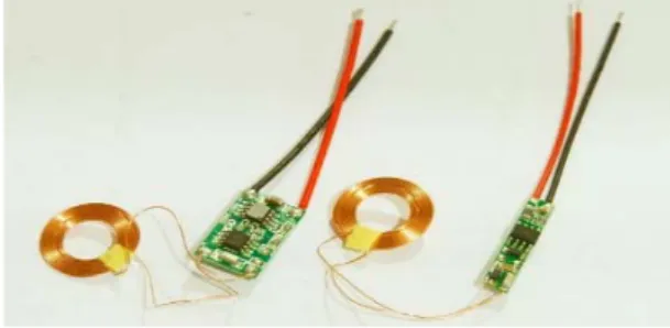
Fig. 1 Wireless charging kit
Fig. 1 shows a wireless charging kit consisting of a transmitter module and a receiver module. Each of them is, in turn, composed of a coil of copper and a dedicated integrated circuit. The transmitter module must be connected to the
Standalone Docking Station with Combined
Charging Methods for Agricultural Mobile Robots
Leonor Varandas, Pedro D. Gaspar, Martim L. Aguiar
O
mains via an AC/DC converter [1].
Our robot has the battery attached, not needing to be removed for charging, and it must remain in the base during the process.
B. Advantages
Wireless charging has the advantage of not using cables, which makes charging not only more accessible but also eliminates one of the most common flaws in this field, damaging connectors [1].
C. Disadvantages
A disadvantage could be the increase in the charging time [1] and consequently of energy consumption due to the losses associated with the wireless transmission [2] as well as we can no longer use the device while it charges.
III. BATTERY REPLACEMENT CHARGING
A. Working Principal
The most common operating principal of this type of charger is based on battery replacement. The robot will reach the charging base and its low battery will be exchanged by a new one fully charged, as shown in Fig. 2 [3]. Fig. 3 shows a representation of the rotation mechanism to change the battery.
(a) Rear view (b) Frontal view
Fig. 2 Representation of the charging base B. Advantages
Battery replacement charging has the advantage of not being need to our robot to stop working while is being charged enabling faster results.
C. Disadvantages
A disadvantage will be the need for cables and a larger battery to feed the charging base.
Fig. 3 Representation of the rotation mechanism
IV. BATTERY CELL TYPE
Normally the most reliable cell to use, and the most used
one, is Lithium (Li-Ion) battery. Among all the metals used in batteries, lithium is the lightest, which has the highest electrochemical potential and which provides the highest energy density. They also store twice as much energy compared to NiMH batteries and three times as much as NiCd batteries [4]. Initially, an anode (negative electrode) of lithium metal was used, but it was quickly realized that the charge and discharge cycle caused transformations in this electrode that reduced thermal stability and caused potential thermal leakage conditions. This led to the cell temperature increasing until near the melting point of the lithium. Therefore, lithium-ion batteries have recently been used [4]. The advantages and disadvantages of this battery cell type are described below as stated by [4]:
A. Advantages
1) High energy density; 2) Low maintenance; 3) No memory effect;
4) Relatively low self-discharge, approximately half that of NiCd and NiMH batteries;
5) High voltage, above 3 V, allows the manufacture of batteries consisting of only one cell. This is the case with many mobile phones nowadays;
6) They cause less damage to the environment when discarded, compared for example with lead-acid or cadmium batteries.
B. Disadvantages
1) It requires larger currents to maintain the same energy as lithium metal batteries, hence usually have a lower resistance to allow more current flow;
2) Requires a protection circuit that limits voltage and current. Embedded within each set, the protection circuit limits the peak voltage of each cell during charging and prevents the cell voltage from dropping too much during discharge. In addition, the maximum charge and discharge current is limited and the cell temperature is monitored to prevent extreme temperatures;
3) Subject to aging even when not in use; 4) The electrolyte is highly flammable; 5) Expensive manufacturing.
V. NEW GRAPHENE BATTERY
Recently a team of SAIT researchers developed a “ball of graphene” this being a unique material for allowing the increase of the capacity of the battery in 45% in addition to still increase in 5 times the speed of loading when compared with the batteries of lithium-ion. Compared with li-ion batteries, graphene was used for both the anode protective layer and the cathode materials being this what allowed an increase in the loading capacity and decrease of its time as well as stable temperatures [5].
Graphene was initially chosen because of its high strength and conductivity features. A mechanism has been developed to synthesize graphene in 3D, like a popcorn, through silica [5].
VI. BATTERIES:COMMON PROBLEM AND SOLUTION
Firstly, to develop this topic, it was necessary to define a base voltage value, for each battery, of approximately 20 V. Throughout this point, two main problems have arisen. The first is related to the batteries ’voltage. As it was approached previously our batteries are constituted by cells which one having approximately 4.2 V meaning that the battery must present several cells working simultaneously to make the necessary 20 V, i.e. we must connect several batteries in series [6].
The first problem gets solved, but, nevertheless, it entails a second problem which is the difference between the voltage of each cell during and after charging (see Fig. 4). This is due to both intrinsic and extrinsic changes to these cells being the intrinsic differences small variations in the process of building the cell that lead to different capacities, volume, internal impedance and discharge rates, which with increasing charge and discharge cycles worsen. This happens because when having batteries with different charge levels/characteristics, when charging simultaneously, batteries will charge faster than others. Some of these batteries may already be close to their charge value, but as this is not happening with all cells charging continues to be done blasting the batteries that exceed the maximum value and spoiling the battery in general [6]. To solve this problem, a batteries balance must be performed. This concept, as the name implies, is intended to distribute the current between the cells so that they are all loaded at the same level [6]. There is active and passive balancing. To achieve passive balancing, we monitor our batteries through a Battery Management Systems (BMS), whose main function is to monitor and control parameters such as voltage, current and temperature. The applied BMS has a balancing methodology called the switched shunt resistor, as it is based on a bypass cell methodology where each cell that is in the constitution of the battery is associated with a balancing resistor and a switch. This balancing then consists of discharging the battery when it is not being used (Fig. 5 (a)) or providing an alternative path for the current while the battery is being charged until all the batteries have reached the same level of charging, i.e. until all have the same voltage (Fig. 5 (b)) [6].
Fig. 4 Representation of cells’ state of charge
(a) BMS – open circuit. (b) BMS – closed circuit Fig. 5 Representation of the main and alternative current paths [6]
As for active balancing, it can have several topologies that are classified into two groups, one based on the use of capacitors and the other on the use of converters, and this second group can be further divided into isolated or non-isolated [6].
The main drawbacks are the dissipation of energy over the form of heat and the fact that the balancing influences the voltage readings, so it is necessary to add a certain delay time [6].
VII. BATTERY ENERGY MANAGEMENT
A. CC-CV Charging Method
This method of loading, constant current/constant voltage (CC/CV), is very referenced in the literature due to its simplicity and ease of implementation [7].
It has two operating phases, as shown in Fig. 6 [7].
In the first stage the cell is subjected to a constant current stage, with a fixed and predetermined value, depending on the specifications of the cell [8]. Once the cell voltage reaches the charge value (typically 4.2 V for the Li-ion cell) the algorithm switches to the second phase of the charge. At this stage, the cell is subjected to a constant voltage. When the current reaches a preset value or the maximum charging time is reached, the charging is concluded [8], [9]. See Fig. 6 for details.
Fig. 6 CC-CV charging algorithm [7]
The disadvantages of this method are the charging time. Variants of this method that overcome these disadvantages can
be found in the literature.
B. Multistage Charging Method
This multi-stage charging method is characterized using n current stages as shown in Fig. 7 with five stages [7]. The use of this charging method raises two questions, the first one is the criterion used to exchange current stages, the second is the
determination of the appropriate current stage that must be applied at each instant of time [8].
One of the solutions used in the literature, consists of the criterion used in Fig. 7, where change of stages occurs as soon as the voltage of the cell reaches Vload [7].
Fig. 7 Multistage charging algorithm [7]
As for the determination of the appropriate current stages, the solution passes through the application of optimization algorithms. For example, the PSO algorithm and fuzzy controllers must be applied at each instant of time, depending on the "choice" of charging time and cell capacity [7].
In this multistage method, the last stage is carried out with constant voltage (CV) to determine the optimum load profile. This method achieves a reduction in the charging time that varies between 11.5% (with four stages) and 18.27% (with 20 stages) when compared to the CC/CV algorithm [7].
C. Pulse Current Charging Method
This method of charging is characterized using a pulsed current and can be subdivided into two Variable Frequency Pulse Charge (VFPC) and Variable Duty Pulse Current (VDPC) [8], [10].
In VFPC the objective is to optimize the frequency of the current pulse, minimizing the impedance of the cell and consequently maximizing the transfer of energy. As for VDPC this consists of maximizing the energy transfer through two approaches, either by varying the pulse width by fixing the pulse width or by varying the pulse width by setting the amplitude [7].
Usually both will be composed of three modes of operation, full charge detection mode (FCDM), search mode (SM), and charge mode (CM) [11]. Initially, it begins with the MGDF, detecting the state of the cell, for that a constant voltage is applied to the cell to monitor the charging current. After completing this step, we switch to the SM mode of operation by discovering the optimal frequency and PWM. As soon as the frequency is "optimized" the algorithm enters CM mode of operation, repeating this process until the cell is charged. Per the experimental results, the proposed algorithm, when compared to the CC/CV algorithm achieves a reduction in the loading time in the order of 24% [7].
VIII. BATTERY LIFE AND CHARGING TIME
Focusing on the Li-ion batteries for these calculations, as they are more studied than the new batteries of Samsung, knowing that each cell usually has 4.2 V and wanting a battery for our robot of approximately 20 V, 5 A and 100 W we need of five cells in series to form this battery each traversed by 5 A. Knowing also that each battery has in standard 3000 mAh our battery would last only: (3/5)×60 = 36 minutes.
Subsequently should be made the appropriate conversions for the battery that we will use given its size and consequently the number of cells that it will have, 40 cm × 20 cm × 15 cm, because the more cells the greater the capacity of the battery.
The charging time of all Li-Ion batteries, when charged to an initial current of 1 C, is approximately 3 hours.
Considering that the new batteries of Samsung have a capacity 45% higher than those of Li-ion we can say that they will last longer and considering that they charge 5 times faster, in this example given above we can assume that they will last about 36 minutes charging.
IX.ATTACHMENT DEVICE
There are several approaches to this issue, with only two in this project.
It should always be possible to connect the battery to the base regardless of whether the robot is well positioned, since we are going to work with unstable ground and there is always this possibility. For this to be achieved, the robot must have a system that allows it to detect connection failures so that it makes several attempts until the connection can be made.
A. First Method
In this method, the connection is made from parts that are tightened inside a circular port. Then the battery is pulled in and the parts expand to release [3]. The same thing happens in the next process of placing the battery in the robot.
B. Second Method
This method consists of an electromagnetic connection system, having electromagnets with different polarity from the connection system for the batteries, and functions like a magnet.
The pulling piece is disconnected from the battery by turning off the system that induces magnetization.
X. CONCLUSION
Although the limitations, the use of graphene battery charged with CC-CV method seemed to be one of the best approaches regarding the profitability, effectiveness and lower costs that this is going to bring on to the agricultural field.
All studies were focused mostly on the Li-ion battery concepts [4], [8]-[10]. Since we have more information about this type of battery, the concepts were developed to a graphene battery type.
Knowing that Li-ion batteries require at least 1h to fully charge even with fastest charging technology implemented and that for the same conditions a graphene battery only requires 12 minutes and even maintains a stable temperature, we can conclude that it is more effective to use these new batteries rather than using a more evolved but more problematic and expensive charging method.
A future study could be in terms of preventing the losses in wireless charging method thus preventing large energy consumption. Other study could be in terms of combining the new graphene battery with a more efficient charging method, even though it could still have limitations of other nature.
ACKNOWLEDGMENT
This study is within the activities of project PrunusBot - Sistema robótico aéreo autónomo de pulverização controlada e previsão de produção frutícola (autonomous unmanned aerial robotic system for controlled spraying and prediction of fruit production), Operation n.º PDR2020-101-031358 (leader), Consortium n.º 340, Initiative n.º 140 promoted by PDR2020 and co-financed by FEADER under the Portugal 2020 initiative.
REFERENCES
[1] S. Das, A. Wasif, N. Kumar, and E. Karim, “Wireless powering by magnetic resonant coupling : Recent trends in wireless power transfer system and its applications,” Renew. Sustain. Energy Rev. 51, pp. 1525– 1552, 2015.
[2] A. Agbaeze, S. Kamal, A. Rahim, C. Yen, and S. Jayaprakasam, “Low-power near- fi eld magnetic wireless energy transfer links : A review of architectures and design approaches,” Renew. Sustain. Energy Rev. 77, pp. 486–505, 2017.
[3] M. Bonani, V. Longchamp, R. Philippe, D. Burnier, G. Roulet, F. Vaussard, H. Bleuler, and F. Mondada, “The MarXbot , a Miniature Mobile Robot Opening new Perspectives for the Collective-robotic Research,” in Proceedings of the 2010 IEEE/RSJ International Conference on Intelligent Robots and Systems, pp. 4187–4193, Taipei, Taiwan, Dec, 2010.
[4] A. Khaligh, S. Member, Z. Li, and S. Member, “Battery, Ultracapacitor, Fuel Cell, and Hybrid Energy Storage Systems for Electric, Hybrid Electric, Fuel Cell, and Plug-In Hybrid Electric Vehicles: State of the Art,” IEEE Transactions on Vehicular Technology 59(6), pp. 2806– 2814, 2010.
[5] I. H. Son, J. H. Park, S. Park, K. Park, S. Han, J. Shin, S. Doo, Y. Hwang, H. Chang, and J. W. Choi, “Graphene balls for lithium rechargeable batteries with fast charging and high volumetric energy densities,” Nat. Commun. 1561, pp. 1–10, 2017.
[6] J. Faria, J. Pombo, S. Mariano, and R. Calado, “Power Management Strategy for Standalone PV applications with Hybrid Energy Storage System,” Proc 18th IEEE International Conference on Environment and Electrical Engineering IEEE EEEIC18), Palermo, Italy, 2018.
[7] J. P. D. Faria, “Estratégias de Operação para Sistemas Fotovoltaicos com Armazenamento Híbrido de Energia Elétrica,” Dissertação de Mestrado em Engenharia Eletrotécnica e de Computadores, Universidade da Beira Interior, 2018.
[8] W. Shen, T. T. Vo, and A. Kapoor, “Charging Algorithms of Lithium-Ion Batteries : an Overview,” Proceedings of the 2012 7th IEEE Conference on Industrial Electronics and Applications (ICIEA), pp. 1567–1572, Singapore, Republic of Singapore, Nov., 2012.
[9] A. A. Hussein and I. Batarseh, “A Review of Charging Algorithms for Nickel and Lithium Battery Chargers,” IEEE Transactions on Vehicular
Technology 60(3), pp. 830–838, 2011.
[10] M. Di Yin, J. Cho, and D. Park, “Pulse-Based Fast Battery IoT Charger Using Dynamic Frequency and Duty Control Techniques Based on Multi-Sensing of Polarization Curve,” Energies 9(3), pp. 209, 2016. [11] L. Chen, “A Design of an Optimal Battery Pulse Charge System by
Frequency-Varied Technique,” IEEE Transactions on Industrial
Electronics 54(1), pp. 398–405, 2007.

![Fig. 6 CC-CV charging algorithm [7]](https://thumb-eu.123doks.com/thumbv2/123dok_br/19169943.940783/3.892.457.814.246.366/fig-cc-cv-charging-algorithm.webp)
![Fig. 7 Multistage charging algorithm [7]](https://thumb-eu.123doks.com/thumbv2/123dok_br/19169943.940783/4.892.223.674.255.474/fig-multistage-charging-algorithm.webp)
