REFERENCES
1. V. Veselago, The electrodynamics of substances with simultaneously neg-ative values ofand, Soviet Physics Uspekhi 10 (1968), 509 –514. 2. G.V. Eleftheriades, O. Siddiqui, and A.K. Iyer, Transmission line
mod-els for negative refractive index media and associated implementations without excess resonators, IEEE Microwave Wireless Compon Lett 13 (2003), 51–53.
3. I. Lin, M. DeVincentis, C. Caloz, and T. Itoh, Arbitrary dual-band components using composite right/left-handed transmission lines, IEEE Trans Microwave Theory Technol 52 (2004), 1142–1149.
4. D.R. Smith, W.J. Padilla, D.C. Vier, S.C. Nemat-Nasser, and S. Schultz, Composite medium with simultaneously negative permeability and per-mittivity, Phys Rev Lett 84 (2000), 4184 – 4187.
5. J.-H. Park, Y.-H. Ryu, and J.-G. Lee, A novel planar left-handed transmis-sion line using grounded rectangular patch with meander line, In: IEEE Antennas and Propagation Society International Symposium, Albuquerque, NM 2006.
6. Y. Sun and Y. Zhang, A novel zeroth-order filter based on crlh trans-mission line, Transtrans-mission Lines Antennas 266 (2006).
7. J.D. Baena, et al., Equivalent-circuit models for split-ring resonators and complementary split-ring resonators coupled to planar transmission lines, IEEE Trans MTT 53 (2005).
8. C. Nguyen, Analysis methods for RF, microwave, and millimeter-wave planar transmission line structures, Wiley, New York, NY 2000. 9. D.M. Pozar, Microwave engineering, Wiley, New York, NY 1998.
© 2009 Wiley Periodicals, Inc.
BULK AND PATCH FERRITE
RESONATOR ANTENNAS BASED ON
THE CERAMIC MATRIX COMPOSITE:
GDIG
XYIG
1–XP. B. A. Fechine,1A. F. L. Almeida,2R. S. de Oliveira,3
R. S. T. Moretzsohn,4R. R. Silva,4and A. S. B. Sombra4
1Departamento de Química Analítica e Físico-Química, Universidade
Federal do Ceara´ - UFC, Campus do Pici, CP 12100, CEP 60451-970 Fortaleza, Ceara´, Brazil; Corresponding author: [email protected]
2Mestrado em Cieˆncias Físicas Aplicadas, Universidade Estadual do
Ceara´, Campus do Itaperi 1700, CEP 60740-903 Fortaleza, Ceara´, Brazil
3Departamento de Física, Universidade Estadual do Ceara´ - UECE,
Fortaleza, Ceara´, Brazil
4Laborato´rio de Telecomunicac¸o˜es e Cieˆncia e Engenharia de
Materiais (LOCEM), Departamento de Física, Universidade Federal do Ceara´ - UFC, Fortaleza, Ceara´, Brazil
Received 21 January 2009
ABSTRACT:In this study, the dielectric properties of the
GdIGXYIG1–Xferrite composite material at radio frequency (RF) and microwave frequency bands were studied. These measurements were carried out in different sample geometries: thick films and cylindrical ceramic bulk ferrite resonator. In the RF range, we observed that the material is rather stable because of its short changes as a function of temperature and frequency range. The temperature capacitance coeffi-cient values for all the samples (thick films and cylindrical ceramic bulk samples) presented short positive values at the RF range. The
GdIG0.5YIG0.5thick film was used as a substrate for the microstrip tenna device, where the upper Ag electrode served as a circular patch an-tenna and a microstrip line was used as a feed line. The microstrip anan-tenna operates in this configuration at 8.185 GHz. In the study of the dielectric properties of the composites antenna geometry, with the same ferrite com-posite, a bulk cylindrical geometry was investigated. A numerical study,
together with the experimental, was done, and the dielectric characteristics of the composite liker, tg␦E, andrwere obtained.© 2009 Wiley Pe-riodicals, Inc. Microwave Opt Technol Lett 51: 1595–1602, 2009; Published online in Wiley InterScience (www.interscience.wiley.com). DOI 10.1002/mop.24395
Key words:microstrip antenna; ferrite resonator antenna; microwave devices; temperature coefficient of capacitance
1. INTRODUCTION
In the high-performance mobile radio and wireless communications, low-profile antennas may be used. Low-profile dielectric resonator antennas [1] and microstrip antennas are the natural candidates for these applications [2], especially microstrip antennas. These are stud-ied because of their conformal and simple planar structure. Thus, the microstrip antenna can be fabricated using printed circuit (photolitho-graphic) techniques. This implies that the antenna can be made conformable, and potentially, at low cost. Other advantages include easy fabrication into linear or planar arrays and easy integration with microwave integrated circuits [3]. The development of the microstrip antenna has been expanded into three major program areas: mobile satellite (MSAT) communication, earth remote sensing, and deep-space exploration [4].
Ferrites are employed in a wide range of applications and have contributed materially to advances in electronics. In addition to the advent of new developments such as radar, satellite communica-tions, memory, and computer application, there has been corre-sponding growth in consumer markets in radio, television, video tape recorders, and the Internet [5]. The major advantage of soft magnetic ceramics, compared with their metal counterparts, is that they are electrical insulators. This property is fundamental in keeping eddy current losses low and is one of the main reasons why the major applications of magnetic ceramics have been in areas where such losses have to be minimized [6].
Spinel ferrite was the first magnetic ceramic used in microwave applications. However, the losses for the garnets are smaller than for the spinel ferrites, and for this reason, the garnets are preferred in many applications. YIG (yttrium iron garnet, Y3Fe5O12) is an
example of the garnet ferrimagnetic ceramics widely applied in passive microwave devices. It belongs to a group of magnetic oxides, characterized by specific magnetic and magneto-optical properties. The crystal structure has a cubic symmetry, which is formed by eight formula units, and it belongs to the space group Oh
10—Ia3d [7]. It was prepared for the first time by Bertaut and
Forrat [8], and it was studied in detail by Geller and Gilleo [9]. In this article, we study the dielectric properties at radio fre-quency (RF) and microwave frefre-quency of the composite thick film obtained by screen-printed technique and bulk samples of garnets based on Y and Gd. The films were fabricated from two different garnet ferrimagnetic phases: YIG and GdIG (gadolinium iron garnet, Gd3Fe5O12). Antenna experiments for microstrip and
cy-lindrical bulk resonator antennas were performed. A numerical study of both the antennas operation was realized in conjunction with the experimental measurements. The study of the electrical properties of the ceramic matrix composite based on the garnet ferrite structure was also performed.
2. EXPERIMENTAL METHODS
2.1. Ferrimagnetic Phases
Stoichiometric mixture of Y2O3 (99.99%, Aldrich) and Fe2O3
(99.00%, Aldrich) was used in the YIG preparation. The material was grounded on a Fritsch Pulverisette six-planetary mill in sealed stainless steel vials (221.69 cm3) and balls (Ø 10 mm), under air,
Mechanical alloying was performed by milling for 1 h at 370 rpm. After this, the powder was subjected to calcination under air at 1150°C for 5 h. The reaction that occurs during calcination can be summarized as follows:
3Y2O3⫹5Fe2O332Y3Fe5O12(YIG)
Mixture of Gd2O3 (99.9%, Fluka) and Fe2O3 (99.0%, Aldrich)
powder had the same treatment as that used by YIG starting materials. However, this mixture powder was subjected to calci-nation under air at 1250°C for 5 h. The reaction that occurs during calcination can be summarized as follows:
3Gd2O3⫹5Fe2O332Gd3Fe5O12(GdIG)
2.2. Preparation of the Thick Films
A paste was prepared from the suspension of organic material (Epo´xi, Vantico/Brascola LTDA) to improve rheological behavior of the paste and powders (GdIG⫹YIG), in the ratio of 30:70. For a better adhesion between the paste and the substrate, 5% of a mixture (71.82 mmol of B2O3(99.0%, Aldrich) and 10.73 mmol of
Bi2O3 (99.9%, Aldrich)) homogenized for 10 h by milling [10]
was added to the paste. Alumina (Al2O3) substrates were used as
a commercial product. The electrode material was produced by the screen-printing technique (Joint Metal-PC200).
The bottom electrode (Ag) was screen printed on the Al2O3
substrate and fired at 850°C for 1 h. On the fired electrode, two film layers were screen printed and sintered by the firing process: 100°C for 1 h⫹400°C for 1 h⫹900°C for 1 h (for both layers). After firing the dielectric layer, the upper electrode (Ag) was deposited and dried. Five ferrimagnetic thick film composites were prepared. The GdIGXYIG1–Xnomenclature was used to differen-tiate the composites, whereX(1, 0.75, 0.5, 0.25, and 0) was given in weight percent. The thickness of the obtained films ranges from 221 to 378m.
2.3. Preparation of the Bulk Samples
The bulk samples were prepared in cylindrical geometry, in the same composition of the thick film samples. However, 5% of the suspension of organic material (99.5%, glycerol, bidestilade glyc-erin—O. Moreira & Cia Ltda) was added. This mixture was compacted in a cylindrical mold of 1.5 cm of diameter and sub-jected to a pressure of 111 MPa. After this, the green bodies were sintering at 1250°C for 12 h. The nomenclature of the bulk samples was the same as that used for thick films, and the thickness ranges from 698 to 1901m.
2.4. Preparation of the Ferrite Resonator
Ferrite resonator was fabricated with geometry⬃2:1 (diameter: thickness) in the same process used for ceramic bulk sample (Section 2.3). This dimension was desired to obtain a good elec-tromagnetic match of the TE011mode to be measured by Hakki–
Coleman experiment. Ferrite resonator was labeled with the same nomenclature used to label the thick films and bulk samples.
2.5. Electrical Measurements at RF
The Solartron—SI120 (material impedance material) was used for the dielectric measurements at RF. The obtained data had been adjusted by straight lines, showing a possible linear behavior of the capacitance with temperature in the frequency of 1 kHz and 1 MHz. The temperature coefficient of capacitance (TCC) was cal-culated by the following formula:
TCC⫽关共C共T2兲⫺C共T1兲兲兴/关C共T1兲共T2⫺T1兲兴
whereC(T1) is the measured capacitance atT1(whereT1is 25°C),
andC(T2) is the measured capacitance atT2(whereT2is 100°C).
2.6. Electrical Measurements at Microwave Frequency
The dielectric properties at the microwave frequency were studied using the Hakki–Coleman’s method, based on the resonant TE011
mode. The measurements were done using a HP 8716ET network analyzer [11–14]. From the resonant frequency of the TE011mode,
the dielectric permittivityrand loss tg␦Eare obtained. The values
obtained in this experiment are used as a guide in the numerical simulation of the antennas, with the assumption that the variation ofrwith the frequency is not high between 7 GHz (mean resonant
frequency of the Hakki–Coleman experiment) and 4 GHz (mean resonant frequency of the antenna experiment).
2.7. Antenna Experiment and Numerical Simulation Procedures
The resonant frequency of the microstrip antennas (thick films) was measured using a HP 8716ET network analyzer and measur-ing the return loss (in dB) through the S11scattering parameter of
the antenna being tested.
The simulations of the microstrip antenna and ferrite resonator antenna (FRA) were performed using the Ansoft’s high-frequency structure simulator (HFSS), a software package based on the finite element method. The numerical validation of the experimental setup was an objective of this study. First, the influence of the probe on the resonant frequencies was investigated. Besides, the high sensitivity of the results as a function of the air gap can be confirmed. Finally, HFSS software provides the radiation patterns of the antennas under investigation.
2.7.1. Model of the Microstrip Antenna The configuration of the microstrip antenna is shown in Figure 1 (dimensions 1.26 cm⫻ 1.26 cm and thickness 4.80 mm; commercial products from En-gecer, Brazil). The upper Ag electrode served as a circular patch antenna, and a microstrip line was used as a feed line, where radius
a, dielectric constantr, and heighth(or thickness of the thick
film, in this case) are shown.
The patch antenna is fed by a microstrip line in direct contact with the circular patch conductor of radiusa(see Fig. 1). There are several models related to the planar patch antenna analysis, such as transmission line model, cavity model, and full-wave analysis [2]. Microstrip antennas resemble dielectric loaded cavities. A well-accepted model is detailed in [2, 15]. The transmission line model approaches the microstrip antenna as two slots separated by a low-impedance transmission line (the patch). For the circular patch, one has to consider the fringe field: fringing makes the patch look electrically larger, and so it is necessary to introduce a radial correction factor using an effective radiusaeff, instead of using the
physical measured value of the radiusr [16]. For the dominant mode TM110, which is the dominant mode with the lowest
fre-quency, the resonant frequency is given by [16, 17]:
fr⫽
1.8412.c
2aeff
冑
rr(1)
wherefris the measured resonance frequency,cis the velocity of
light in the vacuum,r is the dielectric constant, andaeffis the
effective patch radius given by [16]:
aeff⫽a䡠
再
1⫹ 2䡠h䡠a䡠rr䡠
冋
Ln
冉
䡠a2䡠h
冊
⫹1䡠7726册冎
1 2
whereris the physical patch radius, andhis the substrate thick-ness. After mathematical manipulation, the dielectric constant is given by [15]:
r⫽
冉
1.8412䡠c 2䡠䡠a䡠fr䡠
冑
r冊
2
⫺ 2䡠h 䡠a䡠r
再冋
Ln
冉
䡠a2䡠h
冊
⫹1.7726册冎
(3)
For the measurements, in this work, we have used a circular microstrip antenna with a ⫽ 0.5 mm and h ⫽ 378.1 m (see Fig. 1).
The resonant frequency is precisely measured using a network analyzer and measuring the return loss (in dB) through the S11
scattering parameter of the antenna under test. The very precise resonant frequency identification is done through the lowermost point in the S11curves (see Figs. 6 and 7). The S11test is the main
test for the antennas. This parameter shows the reflections of the signal at the feeding point, the entrance of the antenna. High negative values (typically between⫺12 and⫺40 dB) in the dip indicate that the electromagnetic waves were not reflected. It means that the antenna is radiating. In the⫺10 dB line, there is an antenna bandwidth (BW; almost equal to VSWR: 2:1). The BW of the antenna (which varies approximately as (K)⫺p, where
p(p⬎1) depends on the mode) decreases with an increase in the dielectric constant. BW (%) is determined from (⌬f/fr)䡠100%, where⌬f(BW) is the 10 dB BW of the resonance (see Table 4). With this data, the antenna personnel might be able to estimate the radiation perfor-mance to a certain degree. The r value is extracted from the numerical procedure using HFSS.
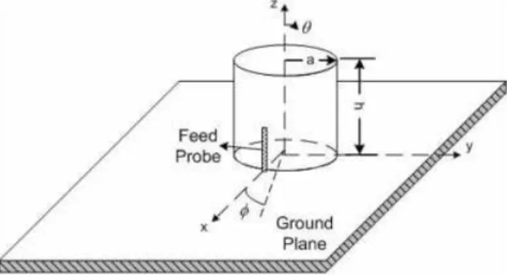
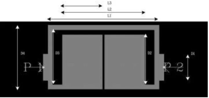
2.7.2. Ferrite Resonator Antenna The GdIG0.5YIG0.5 composite
was selected to make a ferrite resonator to be used as antenna. This resonator was excited by a probe ground plane (see Fig. 2) [18]. The configuration of the cylindrical FRA is shown in Figure 2. The FRA is placed above a conducting ground plane, which is made of copper (with 35.5 cm ⫻ 30 cm⫻ 2.14 mm) and excited by a coaxial probe (L⫽ 9 mm). The coaxial probe goes through the ground plane and is connected to a SMA connector. The probe is located on thexaxis atx⫽aand⫽0°.
The cylindrical FRA work at the HE11␦mode, whose resonant
frequencyfrcan be approximated [19] by the following equation:
fr⫽
2.997⫻108
2
冑
rr冑
冉
1.841
a
冊
2 ⫹
冉
2h
冊
2(4)
This Eq. (4) is obtained with the hypothesis that the lateral and upper surface of the ferrite resonator is perfect magnetic conduc-tor. Because this assumption is verified only for infinite permittiv-ity, (4) is only an approximation that leads to some 10% errors.
3. RESULTS AND DISCUSSION
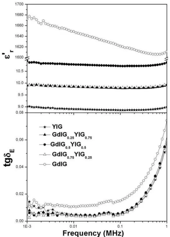
Figure 3 shows the experimental measurements of the dielectric permittivity (r) and dielectric loss (tg␦E), of the thick-film
ferri-magnetic composites (GdIGXYIG1–X) at room temperature. The GdIG0.5YIG0.5composite presented the highestrvalue, probably
because of its good grain distribution between GdIG and YIG phases in the film.rof the GdIGXYIG1–Xthick-film composites varied from 5.0 to 6.5, and the tg␦E values were small (10⫺2 to
10⫺4) and almost constant until 0.1 MHz. Table 1 shows the r⬘
and tg␦Eat 1 kHz and 1 MHz of the composites.
Figure 4 and Table 2 showsrand tg␦Efor the bulk composite
samples. It can be seen that r values for all bulk samples were
bigger than those for the thick film. We believe that the different temperature procedure used in the preparation of the films com-pared with the bulk samples could be a reason. The firing process reached 900°C in the first case, whereas the sintered process used for the bulk samples goes up to 1250°C. This temperature differ-ence could cause an increase of the grain size of the bulk and consequentially, an increase of density of the material, sincerand
density are directly proportional. Bulk samples of GdIG had the biggest value of r (1671.95), where we believed that Gd
3⫹
(157.36 g/mol) specifically favors the increase of density, which is double the molecular weight of the Y3⫹(88.90 g/mol). The
mi-crostructural behavior due to composition and temperature treat-ment could influence the operation of the resonators. The tg␦E
values for the bulk samples were in the same order of magnitude (10⫺2to 10⫺3) than those for the thick films, with the exception of
GdIG75YIG25(1.50⫻10⫺4), as shown in Tables 1 and 2. In these
tables, the TCC values for all composites at 1 kHz and 1 MHz frequencies are shown. The TCC values were experimentally ob-tained from Eq. (1), considering a theoretical fitting for a straight line adjustment. The TCC values for all samples (thick films and bulks) presented positive values.
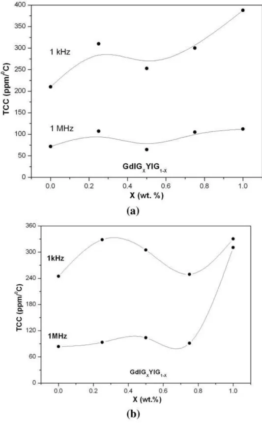
In Figures 5(a) and 5(b), we have the TCC as a function of the composite composition (GdIGXYIG1–X) to thick films and bulks, respectively. We can observe that the GdIG0.5YIG0.5 thick film
presented the lowest value (64.36 ppm/°C at 1 MHz) for the TCC. With the increase of the GdIG, there was an increase of the TCC value for all frequencies. The highest value was observed for the GdIG (387.68 ppm/°C at 1 kHz) thick film. Considering the use of ferrimagnetic devices in high-temperature environments, it is es-sential to know the thermal limit of the studied material and the
Figure 1 Geometry of circular microstrip antenna on an Al2O3substrate
dielectric properties as a function of the temperature. In general, TCC values for both thick films and bulk composites presented a similar behavior and could be used for electronic devices because of its short positive values.
In Table 3, one can observe the dielectric properties of GdIGXYIG1–Xcylindrical ferrite resonator measurement at micro-wave frequency. The values of resonant frequency (f0) were
at-tributed to TE011mode and calculated by considering the
trans-mission of the FRA, where we consideredrequals 1.rand tg␦E
values increased with the addition of GdIG in the composite because Gd has a higher density than the Y atom, that is, the density of GdIG structure is higher than that of YIG, as stated earlier.
The GdIG0.5YIG0.5composite was selected to study the
dielec-tric behavior at microwave frequencies and observed it as an antenna device. Figure 6 shows the experimental and simulated profile of the return loss (S11) for GdIG0.5YIG0.5microstrip
an-tenna, where these values were⫺16 and⫺20 dB at the resonance frequency (fr), respectively. The fr depends on r and r values
from insulator used to deposit the circle patch, see Eq. (1). In Table 4, the experimental and simulated values obtained from the nu-merical simulation are shown. The error offr and BW
(measure-ment in ⫺10 dB) was acceptable, and it was also possible to calculater, tg␦E, andrthrough simulation procedure.
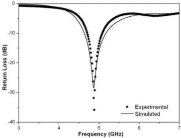
The experimental and simulated profile of the S11 for
TABLE 1 Thickness, Dielectric Permittivity (r), and Dielectric Loss (tg␦E) of the Thick-Film Composites at Room Temperature
X(%) (GdIGXYIG1–X)
Thickness (h) (m)
r tg␦E TCC (ppm/°C)
1 kHz 1 MHz 1 kHz 1 MHz 1 kHz 1 MHz
1.00 221.2 5.17 5.23 1.29⫻10⫺3 6.98⫻10⫺2 387.68 111.54
0.75 246.7 5.79 5.83 1.50⫻10⫺4 7.01⫻10⫺2 300.00 104.83
0.50 378.1 6.35 6.41 1.45⫻10⫺3 6.83⫻10⫺2 253.28 64.36
0.25 283.2 6.01 6.06 1.93⫻10⫺3 6.89⫻10⫺2 310.12 107.37
0.00 260.9 6.15 6.19 1.30⫻10⫺3 7.22⫻10⫺2 209.86 71.62
In addition, the temperature coefficients of capacitance (TCC) at 1 kHz and 1 MHz are also present.
TABLE 2 Thickness, Dielectric Permittivity (r), and Dielectric Loss (tg␦E) of the Bulk Composites at Room Temperature
X(%) (GdIGXYIG1–X)
Thickness (h) (m)
r tg␦E TCC (ppm/°C)
1 kHz 1 MHz 1 kHz 1 MHz 1 kHz 1 MHz
1.00 698.2 1671.95 1611.19 1.81⫻10⫺2 7.43⫻10⫺2 330.47 310.67
0.75 165.2 9.92 9.95 3.80⫻10⫺3 6.21⫻10⫺2 249.16 91.22
0.50 1703.3 10.93 10.87 9.35⫻10⫺3 6.23⫻10⫺2 305.01 103.68
0.25 1827.3 9.90 9.92 5.22⫻10⫺3 5.95⫻10⫺2 328.61 93.29
0.00 1901.5 9.01 8.99 8.86⫻10⫺3 5.79⫻10⫺2 244.56 83.43
In addition, the temperature coefficients of capacitance (TCC) at 1 kHz and 1 MHz are also present.
had an excellent convergence, with ⫺35 and ⫺28.43 dB for experimental and simulatedfrvalues, respectively. In Table 4, the
main differences between the microstrip and FRA antennas values can be observed. BW is quite distinct when considering the oper-ation of antennas. The microstrip antenna presented only 1.59% of BW, whereas FRA reached 7.61%. This difference could cause big changes in devices application; for instance, the FRA studied here can be used to develop wideband third-generation (3G) cellular phones whereas microstrip antenna cannot be used.
The values ofr, tg␦E, androf the GdIG0.5YIG0.5
ferrimag-netic composite (used as resonator in FRA and as substrate in microstrip antenna) were also calculated by the numerical simu-lation, where these results are presented in Table 4. The tg␦E
(⬃0.003) and r (0.9) values of the material did not change
because of the difference of the measurement frequency. However,
rof the GdIG0.5YIG0.5changed as a function of the frequency,
because 13.20, 10.98, and 9.43 at 8.185, 7.566, and 4.881 GHz, respectively, was obtained (see Tables 3 and 4). The first and third measurements were obtained through the antenna measurements
(see Table 4), whereas the second one through the Hakki–Coleman experiment (see Table 3). According to Balanis [1], the film used as substrates for the design of microstrip antennas must be thick, and their r values are usually moderate to promote a better efficiency, larger BW, and loosely bound fields for radiation into space. Both characteristics are present in GdIG0.5YIG0.5
ferrimag-netic composite used as substrate in the microstrip antenna studied in this work.
4. CONCLUSIONS
In this work, the dielectric properties of the GdIGXYIG1–Xferrite composite material at RF and microwave frequency were studied. These measurements were carried out in two different kinds of samples: thick films and cylindrical ceramic bulk ferrite resonator. For RF, we observed that the material is rather stable because of its short changes as a function of temperature and frequency range. The TCC values for all samples (thick films and cylindrical ce-ramic bulk samples) presented short positive values at the fre-quency ranged.
The GdIG0.5YIG0.5 thick film was used as a substrate for
microstrip antenna device, where the upper Ag electrode served as the circular patch antenna and a microstrip line was used as the feed line. It was possible to make the microstrip antenna operated in this configuration. Its operational frequency was⬃8.185 GHz. For comparing fr microstrip profile, another antenna experiment
was carried out with the same ferrite composite; however, in the bulk cylindrical geometry, it is operating as a FRA. Some differ-ences happened because of dielectric properties, dimensions of the material, and its microstructure. Ther, tg␦E, andrwere
calcu-lated by both the antenna experiments.
The GdIG0.5YIG0.5ferrite composite used as resonator in FRA
had characteristics that could be explored to develop wideband
TABLE 3 Microwave Measurements Obtained from Hakki–
Coleman Procedure; Thickness, Diameter (D), Dielectric resonant TE011(f0), Dielectric Permittivity (r), and Dielectric
Loss (tg␦E)
X(%) (GdIGXYIG1–X)
Thickness (h) (mm)
D (mm)
f0
(GHz) r tg␦E
1.00 7.608 15.559 7.135 14.473 0.012
0.75 7.737 15.937 7.539 12.439 0.004
0.50 8.414 16.262 7.566 10.987 0.003
0.25 9.044 16.551 7.624 9.795 0.002
0.00 9.414 16.572 7.688 9.189 0.001
Figure 6 Experimental and simulated return losses of GdIG0.5YIG0.5 FRA
TABLE 4 Antenna Resonant Frequency (fr), Bandwidth,r, tg␦E, androf the Microstrip Antenna (TM110mode) and Ferrite
Resonator Antenna (HE11␦mode) with Experimental (Exp.) and Simulated (Sim.) Values
Antenna
fr(GHz) Bandwidth (%)
r tg␦E r
Exp. Sim. Error (%) Exp. Sim. Error (%)
Microstrip 8.185 8.190 0.06 1.59 0.61 0.98 13.20 0.0030 0.9
Ferrite resonator 4.881 4.870 0.22 7.61 11.17 ⫺3.56 9.43 0.0035 0.9
The GdIG0.5YIG0.5ferrimagnetic composite was used as substrate in microstrip antenna and as resonator in FRA.
antenna of the third-generation (3G) cellular phones. However, the same material could also be used as a substrate for microstip antenna because of its thickness and moderatervalue.
ACKNOWLEDGMENTS
This work was supported, in part, by CAPES, CNPq, and FUN-CAP (Brazilian agencies), CELESTICA, and the U.S. Air Force Office of Scientific Research (AFOSR) (FA9550-08-1-0210).
REFERENCES
1. K.-M. Luk and K.-W. Leung, Dielectric ressonator antennas, Research Studies Press, Hertfordshire, England, 2003.
2. C.A. Balanis, Antenna theory: Analysis and design, 2nd ed., Wiley, New York, 1997.
3. D.M. Pozar, In: Proceedings of the IEEE, 1992, No. 1, Vol. 80, p. 79. 4. A. Keshtkar, A. Keshtkar, and A.R. Dastkhosh, Int J Antennas Propag
2008 (2008), 7; Article ID 389418.
5. A. Goldman, Magnetic ceramics (ferrites), In: ASM international— The materials information society. Engineered materials hand-book®—Ceramics and glasses, 1991, Vol. 4, pp. 1161–1165. 6. M. Barsoum, Fundamentals of ceramics, McGraw-Hill Companies,
Inc., New York, 1997.
7. R. Valenzuela, Magnetic ceramics, Cambridge University Press, , New York, 1994, p. 191.
8. F. Bertaut and F. Forrat, Comptes rendus de l’academie des sciences, Paris 242 (1956), 328.
9. S. Geller and M.A. Gilleo, J Phys Chemis Solids, 3 (1957), 30. 10. A.F.L. Almeida, P.B.A. Fechine, J.C. Go´es, M.A. Valente, M.A.R.
Miranda, and A.S.B. Sombra, Mater Sci Eng B 111 (2004), 113. 11. B.W. Hakki and P.D. Coleman, IRE Trans Microwave Theory Tech
MTT-8 (1960), 402– 410.
12. Y. Kobayashi and M. Katoh, IEEE Trans Microwave Theory Tech MTT-33 (1985), 586 –592.
13. R. Grabovickic, IEEE Trans Appl Supercond 9 (1999), 4607– 4612. 14. A.F.L. Almeida, R.R. Silva, H.H.B. Rocha, P.B.A. Fechine, F.S.A.
Cavalcanti, M.A. Valente, F.N.A. Freire, R.S. Moretzsohn, and A.S.B Sombra, Phys B: Condens Matter 403 (2008), 586.
15. R. Garg, P. Bhartia, I. Bahl, and A. Ittipiboon, Microstrip Antenna Design Handbook, Artech House, Norwood, MA 2001.
16. H. Mosallaaei and K. Sarabandi, IEEE Trans Antennas Propag 52 (2004), 1558.
17. P.B.A. Fechine, A. Tavora, L.C Kretly, A.F.L. Almeida, M.R.P. San-tos, F.N.A. Freire, and A.S.B. Sombra, IEEE J Electron Mater 35 (2006), 1848.
18. S.A. Long, M.W. Mcallister, and L.C. Shen, The resonant cylindrical dielectric cavity antenna, IEEE Trans Antennas Propag AP-31 (1983), 406 – 412.
19. D. Kajfez and P. Guillon, Dielectric resonators, The artech house microwave library, Norwood, MA 1986.
© 2009 Wiley Periodicals, Inc.
DESIGN OF MEANDER SQUARE-RING
RESONATOR AND ITS APPLICATION IN
RF POWER DIVIDER
Fei Zhang
Medical Center of Pittsburgh, 140 Morewood Ave, Pittsburgh, PA 15213; Corresponding author: [email protected]
Received 6 October 2008
ABSTRACT:First, this letter presents a novel meander square-ring resonator (MSRR) and its stop-band and slow-wave effects are investi-gated. Served by the proposed MSRR, unwanted higher-order 2nd and 3rd harmonics of power divider are effectively rejected benefiting from
its stop-band effect without any additional filter, and the physical length of quarter-wavelength 70.7 ohm microstrip in power divider is halved utilizing its slow-wave effect without decreasing the electrical length. Finally, power divider with area reduction by 42.6% is successfully ob-tained, compared with conventional design.© 2009 Wiley Periodicals, Inc. Microwave Opt Technol Lett 51: 1602–1604, 2009; Published on-line in Wiley InterScience (www.interscience.wiley.com). DOI 10.1002/ mop.24394
Key words:power divider; ring resonator; meander line
1. INTRODUCTION
Wilkinson power divider is widely used in modern RF and micro-wave systems and tremendous efforts are being made to miniatur-ize its sminiatur-ize such as meander line [1], three-dimensional (3-D) technologies [2], lumped-distributed techniques [3], electromag-netic band-gap (EBG) structures [4, 5], capacitive loading [6], and MEMS technology [7]. However, there still exists great challenge, in practice, to utilize these techniques to easily implement the power divider due to the existence of sharp corners [1], rigorous process requirements [2, 7], ground suspension [4, 5], or additional lumped elements [3, 6]. The power divider is generally designed based on the electrical length of a desired fundamental signal; however, high-order harmonic signals usually appear at the output port. This needs either additional harmonic tuning circuit parts or external low-pass filters to be inserted to suppress the unwanted harmonics. This will increase circuit size and insertion loss.
To solve above problems, following the concept of recent compact microstrip resonator cell (CMRC) technology in the form of perforations on microstrip itself [8, 9], this letter proposes a meander square-ring resonator (MSRR) to scale down power di-vider and reject the harmonics without degrading its performance.
2. DESIGN OF MSRR CELL
In this letter, all designs are on substrate with relative dielectric constantr⫽2.65 and thicknessh⫽1 mm at a 1.2 GHz center frequency. The layout of proposed MSRR is shown in Figure 1. Figure 2 gives the simulated S-parameters of proposed MSRR cell. It is worth noting that there exist deep stop-bands at around 2.4 GHz and 3.6 GHz, which correspond to the 2nd and 3rd harmonics of the center operating frequency, respectively. Thus, when the MSRR cells are introduced in the power divider, the two deep inherent stop-bands can suppress unwanted harmonic signals, without any additional filter. Furthermore, its slow-wave effect is demonstrated in Figure 3, which shows the S21 phase of the conventional microstrip and MSRR cell with the same physical length. It obviously indicates that the MSRR has the strong min-iaturization ability. This result is further quantitated in Figure 4 in terms of slow-wave factor (SWF)