The Analysis of the Microstructure and Mechanical Properties of Low Carbon Microalloyed
Steels after Ultra Fast Cooling
Yong Tiana, Hong-tao Wanga, Yong Lia*, Zhao-dong Wanga, Guo-dong Wanga
Received: August 31, 2016; Revised: March 10, 2017; Accepted: April 9, 2017
In this paper, two low carbon microalloyed steels, named as steel A and steel B, were fabricated by ultra fast cooling (UFC). In both steels, the microstructures containing quasi polygonal ferrite (QF), acicular ferrite (AF) and granular bainite (GB) can be obtained by UFC process. The amount of AF in steel B is more than that in steel A. The size and distribution of precipitates (Nb/Ti carbonitrides)
in steel B are iner and more dispersed than those of in steel A due to relatively low inish cooling temperature. The mechanical properties of both steels are efectively enhanced by UFC process. UFC process produces low-temperature transformation microstructures containing a signiicant amount of AF. The mechanical properties of steel B were more satisfactory than those of steel A due to the iner
average grain size, the greater amount of the volume fractions and smaller size of secondary phases.
Keywords: Low carbon microalloyed steels, Ultra fast cooling (UFC), Acicular ferrite (AF), The mechanical properties
* e-mail: [email protected]
1. Introduction
High-strength low-alloy (HSLA) steels are those high-strength structural steels having good toughness and weldability. This combination of properties have led to their varied applications in the automotive industry, in manufacturing of large diameter pipes for gas and oil transportation in the areas of low temperature, and in fabrication of plates for naval ship’s construction1. It is also popular to use HSLA
steels replacing the conventional low strength counterpart for reducing thicknesses and permitting the reduction of weight in weight-saving applications2. The wide range of
mechanical properties attainable in HSLA steels coupled with their relatively low cost are responsible for their high volume of production, which represents ~10% of the world’s steel production3. The evolution of HSLA steel
was based on low carbon content to improve weldability and suitable alloying elements were added to improve austenite hardenability4-6. Thermomechanical controlled
processing (TMCP) and microalloying in order to obtain desired microstructure and properties are the essence of ultra-low carbon microalloyed steel7. TMCP has become
the most powerful and efective manufacturing process
to satisfy increased hardenability, improved strength, and superior low-temperature toughness8. The microstructure,
which is related with the mechanical properties of the hot
rolled steels, is heavily inluenced by the cooling process
after hot rolling. The ultra fast cooling (UFC) technology was applied in order to get faster cooling rate. The cooling rate of UFC is more than twice that of traditional ACC (20ºC/s for 20mm)9. UFC process enhances strengthening
associated with precipitation and grain reinement10. The
microstructure and mechanical properties of low carbon
microalloyed steel can be signiicantly improved by UFC
process after hot deformation11.
This article presents an analysis of the inal microstructure
of two low carbon microalloyed steels after UFC process. Tensile and Charpy impact tests at room temperature and lower temperature were performed, respectively, to evaluate strength and toughness. The key objective of this study was to discuss and determine the strengthening contribution of the morphologies of ferrite, bainite and the detected Nb/Ti (C, N) carbonitrides in the two experimental steels subjected to UFC process.
2. Experimental Procedure
Two types of low-alloyed, low-carbon steels were produced
in terms of diferent content of Cr, Mo and Ni. Plates with
thickness of 250 mm were used for rolling mill tests. The cylindrical rod specimens with 8 mm diameter and 15 mm length were machined from the plates in order to measure the transformation temperature in a thermomechanical simulator. The austenite nonrecrystallization temperature (Tnr) was evaluated through softening fraction-interpass time curves. Itwas calculated by the back extrapolation method12.The
Ar3 and Ar1, which denote the start and inish temperatures of the austenite-to-ferrite transformation, respectively, were measured using the thermomechanical simulator. A schematic illustration of the double-pass compression test to measure Ar3 and Ar1 is shown in Figure 1. In Figure 1, specimens were heated at a rate of 50ºC/s, solution treated at 1150ºC for 180 s, deformed to 30% compressive strain at
1s-1, cooled to 920ºC at 5ºC/s, deformed to 40% compressive
strain at 1s-1. Then, the specimens were cooled at 30ºC/s to
room temperature. The chemical compositions and measured transformation temperature (Tnr, Ar3 and Ar1) of the steels are listed in Table 1.
Figure 1. Schematic illustration of measuring Ar3 and Ar1.
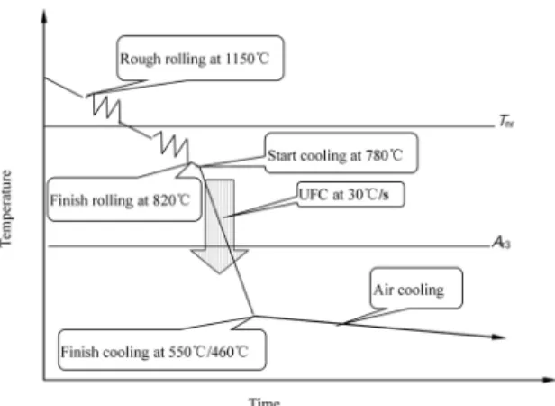
After being hold for 280 min at a soaking temperature of 1200ºC, the rough-rolling temperature started at 1150ºC above the nonrecrystallization temperature of austenite for
both steels. The inish-rolling stage was started at 920ºC and inished rolling at 820ºC. The rolled plates were air-cooled to
the start cooling temperature of 780ºC, were water-cooled to 550ºC and 460ºC at a cooling rate of 30ºC/s, and then were air-cooled for steel A and B, respectively. The processing schedule of the experimental steels is shown in Figure 2.
As a result, the inal plates with thickness of 17.5 mm and
19.3 mm for steel A and B, respectively, were obtained. Five tensile and Charpy impact specimens were collected from various positions along the center-line of the plates,
respectively. The lat tensile specimens, 160 mm in total length, 20 mm in efective width, 17.5/19.3 mm in thickness and 50
mm in gauge length, were machined from the plates with the longitudinal axis parallel to the longitudinal direction, and tensile tests were carried out on an INSTRON 4206 machine at a strain rate of 5 mm min-1. The Charpy impact specimens
direction were also paralleled to the rolling direction. The tensile specimens were tested at room temperature, and impact tests of steels A and B were performed at -10ºC and -15ºC, respectively, according to Chinese standard to obtain an averaged result13. The Vickers hardness tester was
used to measure the Vickers hardness with 10-kg load. The microstructures of the transverse section of the specimens were examined with an optical microscopy (OM) after a LePera etching14 and with a scanning electron microscopy
(SEM) after conventional 4% Nital etching. Thin specimens were observed in a transmission electron microscopy (TEM) with energy dispersive spectrometry (EDS) facility. Volume
Table 1. Chemical composition (wt %) and measured transformation temperature (ºC) of both steels.
Steel C Si Mn P S Nb Cr Ni Cu Mo Ti B Tnr Ar3 Ar1
A 0.086 0.170 1.590 0.012 0.005 0.074 0.020 0.010 0.020 0.002 0.013 0.0003 950 590 480
B 0.054 0.220 1.710 0.004 0.001 0.072 0.241 0.202 0.012 0.129 0.012 0.0002 975 600 490
Figure 2. The processing schedule of the experimental steels.
fractions of phases present in the plates were measured by an image analyzer.
3. Experimental Results
3.1. Tensile and charpy impact properties
Yield strength (Rt0.5), ultimate tensile strength (Rm), yield ratio (Rt0.5/Rm), total elongation (A50), the Charpy absorbed energy (AK) and Vickers hardness (HV10) of the specimens after UFC process are summarized in Table 2. Apparently, steel B has higher values than steel A. The Charpy absorbed energies of steel A at -10ºC are higher than 436J, and those of steel B at -15ºC are higher than 396J. The hardness values of steel B are also higher than those of steel A.
Average ultimate tensile and yield strength, yield ratio, total elongation and the Charpy absorbed energy of both steels are shown in Figure 3. In Figure 3, steel B has higher average value of strengths than that of steel A. Furthermore, the Charpy absorbed energies level of steel B at -15ºC is only slightly lower than those of steel A at -10ºC, despite microalloying and UFC process result in higher strength and higher hardness for the former.
3.2. Microstructures
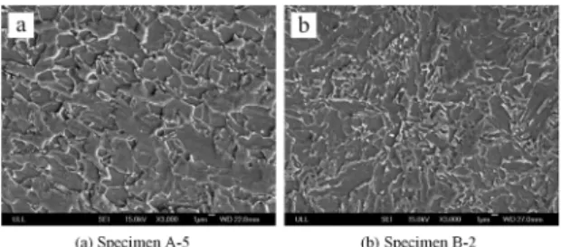
OM and SEM micrographs of both steels are shown in Figure 4and Figure 5. In Figure 4, ferrite appears gray, bainite appears dark, and both martensite and retained austenite
appear white since they are diicult to be tinted in LePera
etchant14. By visual inspection, all specimens are mostly
island-shaped martensite-austenite (MA) constituents. QF and AF ferrite coexist in the microstructure. The QF grains have irregular and jagged boundaries, containing subboundaries. The AF is an acicular microstructure formed inside austenite grains and contains MA at irregularly shaped grain boundaries. Steel A is mostly composed of QF together with a very small amount of pearlite (P). Steel B mostly consists of AF, together with GB, instead of P.
The volume fractions of secondary phases were evaluated and the results are shown in Table 3. Secondary phases are mainly retained austenite and martensite-austenite constituents, and cementite can be ignored for low carbon content (0.086% maximum). The volume fraction of MA tends to be higher in steel B than that in steel A. A large number of M-A islands
in steel B are ine and dispersed (Figure 5, Table 3).
SEM micrographs of the fracture surface of the Charpy impact specimens fractured at -10ºC for specimen A-5 and at Table 2. Mechanical properties of the experimental steels.
Specimen No. Rt0.5/MPa Rm/MPa Rt0.5/ Rm A50/% AK/J HV10
Steel A
A-1 555 615 0.9 41 436 at -10ºC 219
A-2 530 615 0.86 40 408 at -10ºC 218
A-3 535 600 0.89 44 288 at -10ºC 207
A-4 515 600 0.86 40 345 at -10ºC 205
A-5 530 620 0.85 41 385 at -10ºC 220
Steel B
B-1 590 675 0.87 35 394 at -15ºC 232
B-2 530 685 0.77 32 371 at -15ºC 249
B-3 535 680 0.79 34 361 at -15ºC 238
B-4 570 680 0.84 37 396 at -15ºC 243
B-5 540 680 0.79 38 331 at -15ºC 242
Figure 3. Average properties of both steels.
Figure 4. Optical micrographs of specimens after UFC process.
Figure 5. SEM micrographs of specimens after UFC process.
-15ºC for specimen B-2, are shown in Figure 6. In Figure 6, a lot of dimples were found. The fracture appearance of steel B still exhibits toughness characteristics even the fracture occurs at low temperature.
The TEM of specimens reveals the presence of quasi polygonal ferrite (QF) and acicular ferrite (AF), martensite-austenite (MA) island, dislocation and carbide precipitation at the bainitic ferrite platelet (Figures 7, 8, 9, 10 and 11). Specimen A-5 exhibits a mixture of QF and AF microstructure as shown in Figure7 (a). Large amounts of AFs are found in specimen B-2 as shown in Figure7 (b). The presence of islands of MA component within QF and/or AF structure is
further conirmed by the TEM studies (Fig. 8). In Figure8 (b), ine AFs are largely observed, while MA is homogeneously
reveals that the particle is enriched with Nb, Ti, C and N. The results denote the presence of carbonitrides precipitates of niobium and titanium, Nb/Ti (C, N).
Table 3. Average grain size and the size and the volume fractions of secondary phases.
Steel
Quasi polygonal
ferrite
Acicular ferrite
Granular bainite/%
Average grain
size/μm The volume fractions of secondary phases/%
The size of secondary
phases/μm
Average size of secondary
phases/μm
A Bal. - - 10.34 ± 2.3 12.67 ± 0.4 4.32~5.94 5.18 ± 0.1
B - Bal. - 9.47 ± 2.6 17.73 ± 0.5 3.54~5.12 4.36 ± 0.3
Figure 6. Fractographs of Charpy impact specimens fractured at -10ºC and -15ºC.
Figure 7. TEM micrographs of specimens showing the formation of quasi polygonal ferrite (QF) and acicular ferrite (AF).
Figure 8. TEM micrographs of specimens showing the presence of MA island.
4. Discussion
Two low-carbon steel alloyed with Si, Mn, Cr and Mo and microalloyed with Nb, Ti and Ni have been designed. The low carbon is preferred for the current steel from the viewpoint of low segregation, good toughness, and superior
Figure 9. TEM micrographs of dislocations in ferrite observed in specimens.
Figure 10. TEM micrograph of specimen A-5 showing the presence of carbonitrides precipitates.
Figure 11. TEM micrograph of specimen B-2 showing the presence of carbonitrides precipitates.
weldability. The addition of Si, Mn, Cr, Mo and other alloying elements increase the hardenability of austenite. Austenite
has been stabilized up to a very low temperature, and γ→α
transformation has been retarded. Cr, Mo and Ni have been added at a balanced level in steel B, which improves austenite hardenability. Mo retards separation of ferrite from parent austenite and depresses Bstemperature. The amount of GB in steel B is higher than that in steel A (Fig. 5). This is attributed to the presence of Mo in steel B.
this high soaking temperature, austenite grain growth would
be restricted by ine Nb/Ti (C, N) particles. A controlled
precipitation process of carbides, nitrides and carbo-nitrides
formed during the TMCP is responsible for the ine-grained ferritic structure. The inish-rolling temperature is lower than
the nonrecrystallization temperature (Table 1) of austenite present in the steel and therefore static recrystallization of austenite is ruled out. The pancaked grains are formed due to rolling in the nonrecrystallized austenite region. Dynamic recrystallization is likely to occur as strain accumulation takes place from one roll pass to another in the absence of static recrystallization4. The rolling at γ nonrecrystallization
region accumulates a strain (i.e., dislocations) in austenite
grains and this strain can promote the ferrite grain reinement by acting as a nucleation site for γ-α transformation15. The
average ferrite grain size relates to thickness of pancaked austenite grain, alloying elements that depress austenite to ferrite transformation and ultra fast cooling (UFC) from
austenite region. The grain reinement efect is suiciently
achieved by the controlled rolling process at high temperatures, and low-temperature transformation microstructures are formed by the accelerated cooling process16. UFC process
is favorable to the formation of ferrite nuclei and results in
the ine ferrite grains (Fig. 4, 5 and Table 3).
In general, with increased cooling rate the nature and morphology of ferrite alters from polygonal to plate-type or elongated and subsequently to lath and acicular type ferrite17. UFC process promotes the formation of acicular
ferrite (Fig. 7). According to Lu et al.18, a combination of
high cooling rate and low coiling temperature/interrupted cooling temperature in microalloyed steels helps to produce
a ine bainitic/acicular ferrite microstructure, making higher
strength steels possible. It is worth noting that it is easy for a rolling mill to produce steel products under relative higher temperature rolling because the load is not heavy during
rolling. Therefore, the enhancement of the inishing rolling
temperature (820ºC) of the present steel is favorable for practice mill. On the other hand, a considerable amount of AFs in the high start cooling temperature (780ºC) condition is formed. It has been well accepted that the AF, in the GB
microstructure, comes from a mixed difusion and shear
transformation mode during continuous cooling beginning at a temperature above the upper bainite transformation region temperature19. The AF nucleates at intragranular sites and it
is characterized by an assemblage of interwoven non-parallel ferrite laths with high density of tangled dislocations, where the most parts of the neighboring lath (subgrain) boundaries have dissimilar orientations19. A microstructure of acicular
ferrite has the potential of combining high strength and high toughness, because a crack would have to follow a more tortuous path through a microstructure of acicular ferrite20.
As mentioned above, the structure of steel A presents a smaller amount of acicular ferrite than steel B. The enhanced mechanical properties are related to that the microstructures
are composed mainly of low-temperature transformation microstructures (AF) in steel B (Table 2, Fig. 3).
It was already mentioned that GB is an equiaxed microstructure, and contains island-type MA constituents. It is well known that MA is mainly generated at rapid cooling
rates and low inish cooling temperatures16. The volumetric
fraction of M-A islands increases because of higher cooling rates20. The size of MA tended to decrease with increasing
inish cooling temperature. As hard secondary phases such as
MA are readily transformed at low temperatures21, therefore,
both steels show high strength due to UFC process, except for the action of Mo in the steel22. This is also the reason for
that the strengths of steel B were higher than those of steel A because of the strengthening contribution due to the MA constituent (Fig. 8).
As mentioned previously, QF and/or AF contain a high dislocation density (Fig. 9). This is because UFC process would help to keep more dislocations introduced by deformation. The strength is mainly decided by the barriers to movement of dislocation line and deviate from M-A islands10. Therefore,
high strength levels were obtained for both steels, and steel B ontaining a higher volume fraction and greater dispersion of MA showed higher yield and tensile strengths.
The ine particle precipitation directly comes from
UFC process after hot deformation for both steels. When several of the microalloyed elements are present in the alloy, the precipitated carbides or carbonitrides have a
complex composition of Ti, Nb and V being more efective
as strengthener in the steel19,22. The suppression of grain
boundary migration due to microalloying is caused by either
the solute dragging efect caused by segregation of alloying elements to the boundaries, or the pinning efect caused by carbo-nitride precipitates. These very ine precipitates are responsible for the ine-grained ferritic structure23. Noting that
the size and distribution of precipitates (Nb/Ti carbonitrides)
in steel B are iner and more dispersed than those of in steel
A (Fig. 10, 11). Despite the precipitates reduced the absorbed
energy by facilitating a ductile fracture, the ine precipitation of the diferent carbides or carbonitrides (TiCN, NbCN)
during the hot-rolling provides an additional precipitation
strengthening in the inal steel plate.
There is some solid solution strengthening from the addition of alloying elements intwo low carbon steels. UFC process also results in the dislocation strengthening. Moreover, the improvement of mechanical properties also
results mainly from the reinement of ferrite grain size and
precipitation strengthening. When the cooling rate increases, the grain size decreases overall, and the volume fraction of bainitic ferrite increases, which leads to the higher strength and the lower ductility and toughness16. The ine particle
precipitation contributes to the strengthening of the steel19.
However, the Charpy absorbed energies of steel B do not
and lowers the ductile brittle transition temperature in the steels. On the other hand, Charpy impact absorbed energy is proportional to the volume fraction of acicular ferrite16.
Microstructures with a signiicant proportion of acicular
ferrite (AF) have an optimized combination of mechanical properties in both steels after UFC process. This is in
rather good agreement to the other authors’ indings20. As
mentioned above, the size of secondary phases decreases with
decreasing inish rolling temperature (Fig. 5, Table 3). The yield strength is reduced when the inish cooling temperature
decreases further below a certain temperature, as suggested by Sung16. As a result, steel B exhibits high strengths, as
well as relatively low yield ratio. Satisfactory mechanical properties can be obtained by UFC process for two low carbon microalloyed steels.
5. Conclusions
(1) The microstructures containing QF, AF and GB in low carbon microalloyed steels can be obtained mainly by UFC process. The amount of AF in steel B is more than that in steel A. The size and distribution of precipitates (Nb/
Ti carbonitrides) in steel B are iner and more dispersed than those of in steel A due to relatively low inish cooling
temperature.
(2) The mechanical properties of both steels are
efectively enhanced by UFC process. This is attributed
to the strengthening contribution caused by solid solution,
grain reinement, dispersion, dislocation and precipitation
strengthening. The mechanical properties of steel B are more
satisfactory than those of steel A due to the iner average
grain size, the greater amount of the volume fractions and the smaller size of secondary phases.
(3) UFC process produces low-temperature transformation
microstructures containing a signiicant amount of AFs.
Crack propagation would have to follow a more tortuous path through a microstructure of acicular ferrite. Therefore, an optimized combination of mechanical properties can be obtained in both steels. This is also a reason for that the mechanical properties of steel B were higher than those of steel A.
6. Acknowledgment
This work was subsidized by the Natural Science Foundation of China (Grant No.51234002) and the national key research and development program(Grant No. 2016YFB0300701 &
2016YFB0300605). The authors are also grateful to the staf
of Qinhuangdao Shouqin Metal Materials Co, Ltd.
7. References
1. Khaki DM, Ayaz M, Arab NBM, Noroozi A. Multiresponse Optimization of Mechanical Properties and Formability of Hot
Rolled Microalloyed Steels. Journal of Materials Engineering and Performance. 2013;23(3):1002-1015.
2. Misra RDK, Nathani H, Hartmann JE, Siciliano F. Microstructural evolution in a new 770 MPa hot rolled Nb-Ti microalloyed steel. Materials Science and Engineering: A. 2005;394(1-2):339-352.
3. Pereloma EV, Kostryzhev AG, AlShahrani A, Zhu C, Cairney JM,
Killmore CR, et al. Efect of austenite deformation temperature
on Nb clustering and precipitation in microalloyed steel. Scripta Materialia. 2014;75:74-77.
4. Shukla R, Das RK, Ravi Kumar B, Ghosh SK, Kundu S, Chatterjee S. An Ultra-low Carbon, Thermomechanically Controlled Processed Microalloyed Steel: Microstructure and Mechanical Properties. Metallurgical and Materials Transactions A. 2012;43(12):4835-4845.
5. Kim J, Jung JG, Kim DH, Lee YK. The kinetics of Nb(C,N) precipitation during the isothermal austenite to ferrite transformation in a low-carbon Nb-microalloyed steel. Acta Materialia. 2013;61(19):7437-7443.
6. Khalaj G, Nazari A, Livary AK. Application of ANFIS for modeling of microhardness of high strength low alloy (HSLA) steels in continuous cooling. Materials Research. 2013;16(4):721-730.
7. Xie H, Du LX, Hu J, Misra RDK. Microstructure and mechanical properties of a novel 1000 MPa grade TMCP low carbon microalloyed steel with combination of high strength and excellent toughness. Materials Science and Engineering: A. 2014;612:123-130.
8. Bandyopadhyay PS, Ghosh SK, Kundu S, Chatterjee S. Evolution of Microstructure and Mechanical Properties of Thermomechanically Processed Ultrahigh-Strength Steel. Metallurgical and Materials Transactions A. 2011;42(9):2742-2752.
9. Tian Y, Tang S, Wang BX, Wang ZD, Wang GD. Development and industrial application of ultra-fast cooling technology.
Science China Technological Sciences. 2012;55(6):1566-1571.
10. Tang S, Liu Z, Wang G, Misra RDK. Microstructural evolution and mechanical properties of high strength microalloyed steels: Ultra Fast Cooling (UFC) versus Accelerated Cooling (ACC).
Materials Science and Engineering: A. 2013;580:257-265.
11. Ravikumar SV, Jha JM, Mohapatra SS, Pal SK, Chakraborty
S. Inluence of Ultrafast Cooling on Microstructure and
Mechanical Properties of Steel. Steel Research International. 2013;84(11):1157-1170.
12. Laasraoui A, Jonas JJ. Recrystallization of austenite after deformation at high temperatures and strain rates - Analysis and modeling. Metallurgical Transactions A. 1991;22(1):151-160.
13. National Standard of the People’s Republic of China. Petroleum and Natural Gas Industries-Steel Pipe for Pipeline Transportation Systems. GB/T 9711-2011. Beijing: Chinese Standard Press; 2011. p. 27.
15. Kim YW, Song SW, Seo SJ, Hong SG, Lee CS. Development of Ti and Mo micro-alloyed hot-rolled high strength sheet steel by controlling thermomechanical controlled processing schedule.
Materials Science and Engineering: A. 2013;565:430-438.
16. Sung HK, Lee S, Shin SY. Efects of Start and Finish Cooling
Temperatures on Microstructure and Mechanical Properties of Low-Carbon High-Strength and Low-Yield Ratio Bainitic Steels.
Metallurgical and Materials Transactions A. 2014;45(4):2004-2013.
17. Zuo X, Zhou Z. Study of Pipeline Steels with Acicular Ferrite Microstructure and Ferrite-bainite Dual-phase Microstructure.
Materials Research. 2015;18(1):36-41.
18. Lu J, Omotoso O, Wiskel JB, Ivey DG, Henein H. Strengthening Mechanisms and Their Relative Contributions to the Yield Strength of Microalloyed Steels. Metallurgical and Materials Transactions A. 2012;43(9):3043-3061.
19. Morales EV, Silva RA, Bott IS, Paciornik S. Strengthening mechanisms in a pipeline microalloyed steel with a complex microstructure. Materials Science and Engineering: A. 2013;585:253-260.
20. Pedrosa IRV, Castro RS, Yadava YP, Ferreira RAS. Study of phase transformations in API 5L X80 Steel in order to increase its fracture toughness. Materials Research. 2013;16(2):489-496.
21. Sung HK, Shin SY, Hwang B, Lee CG, Lee S. Efects of Cooling Conditions on Microstructure, Tensile Properties, and Charpy Impact Toughness of Low-Carbon High-Strength Bainitic Steels. Metallurgical and Materials Transactions A. 2013;44(1):294-302.
22. Park DB, Huh MY, Shim JH, Suh JY, Lee KH, Jung WS. Strengthening mechanism of hot rolled Ti and Nb microalloyed HSLA steels containing Mo and W with various coiling temperature.
Materials Science and Engineering: A. 2013;560:528-534.
23. Gallego J, Rodrigues AR, Assis CLF, Montanari L. Second