Chapter 8
!
Design Concepts
!
Slide Set to accompany
Software Engineering: A Practitioner
ʼ
s Approach, 7/e
#
by Roger S. Pressman
Slides copyright © 1996, 2001, 2005, 2009
by Roger S. Pressman
For non-profit educational use only
May be reproduced ONLY for student use at the university level when used in conjunction
with
Software Engineering: A Practitioner's Approach, 7/e.
Any other reproduction or use is
prohibited without the express written permission of the author.
Design
!
Mitch Kapor, the creator of Lotus 1-2-3,
presented a “software design manifesto” in
Dr.
Dobbs Journal.
He said:
!
Good software design should exhibit:
!
Firmness:
A program should not have any bugs that
inhibit its function.
!
Commodity:
A program should be suitable for the
purposes for which it was intended.
!
Delight:
The experience of using the program should
Analysis Model -> Design Model
!
Analysis Model
use-cases - text use-case diagrams activity diagrams swim lane diagrams
data flow diagrams control-flow diagrams processing narratives
f l ow- or i e n te d e l e me n ts
be h a v i or a l e l e me n ts c l a ss- ba se d
e l e me n ts sc e n a r i o- ba se d
e l e me n ts
class diagrams analysis packages CRC models collaboration diagrams state diagrams sequence diagrams
Da t a / Cla ss Design Arc hit ec t ura l Design
Int erfa c e Design
Com ponent -Lev el Design
Design and Quality
!
the design must implement all of the explicit
requirements
contained in the analysis model,
and it must accommodate all of the implicit
requirements desired by the customer.
!
the design must be a readable, understandable
guide
for those who generate code and for
those who test and subsequently support the
software.
!
the design should provide a complete picture of
the software
, addressing the data, functional,
and behavioral domains from an
Quality Guidelines
!
A design should exhibit an architecture that (1) has been created using
recognizable architectural styles or patterns, (2) is composed of components
that exhibit good design characteristics and (3) can be implemented in an
evolutionary fashion
!
For smaller systems, design can sometimes be developed linearly.
!
A design should be modular; that is, the software should be logically partitioned
into elements or subsystems
!
A design should contain distinct representations of data, architecture,
interfaces, and components.
!
A design should lead to data structures that are appropriate for the classes to
be implemented and are drawn from recognizable data patterns.
!
A design should lead to components that exhibit independent functional
characteristics.
!
A design should lead to interfaces that reduce the complexity of connections
between components and with the external environment.
!
A design should be derived using a repeatable method that is driven by
information obtained during software requirements analysis.
!
Design Principles
!
The design process should not suffer from
ʻ
tunnel vision.
ʼ
!
The design should be traceable to the analysis model.
!
The design should not reinvent the wheel.
!
The design should “minimize the intellectual distance” [DAV95] between
the software and the problem as it exists in the real world.
!
The design should exhibit uniformity and integration.
!
The design should be structured to accommodate change.
!
The design should be structured to degrade gently, even when aberrant
data, events, or operating conditions are encountered.
!
Design is not coding, coding is not design.
!
The design should be assessed for quality as it is being created, not after
the fact.
!
The design should be reviewed to minimize conceptual (semantic) errors.
!
Fundamental Concepts
!
Abstraction
—data, procedure, control
!
Architecture
—the overall structure of the software
!
Patterns
—”conveys the essence” of a proven design solution
!
Separation of c
oncerns
—any complex problem can be more easily
handled if it is subdivided into pieces
Modularity
—compartmentalization of data and function
!
Hiding
—controlled interfaces
!
Functional independence
—single-minded function and low coupling
!
Refinement
—elaboration of detail for all abstractions
!
Aspects
—a mechanism for understanding how global requirements
affect design
!
Refactoring
—a reorganization technique that simplifies the design
!
OO design concepts
—Appendix II
!
Design Classes
—provide design detail that will enable analysis
Data Abstraction
!
Procedural Abstraction
!
implemented with a "knowledge" of the
!
Separation of Concerns
!
Any complex problem can be more easily
handled if it is subdivided into pieces that can
each be solved and/or optimized
independently
!
A
concern
is a feature or behavior that is
specified as part of the requirements model for
the software
!
By separating concerns into smaller, and
Modularity
!
"modularity is the single attribute of software that allows
a program to be intellectually manageable" [Mye78].
!
Monolithic software (i.e., a large program composed of a
single module) cannot be easily grasped by a software
engineer.
!
The number of control paths, span of reference, number of
variables, and overall complexity would make
understanding close to impossible.
!
In almost all instances, you should break the design into
many modules, hoping to make understanding easier
and as a consequence, reduce the cost required to build
Why Information Hiding?
!
reduces the likelihood of “side effects”
!
limits the global impact of local design
decisions
!
emphasizes communication through
controlled interfaces
!
discourages the use of global data
!
leads to encapsulation—an attribute of
high quality design
!
Stepwise Refinement
!
open
!
walk to door;
!
reach for knob;
!
open door;
!
walk through;
!
close door.
!
repeat until door opens
!
turn knob clockwise;
!
if knob doesn't turn, then
!
take key out;
!
find correct key;
!
insert in lock;
!
endif
!
pull/push door
!
move out of way;
!
Sizing Modules: Two Views
!
MODULE
What's
Functional Independence
!
Functional independence is achieved by developing
modules with "single-minded" function and an
"aversion" to excessive interaction with other modules.
!
Cohesion
is an indication of the relative functional
strength of a module.
!
A cohesive module performs a single task, requiring little
interaction with other components in other parts of a
program. Stated simply, a cohesive module should (ideally)
do just one thing.
!
Coupling
is an indication of the relative interdependence
among modules.
!
Coupling depends on the interface complexity between
Aspects
!
Consider two requirements,
A
and
B.
Requirement
A crosscuts
requirement
B
“if a
software decomposition [refinement] has been
chosen in which
B
cannot be satisfied without
taking
A
into account. [Ros04]
!
An
aspect
is a representation of a cross-cutting
Aspects—An Example
!
Consider two requirements for the
SafeHomeAssured.com
WebApp.
Requirement A is described via the use-case
Access camera
surveillance via the Internet.
A design refinement would focus on
those modules that would enable a registered user to access video from
cameras placed throughout a space. Requirement B is a generic
security requirement that states that a registered user must be validated
prior to using
SafeHomeAssured.com.
This requirement is applicable
for all functions that are available to registered SafeHome users. As
design refinement occurs, A* is a design representation for requirement
A and B* is a design representation for requirement B. Therefore, A*
and B* are representations of concerns, and B* cross-cuts A*.
!
An aspect is a representation of a cross-cutting concern. Therefore, the
Refactoring
!
Fowler [FOW99] defines refactoring in the following manner:
!
"Refactoring is the process of changing a software system in
such a way that it does not alter the external behavior of the
code [design] yet improves its internal structure.”
!
When software is refactored, the existing design is examined
for
!
redundancy
!
unused design elements
!
inefficient or unnecessary algorithms
!
poorly constructed or inappropriate data structures
!
or any other design failure that can be corrected to yield a better
OO Design Concepts
!
Design classes
!
Entity classes
!
Boundary classes
!
Controller classes
!
Inheritance
—all responsibilities of a superclass is
immediately inherited by all subclasses
!
Messages
—stimulate some behavior to occur in the
receiving object
!
Polymorphism
—a characteristic that greatly reduces the
Design Classes
Analysis classes are refined during design to become
entity
classes
!
Boundary classes
are developed during design to create the
interface (e.g., interactive screen or printed reports) that the user
sees and interacts with as the software is used.
!
Boundary classes are designed with the responsibility of managing
the way entity objects are represented to users.
!
Controller classe
s
are designed to manage
!
the creation or update of entity objects;
!
the instantiation of boundary objects as they obtain information from
entity objects;
!
complex communication between sets of objects;
!
validation of data communicated between objects or between the
The Design Model
architecture elements interface elements component-level elements deployment-level elements low high class diagrams analysis packages CRC models collaboration diagramsuse-cases - text use-case diagrams activity diagrams swim lane diagrams
collaboration diagrams data flow diagrams control-flow diagrams processing narratives data flow diagrams
control-flow diagrams processing narratives state diagrams sequence diagrams state diagrams sequence diagrams
design class realizations subsystems
collaboration diagrams
design class realizations subsystems collaboration diagrams refinements to: deployment diagrams class diagrams analysis packages CRC models collaboration diagrams component diagrams design classes activity diagrams sequence diagrams refinements to: component diagrams design classes activity diagrams sequence diagrams
design class realizations subsystems collaboration diagrams component diagrams design classes activity diagrams sequence diagrams
a na ly sis model
Design Model Elements
!
Data elements
!
Data model --> data structures
!
Data model --> database architecture
!
Architectural elements
!
Application domain
!
Analysis classes, their relationships, collaborations and behaviors are
transformed into design realizations
!
Patterns and “styles” (Chapters 9 and 12)
!
Interface elements
!
the user interface (UI)
!
external interfaces to other systems, devices, networks or other
producers or consumers of information
!
internal interfaces between various design components
.
!
Component elements
!
Architectural Elements
!
The architectural model [Sha96] is derived
from three sources:
!
information about the application domain
for the
software to be built;
!
specific requirements model elements
such as data
flow diagrams or analysis classes, their relationships
and collaborations for the problem at hand, and
!
the availability of architectural patterns
(Chapter 12)
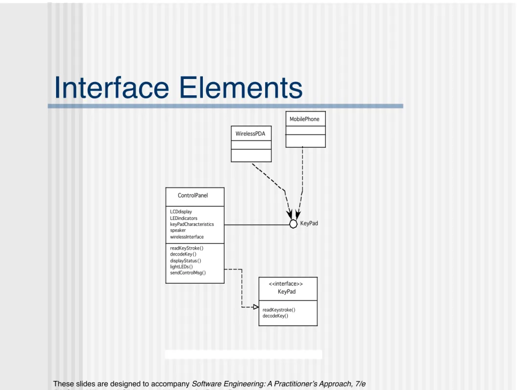
Interface Elements
!
ControlPanel LCDdisplay LEDindicators keyPadCharacteristics speaker wirelessInterface readKeyStroke() decodeKey() displayStatus () lightLEDs() sendControlMsg()Figure 9.6 UML interface representation for Cont rolPa nel
Component Elements
!
SensorManagement
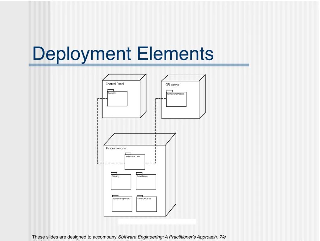
Deployment Elements
!
Figure 9.8 UML deployment diagram for SafeHome
Personal computer
Security
homeManagement
Surveillance
communication
Control Panel CPI server
Security homeownerAccess