Tribology
in
Industry
www.tribology.fink.rsNumerical
Modeling
of
Disc
Brake
System
in
Frictional
Contact
A. Belhocine
a, A.R. Abu Bakar
b, M. Bouchetara
aa DepartmentofMechanicalEngineering,USTOOranUniversity,L.P1505El ‐ Mnaouer,USTO31000Oran,Algeria
bDepartmentofAutomotiveEngineering,UniversitiTeknologiMalaysia,81310UTMSkudai,Malaysia.
Keywords:
Brakedisc
Heatflux
Heattransfercoefficient
Thermalanalysis
Finiteelement
Stress
A B S T R A C T
Safetyaspectinautomotiveengineeringhasbeenconsideredasanumber
onepriorityindevelopmentofnewvehicle. Eachsinglesystemhasbeen
studied and developed in order to meet safety requirement. Instead of
having air bag, good suspension systems, good handling and safe
cornering,thereisonemostcriticalsysteminthevehiclewhichisbrake
systems. The objective of this work is to investigate and analyse the
temperature distribution of rotor disc during braking operation using
ANSYSMultiphysics.Theworkusesthefiniteelementanalysistechniques
to predictthe temperaturedistributiononthefullandventilatedbrake
disc and to identify the critical temperature of the rotor by holding
account certain parameters such as; the material used, the geometric
designofthediscandthemodeofbraking.Theanalysisalsogivesus,the
heatfluxdistributionforthetwodiscs.
© Published by Faculty of Engineering
Corresponding author:
AliBelhocine
Faculty of Mechancal Engineering,
USTOOranUniversity,
L.P.1505El‐Mnaouer,USTO,
31000OranAlgeria
E‐mail:[email protected]
1. INTRODUCTION
Braking system is one of the important safety components of a vehicle. Braking system is mainly used to decelerate vehicles from an initial speed to a given speed. Friction based braking systems are the common device to convert kinetic energy into thermal energy through friction between the brake pads and the rotor faces. (igh temperatures can also lead to overheating of brake fluid, seals and other components. The stopping capability of brake increases by the rate at which heat is dissipated due to forced convection and the thermal capacity of the system [ ]. Tracing of thermal
effects in any given part of the brake is possible by numerical simulations, but it requires a valid model to be constructed. The verification of such model can be performed on the basis of real temperature measurements, using the image sequences recorded by a thermal camera. The analysis of recorded temperature distribution may help to identify the worn out brake components [ ].
Brake disc convective cooling has been historically studied by means of experimental and theoretical methods [ , ] and the optimization were only boosted with the advent of modern computational resources in the late
eighties [ ]. Currently, although of not simple usage and requiring previous understanding of the basics of fluid mechanics and heat transfer coupled with knowledge of flows numerical modeling, CFD has significantly gained preference in the automotive industry design process as tool for predicting complex flow and heat transfer behaviour in regions where otherwise very laborious and time consuming by a combination of node‐to‐surface and surface‐to‐ surface contact elements [ ].
Gao and Lin [ ] stated that there was considerable evidence to show that the contact temperature is an integral factor reflecting the specific power friction influence of combined effect of load, speed, friction coefficient, and the thermo physical and durability properties of the materials of a frictional couple. Experiments showed that the friction coefficient in general decreased with increasing sliding speed and applied load, but increased with increasing disc temperature up to °C and then decreased above this temperature. The specific wear rate was found to increase with increasing sliding speed and disc temperature [ ].
Nouby et al [ ] introduced a nontraditional evaluation tool to examine the effects of different materials, in practical applications, that are used in fabricating disc brake components for commonly used or special requirements such as heavy‐duty performance and racing cars. An extension of the FE models discussed earlier is an experimental set up work would be needed. As result, brake disc convective cooling analysis and optimization is nowadays mostly carried out using CFD commercial codes, e,g. [ ].
Many investigations of analysis of heat flow through the ventilated disc brakes are reported in the literature. Michael and Roland [ ] discussed the airflow patterns in the disc rotors. Wallis et al [ ] carried out a numerical study using Fluent on disc rotor blades to examine the effects of local heat and mass transfer of the axial gap distances for a single and co‐rotating disc. The study of single rotating disc showed that heat and mass transfer coefficient are enhanced considerably by decreasing the hub height. )n the sliding contact process, a temperature variation in the contacting bodies that resulted from frictional heating will cause many related engineering problems, such as
wear, fusion, and deformation. Since Blok [ ] and Jaeger and Carslaw [ ] pioneered the studies of temperature rise at the contact surfaces due to moving heat surfaces, there are more researches aimed at studying the temperature rise and distribution. Vick and Furey [ ] deduced the base theory of the frictional heat and calculated a set of regularly
arranged contact areas temperature
on friction and wear effects, with potential failures caused by high thermal levels and thermo mechanical stresses. )t is well known that the temperature sensitivity of friction materials is a critical aspect wishing to ensure their smooth and reliable functioning. )n fact, it influences the thermo‐elastic instabilities, which in turn alter the friction performance at the braking junctions [ ]. )n the front wheel, for example, disc brake pads absorb a major amount up to % of the total kinetic energy of an automobile. This causes the generation of high temperature up to °C on the disc. The severity of such temperature rise is further manifested in the form of a very high flash temperature up to °C at the contacting asperities [ ]. At such high temperatures, pads suffer from a loss of effectiveness called fade because of a reduction in the kinetic friction coefficient. (igh interfacial temperatures can lead to a decrease in shear strength of the pad and consequently a decrease in frictional force which induces fade [ ]. Thus, correlating the friction coefficient to the operating temperature level for the coupled friction surfaces is probably the most critical point in designing safe and effective braking systems and it is not surprising that many researchers pay their attention to theoretical models for surface temperature evaluation as well as to surface temperature measurements. A lot of studies about heat transfer at the coupled interfaces are reported in literature which takes into account the superposition of several phenomena, each described by a number of simplifying assumptions: experimental, analytical and numerical methods are attempted to understand and to predict wear effects. From an experimental standpoint, the system relative motion, its geometry and the high thermal gradients which are typically attained make experimental temperature detection a complex matter if one wishes to use thermocouples located directly at the friction interface [ ‐ ].
Therefore, non‐contact measurements
including optical or infrared methods could be the solution and early works are appearing in this sense [ ‐ ]. The latter technique seems to be the most effective and valuable due to its ability to perform continuous temperature map recording with relatively high resolutions when compared to other traditional methods but it is to consider that the area to focus on is hidden by the coupled surfaces. Due to the described
difficulties in the experimental approach, in recent years, the finite element method [ ] has become the preferred method for studying the problem at hand while few analytical models are also available [ ]. (owever, a critical analysis of the above mentioned works allows to clearly concluding that, often, numerical predictions for temperature distribution aren t adequately validated by experimental tests. Spulber and Voloaca [ ] proposed a new simulation method of a disc brake thermal stress resistance, for different temperatures, by interactive processing
of images obtained by thermography.
Temperature evaluation for different working regimes can be made by recording and processing thermograms of a disc brake heated inside the laboratory by an external heating source. Taken pictures along the temperature variation, from the ambient value to a value close to real one obtained on the usual experiments, are processed using image analyse softwares.
)n the work of Mosleh et al. [ ] a brake dust generated in vehicle brakes causes discoloration of wheels and, more importantly, the emission of particles suspected of health hazard in the environment. Laboratory testing of brake pad materials against cast iron discs revealed that the majority of wear particles are submicrometer in size. Wear particles with a size of nm had the highest percentage in the particle size distribution plots, regardless of the magnitude of the nominal contact pressure and the sliding speed. The precise calculation for each of the rate of wear [ ‐ ] and the internal energy of friction clutch will lead to Knowledge the lifetime of friction material with high accuracy. Due to their predominantly submicrometer size, a significant amount of brake dust particles may be inhalable in environmental and occupational exposure situations.
temperature with important gradients called hot spots . The formation of such localized hot spots is accompanied by high local stresses that can lead to material degradation and eventual failure [ ]. Also, the hot spots can be a source of undesirable frictional vibrations, known in the automotive disc brake community as hot roughness or hot judder [ ].
The ventilated disc is lighter than the solid disc, and additional convective heat transfer occurs on the surface of the vent hall. Thus, the ventilated disc can control its temperature rise and minimize the effects of thermal problems such as the variation of the pad friction coefficient, brake fade and vapor lock [ , ].
The ventilated disc, however, may increase judder problems by inducing an uneven temperature field around the disc. Also, the thermal capacity of the ventilated disc is less than that of the solid disc, and the temperature of the ventilated disc can rise relatively faster than that of the solid disc during repetitive braking [ ]. Therefore, thermal capacity and thermal deformation should be carefully considered when modifying the shape of the ventilated disc. Recently, Abdullah and Schlattmann [ ] carried out detailed of temperature distribution for dry friction system flywheel, clutch disc and pressure plate during repeated engagements. The finite element method used to compute the temperature field for clutch disc under different pressure
distributions. Two types of pressure
distributions were applied between contact surfaces uniform pressure and the linear pressure with disc radius maximum at inner radius and minimum at outer radius based on theory of clutch design. The effect of convection is considered in both cases. The same authors [ ] applied the finite element method to calculate the heat generated on the surfaces of friction clutch and temperature distribution for case of bands contact between flywheel and clutch disc, and between the clutch disc and pressure plate one bad central and two bands and compared with case of full contact between surfaces for single engagement and repeated engagements. Furthermore, their work shows effect of pressure capacity on the temperature field, when the pressure is a function of time , three kinds of pressure variation with time
constant , linear and parabolic are presented.
)n this study, we will make a modeling of the thermal behaviour of the dry contact between the discs of brake pads at the time of braking phase; the strategy of calculation is based on the software ANSYS . This last is comprehensive mainly for the resolution of the complex physical problems. As a current study of this problem ANSYS Simulations with less assumption and less program restrictions have been performed for the thermo mechanical case. Temperature distribution obtained by the transient thermal analysis is used in the calculations of the stresses on disc surface.
2. NUMERICALPROCEDURE
)n braking process, the temperature field changes input heat flux and heat exchange conditions. The input heat flux is mainly relevant to friction coefficient disc, the angular velocity of brake disc while heat exchange is connected with the friction pair materials and external environmental factors.
Based on the first law of Thermodynamics, during braking, kinetic energy is converted to thermal energy. Due to friction between the main components of disc brake pads and disc the conversion of energy takes place.
)nitially the generated thermal energy is transferred by conduction to the components in contact and next by convection to environment. The initial heat flux qo into the rotor face is directly
calculated using the following formula [ ]:
0
1
2
2
o
d p
m g V z
q
A
Where z=a/g is the braking effectiveness, a is the deceleration of the vehicle [m/s ], ɸ is the rate distribution of the braking forces between the front and rear axle, Ad disc surface swept by a
brake pad [m ],Vo is the initial speed of the vehicle
[m/s], εp is the factor load distribution on the disc surface, m is themass of the vehicle [kg] and g is
the acceleration of gravity . [m/s ].
Fig.1.Geometrical characteristics of the ventilated disc.
The loading corresponds to the heat flux on the disc surface. The dimensions and the parameters used in the thermal calculation are recapitulated in Table .
Table1. )nput parameters.
Description Values
)nner disc diameter, mm Outer disc diameter, mm Disc thickness T( , mm Disc height ( , mm Vehicle mass m, kg )nitial speed Vo, km/h
Deceleration a, m/s
Effective rotor radius Rrotor, mm .
Rate distribution of the braking forces ɸ,%
Tire radius Rtire, mm
Factor of charge distribution of the disc εp .
Surface disc swept by the pad Ad, mm
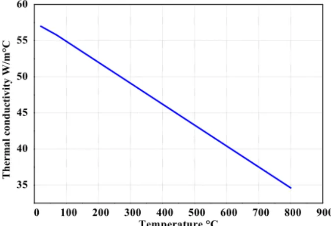
The material of brake disc is gray cast iron GF with high carbon content, with good thermophysical characteristics, thermoelastic characteristics of which adopted in this simulation of the rotor are recapitulated in Table .
Table2.Material properties of brake disc. Material Properties Disc Thermal conductivity, k W/m °C
Density, ρ kg/m Specific heat,C J/Kg °C
Poisson s ratio, v . Thermal expansion, ‐ /K .
Elastic modulus, E GPa
Rotors are made of cast iron for three reasons [ ]:
)t is relatively hard and resists wear. )t is cheaper than steel or aluminum.
)t absorbs and dissipates heat well to
cool the brakes.
)t is very difficult to exactly model the brake disc, in which there are still researches are going on to find out transient thermal behaviour of disc brake during braking applications. There is always a need of some assumptions to model any complex geometry. These assumptions are made, keeping in mind the difficulties involved in the theoretical calculation and the importance of the parameters that are taken and those which are ignored. )n modeling, we always ignore the things that are of less importance and have little impact on the analysis. The assumptions are always made depending upon the details and accuracy required in modeling.
Due to the application of brakes on the car Disc brake rotor, heat generation takes place due to friction and this thermal flux has to be conducted and dispersed across the Disc Rotor cross section. The condition of braking is very much severe and thus the thermal analysis has to be carried out. The thermal loading as well as structure is axis‐symmetric. (ence axis‐ symmetric analysis can be performed, but in this study we performed ‐D analysis, which is an exact representation for this thermal analysis. Thermal analysis is carried out and with the above load structural analysis is also performed for analysing the stability of the structure.
TH H
Clampholes Coolingfin
To simplify the analysis, several assumptions have also been made as follows [ ]
All kinetic energy at disc brake rotor surface
is converted into frictional heat or heat flux. )n other words, a high amount of kinetic energy is converted into heat energy at interfaces according to the first law of thermodynamics during the slipping period and the heat generated between contact surfaces will be dissipated by conduction between friction clutch components and by convection to the environment.
The heat transfer involved for this analysis
only conduction and convection process. This heat transfer radiation can be neglected in this analysis because of small amount which is % to % [ ]. )ndeed, the heat radiation only plays an important role at high temperature and low speeds.
The disc material is considered as
homogeneous and isotropic, because Young s modulus, Poisson s ratio, and the thermal expansion coefficient are assumed to be constant for isotropic.
The domain is considered as axis‐
symmetric. The temperature field is symmetry with respect to the central plane of the brake disc
)nertia and body force effects are negligible during the analysis. (ere, a transient analysis calculates the effects of thermal loading on a structure, while ignoring inertia and damping effects.
The disc is stress free before the application of
brake. Due to the application of brakes of the rotor, heat generation takes place due to friction and this temperature so generated has to be conducted across the disc across section.
)n this analysis, the ambient temperature and
initial temperature has been set to °C.
All other possible disc brake loads are
neglected, for example, the effects of wear or other atmospheric factors.
Only certain parts of disc brake rotor will
apply with convection heat transfer such as cooling vanes area, outer ring diameter area and disc brake surface on which, each surface of the rotor was subjected to different values of convection heat transfer coefficient obtained from this calculations.
Uniform pressure distribution by the brake
pad onto the disc brake surface. Uniform pressure distribution in the contact region is often valid when the pad is new.
The thermal conductivity and specific heat are a function of temperature, Figs. and .
0 100 200 300 400 500 600 700 800 900 35
40 45 50 55 60
The
rma
l c
o
nduc
tiv
ity
W/m
°C
Temperature °C
Fig.2. Thermal conductivity versus temperature.
0 100 200 300 400 500 600 700
450 500 550 600 650 700 750 800
Sp
ec
if
ic he
a
t
J
/kg
°C
Tem perature °C
Fig.3. Specific heat versus temperature.
3. FINITE ELEMENT FORMULATION FOR
HEATCONDUCTION
The unsteady heat conduction equation of each body for an axis‐Symmetric problem described in the cylindrical coordinate system is given as follows:
1
r z
T
T
T
c
rk
k
t
r r
r
z
z
With the boundary conditions and initial condition:
*
0
T
T on
q
n
h T
(
T
)
on
1*
2
n n
q
q on
T
T at time
0
0
where ρ, c, kr and kz are the density, specific heat and thermal conductivities in r and z direction of the material, respectively. Also, T* is the
prescribed temperature, h the heat transfer coefficient, qn* the heat flux at each contact interface due to friction, T∞ the ambient temperature, T the initial temperature and Γ, Γ
and Γ are the boundaries on which temperature, convection and heat flux are imposed, respectively.
Using Galerkin s approach, a finite element formulation of unsteady heat Eq. can be written in the following matrix form as:
C T
T
KH T
T
R
Where CT is the capacity matrix, KHT is the
conductivity matrix. T and R and are the nodal
temperature and heat source vector, respectively.
The most commonly used method for solving Eq. is the direct integration method based on the assumption that temperature Tt at time t and temperature Tt+Δt at time t+Δt have the following relation:
T
tt
T
t
1
T
t
T
tt
t
Eq. can be used to reduce the ordinary differential Eq. to the following implicit algebraic equation:
1
2
2 1
T T t t T T t
t t t
C
b KH
T
C
b KH
T
b R
b R
Where the variable b1 and b2 are given by:
b
1
t b
,
2
1
t
For different values of the well‐known numerical integration scheme can be obtained [ ] in this study, . . was used, which
is an unconditionally stable scheme.
4. PREPARATION OF THE GEOMETRY AND
THEMESH
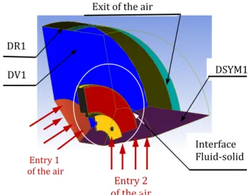
4.1Fluidfield
Considering symmetry in the disc, one took only the quarter of the geometry of the fluid field Fig.
by using software ANSYS )CEM CFD.
Fig.4.
.
Fig.4.Definition of surfaces of the fluid field.
4.2PreparationoftheMesh
This stage consists in preparing the mesh of the fluid field. )n our case, one used a linear
tetrahedral element with nodes and
elements Fig. .
Fig.5.Mesh of the fluid field.
At the time of the braking process, a part of the frictional heat escapes into the ambient air by convection and radiation. Consequently, the determination of the heat transfer coefficients is essential. Their exact calculation is, however, rather difficult, because these coefficients depend on the location and the construction of the braking system, the speed of the vehicle and consequently, on the air circulation. Since the process of heat transfer by radiation is not too significant, we will determine using ANSYS CFX . code only the convection coefficient h of
the disc. This parameter will be exploited to determine the three‐dimensional distribution of the temperature of the disc.
)nterface Fluid‐solid Exit of the air
DSYM DR
DV
Entry of the air
For reasons of symmetry of the disc, one took only the quarter of the geometry in the case of the full and ventilated disc; one kept the tetrahedral form to generate the mesh of the discs Figs. and .
Fig.6. Meshing of the full disc Number of elements
.
Fig. 7. Meshing of the ventilated disc Number of
elements .
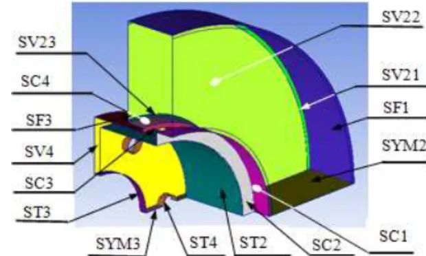
4.3ModelinginANSYSCFX
For the preparation of the mesh of CFD model, one defines initially, various surfaces of the disc in integrated computer engineering and manufacturing )CEM CFD as shown in Fig. ; we used a linear tetrahedral element with
nodes and elements. )n order not to
weigh down calculation, an irregular mesh is used in which the mesh is broader where the gradients are weaker nonuniform mesh ,
Fig.8. Definition of surfaces of the full disc. Table.3Boundary conditions.
Boundary Boundary condition Parameters
)nlet Pressure inlet Atmospheric pressure and temperature
Outlet Pressure outlet Atmospheric pressure and temperature Domain
edges Symmetry Symmetry
Disc surface Wall thermal properties of K temperature, grey cast iron
a Physical model
)n this step, one declares all of the physical characteristics of the fluid and the solid. After the meshing, are defined all the parameters of the different models to be able to start the analysis.
b Definition of the domains
)nitially, one valid the elaborated models and one activate in the option "Thermal Energy» the calculation of heat transfer «(eat Transfer ". Fluid domain: Speed entry: Vent non.st = Vent – Va.t Disc domain: Entering flux: FLUXnon.st = CF Vent
non.st ,
CF = . Vent non.st = Vent – Va.t
FLOWnon.st: Non stationary flux entering.
Vent non.st: Non stationary speed entering of the air.
c Definition of materials
We introduce into the computer code the physical properties of used materials. )n this study, we selected one cast iron material FG
.
The boundary conditions concerning the pads will be also defined. One selects the options Wall and "Symmetry ", because there will be the possibility of adjusting a certain number of parameters in the boundary conditions such as flux entering the disc.
e Application of the interfaces domains The areas of interfaces are commonly used to create the connection or linkage areas. Surfaces located between the interactions regions air‐ disc are reported as solid‐fluid interface.
f Temporary Condition
Since in this study is to determine the temperature field in a disc brake during the braking phase of a vehicle of average class, we take the following temporal conditions:
‐ Braking time= . [s] ‐ )ncrement time = . [s] ‐ )nitial time = [s]
Before starting the calculation and the analysis with ANSYS CFX PRE, it can be ensured that the model does not contain any error.
The airflow through and around the brake disc was analyzed using the ANSYS CFX software package. The ANSYS‐CFX solver automatically calculates heat transfer coefficient at the wall boundary. Afterwards the heat transfer coefficients considering convection were calculated and organized in such a way, that they could be used as a boundary condition in thermal analysis. Averaged heat transfer coefficient had to be calculated for all disc using ANSYS CFX Post as it is indicated in Fig. .
Fig. 9. Distribution of heat transfer coefficient on a full disc in the steady state case FG .
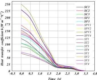
g Results of the calculation of the heat transfer coefficient h
The heat transfer coefficient is a parameter related to velocity of air and the shape of brake disc, and many other factors. )n different velocity of air, the heat transfer coefficient in different parts of brake disc changes with time [ ]. (eat transfer coefficient will depend on air flow in the region of brake rotor and vehicle speed, but it does not depend on material. )n this simulation, it is determined the average value of the coefficient h Wall heat Transfer Coefficient , variable with time Figs. and .
-0,5 0,0 0,5 1,0 1,5 2,0 2,5 3,0 3,5 4,0
0 10 20 30 40 50 60 70 80 90 100 110 120 SC1 SC2 SC3 SC4 SF1 SF3 ST2 ST3 ST4 SV1 SV2 SV3 SV4 He at t ran sf er c o e ffi c ie n t h [Wm -2 °C -1 ] Time [s]
Fig. 10. Variation of heat transfer coefficient h of various surfaces for a full disc in transient case FG .
-0,5 0,0 0,5 1,0 1,5 2,0 2,5 3,0 3,5 4,0
0 25 50 75 100 125 150 175 200 225 250 SC1 SC2 SC3 SF1 SF3 SPV1 SPV2 SPV3 SPV4 ST1 ST2 ST3 ST4 SV1 SV2 SV3 SV4 Heat tra n sf er c o e ff icien
t h [
W
m
-2 °C -1 ]
Tim e [s]
Fig. 11. Variation of heat transfer coefficient h of various surfaces for a ventilated disc in transient case
FG .
4.4Determinationofthedisctemperature
The characteristics of the vehicle and of the disc brake are listed in Table .
The vehicle speed decreases linearly with time until the value as shown in Fig. . The variation of the heat flux during the simulation time is represented on the Fig. .
0 1 0 2 0 3 0 4 0
0 1 0 2 0 3 0
S
p
eed [m
s
-1 ]
T im e [s]
S p e e d [m s-1
]
Fig.12. Speed of braking versus time Braking of type .
0 1 0 2 0 3 0 4 0
0 1 x1 06
2 x1 06
3 x1 06
4 x1 06
5 x1 06
He
a
t F
lux [
W
m
-2 ]
T im e [s]
H e a t F lu x
Fig.13. (eat Flux versus time.
4.5Creatingoffiniteelementmeshfordisc
Meshing of the full and ventilated disc has been done using ANSYS Multiphysics. The element used of the meshing is of tetrahedral shape Figs. and .
Fig. 14. Full type disc mesh model total number of nodes – total number of elements .
Fig.15. Ventilated type disc mesh model total number of nodes ‐ total number of elements
.
4.6Applyingtheboundaryconditions
The boundary conditions are introduced into module ANSYS Workbench [Multiphysics], by choosing the mode of first simulation of the all permanent or transitory , and by defining the physical properties of materials. These conditions constitute the initial conditions of our simulation. After having fixed these parameters, one introduces a boundary condition associated with each surface.
Total time of simulation = s )ncrement of initial time = . s
)ncrement of minimal initial time = . s )ncrement of maximal initial time = . s )nitial temperature of the disc = °C Materials: Grey Cast )ron FG .
Convection: One introduces the values of the heat transfer coefficient (h) obtained
for each surface in the shape of a curve Figs. ,
Flux: One introduces the values obtained by flux entering by means of the code CFX.
5. RESULTSANDDISCUSSIONS
A model presents a three dimensional solid Disc squeezed by two finite‐width friction material called pads. The entire surface, S, of the Disc has three different regions including S and S . On S heat flux is specified due to the frictional heating between the pads and Disc, and S is defined for the convection boundary. The rest of the region, except S U S , is either temperature specified or assumed to be calculated: the inner and outer rim area of Disc. Since the axis‐ symmetric model is considered all the nodes on the hub radius are fixed. So the nodal displacements in the hub become zero, i.e. in radial, axial and angular directions.
5.1Influenceofconstructionofthedisc
Figure shows the variation of the
temperature versus time during the total time simulation of braking for a fall disc and a ventilated disc. The highest temperatures are reached at the contact surface of disc‐pads. The strong rise in temperature is due to the short duration of the braking phase and to the speed of the physical phenomenon. For the two types of discs, one disc has an immediate, fast temperature rise followed by a fall in temperature after a certain time of braking.
0 2 4 6 8 1 0
2 2 5 2 5 0 2 7 5 3 0 0 3 2 5 3 5 0 3 7 5 4 0 0
Temp
er
a
tu
re [°
C]
T im e [ s ]
V e n t i l a t e d d i s c F u l l d i s c
a b
Fig. 16. Temperature distribution of a full a and ventilated disc b of cast iron FG .
)t can be concluded that the geometric design of the disc is an essential factor in the improvement of the cooling process of the discs.
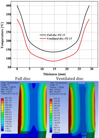
Figures and respectively show the
temperature variation according to the thickness and radius. )t can be noted that there is an appreciable variation of temperature between the two types of full and ventilated disc. The influence of ventilation on the temperature field appears clearly at the end of the braking t = . s .
0 5 10 15 20 25 30
50 100 150 200 250 300 350 400
T
em
p
er
a
ture [°C]
Thickness [mm]
Full disc FG 15 Ventilated disc FG 15
Full disc Ventilated disc
Fig.17. Temperature variation through the thickness for both designs with same material FG .
70 80 90 100 110 120 130 140
150 200 250 300 350 400
Full disc FG 15 Ventilated disc FG 15
Temperatur
e [°C
]
Radius [m m ]
5.2Influenceofbrakingmode
The disc brake and the wheel are dimensioned according to the performance and economic requirements of the vehicle. They must support increasingly greater mechanical and thermal loads at mean velocities in permanent progression. Among the parameters having an influence on the thermal behaviour of the disc brake is the braking mode, which depends on the driver and the traffic conditions. Certain modes of braking can involve the destruction of the disc and consequently, cause serious traffic accidents. A braking mode is represented in the form of braking cycles, which describe the variation of vehicle speed versus time v= f t .
During vehicle operating, the braking system is subjected to repeated actions of the driver. )n this study, we considered two types of braking whose total simulation time is estimated to be equal to s. This is intended to determine the saturation temperature disc under a cyclic thermal load. This cycle is repeated several times: the first mode consists of braking and acceleration, and the second consists of braking, cooling and deceleration.
Figure shows a driving cycle of fourteen successive braking, in the form of sawtooth.
0 20 40 60 80 100 120
0 5 10 15 20 25 30
Sp
eed [
m
s
-1 ]
Time [s]
Fig.19. Driving cycle with fourteen repeated braking Mode .
Figure shows another mode of braking
where after each phase of braking one has an idle.
0 2 0 4 0 6 0 8 0 1 0 0 1 2 0
0 5 1 0 1 5 2 0 2 5 3 0
V
ite
ss
e [m
s
-1 ]
T im e [ s]
Fig.20. Cycle braking with phase of idles after each braking mode .
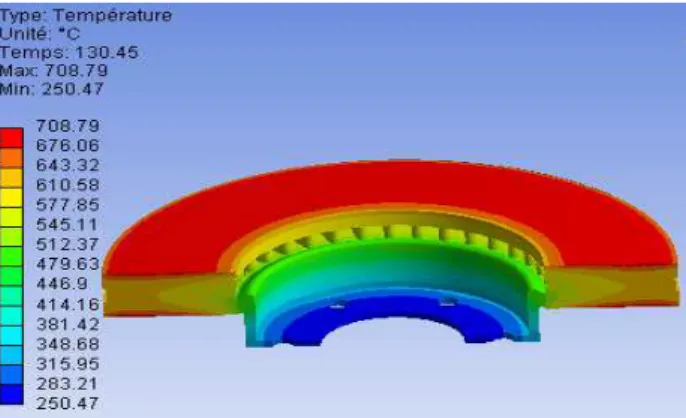
Figures and show the three‐dimensional distribution of the maximum temperature reached in the disc for the two modes of braking, one observes a normal increase in temperature in the tracks of friction and the external crown. The vanes very strongly warm up and tend to dilate and become deformed until the complete solidification of the disc. This deformation will cause the setting in umbrella of the disc.
Fig. 21. Temperature map of the disc in mode of braking at the moment t= . [s].
Figure shows the comparison of the change in temperature of the disc for a cyclic braking process between the first mode and the second mode. For two contours, it can be noted that the temperatures in the disc rise greatly with each application of the brake, then begin the exponential decline. The more the number of repetitions of braking increases, the more the maximum temperatures increase. The initial state of the disc changes after each cycle; the downtimes allow only one partial cooling. After each cooling phase, the disc begins to warm again. )n fact, during successive braking s the capacity of cooling of the disc is insufficient to lower the surface temperature to near the initial temperature, which causes an accumulation of energy and therefore a higher surface temperature. These results show, that the transient thermal behaviour of a disc brake depends on the braking cycle imposed and it is dominating because it dictates the cooling time of the disc. According to Fig. , it can be noted that in the case of braking cycle mode , a reduction of the temperature of approximately °C is . % compared with the first cycle. We conclude that the braking mode with a cooling phase influences the heat transfers in the disc very positively, which involves a reduction in the maximum temperature of the interface, which causes cracking and mechanical wear.
0 20 40 60 80 100 120
0 100 200 300 400 500 600 700 800 900 1000 1100 1200
Te
mp
er
at
ure
[°
C]
Tim e [s] M ode of braking 2 M ode of braking 1
Fig. 23. Temperature variation of the two braking modes versus time.
)n addition, this tendency will enable us to ensure the safety and fatigue life of the brake system component. Finally, it would be interesting to carry out this calculation on brake test benches in order to validate these results of the numerical simulation.
5.3Comparisonbetweenfullandventilateddisc
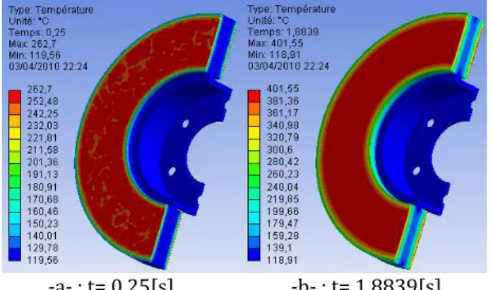
)n this part, we presented the cartographies of total and directional heat flux and as well as the temperature distribution in a full and ventilated disc and of cast iron FG for each moment with braking. The temperature distribution of the disc at the beginning braking with t= . s is inhomogeneous. According to experimental tests' carried out by research , braking often begin with the formation from hot circles relatively on the uniform surfaces of the disc in the circumferential direction, moving radially on the disc and transforming then into hot points
hotspot .The appearance of the phenomenon
of the hot points is due to the nonuniform dissipation of heat flux.
Concerning the heat flux, it can be noted according to Figs. and that the maximum value of the total heat flux is located on the level of the calorific throat at the end of braking t = . s ; this is explained by the increase in the gradients and the thermal concentrations in this zone. The calorific throat is manufactured so as to limit the heat flux coming from the friction tracks and moving towards the bowl of the disc brake in order to avoid the excessive heating of the rim and the tire. During the heating, the disc is tightened to dilate in the hot zones from where creating of compressive stresses with plasticization. On the other hand, during cooling, there is appearance of residual stresses of traction. The disc is thus subjected during its rotation to constraints traction/compression.
a. Fulldisc
‐c‐ : t= . [s] ‐d‐ : t= [s]
‐e‐ : t= [s] ‐f‐ : t= [s] Fig. 24. Temperature distribution for a full disc of material FG .
‐a‐ : t= . [s] ‐b‐ : t= . [s]
‐c‐ : t= . [s] ‐d‐ : t= [s]
‐e‐ : t= [s] ‐f‐ : t= [s] Fig.25. Distribution of total heat flux for a full disc of material FG .
‐a‐ : According to the axis X
‐b‐:According to the axis Y
‐c‐ :According to the axis Z
Fig. 26. Distribution of directional heat flux at the moment t= . [s] according to three axes X, Y, Z for a full disc of a material FG .
b. Ventilateddisc
‐c‐ : t= . [s] ‐d‐ : t= [s]
‐e‐ : t= [s] ‐f‐ : t= [s]
Fig. 27. Temperature distribution for a ventilated disc of material FG .
‐a‐ : t= . [s] ‐b‐ : t= . [s]
‐c‐ : t= . [s] ‐d‐ : t= [s]
‐e‐ : t= [s] ‐f‐ : t= [s]
Fig.28. Distribution of total heat flux for a ventilated disc of material FG .
‐a‐ : According to the axis X
‐b‐ : According to the axis Y
‐c‐ : According to the axis Z
Fig. 29. Distribution of directional heat flux at the moment t= . [s] according to three axes X, Y, Z for a ventilated disc of a material FG .
5. CONCLUSION
)n this study, we have presented a numerical simulation of the thermal behaviour of a full and ventilated disc in transient state. By means of the computer code ANSYS we were able to study the thermal behaviour of a gray cast iron
FG .
thermal behaviour of the disc brake. Through the numerical simulation, it could be noted that the quality of the results concerning the temperature field is influenced by several parameters such as:
• Technological parameters illustrated by the
design.
• Numerical parameters represented by the
number of elements and the step of time.
• Physical parameters expressed by the types
of materials.
• Braking mode implemented.
Regarding the calculation results, it can be say that they are satisfactorily in agreement with those commonly found in the literature investigations. )t would be interesting to solve the problem in thermo mechanical disc brakes with an experimental study to validate the numerical results, for example, on test benches, in order to demonstrate a good agreement between the model and reality.
Regarding the outlook, there are three recommendations for the expansion of future work related to disc brake that can be done to further understand the effects of thermo mechanical contact between the disc and pads, the recommendations are as follows:
1. Experimental study to verify the accuracy of
the numerical model developed.
2. Tribological and vibratory study of the
contact disc – pads;
3. Study of dry contact sliding under the
macroscopic aspect macroscopic state of the surfaces of the disc and pads .
REFERENCES
[ ] R. Thundil Karuppa Raj, R. Ramsai, J. Mathew, G. Soniya: Numericalinvestigationoffluidflowand
heattransfercharacteristicsontheaerodynamics
ofventilateddiscbrakerotorusingCFD, Thermal
Science, )ssue , pp. ‐ , .
[ ] M. Kastek, T. Piatkowski, (. Polakowski, J. Małachowski, K. Damaziak: Thermographics
measurementsandnumericalsimulationofacar
breaks, in: 11th International Conference on
QuantitativeInfraRedThermography, ‐ June
2012, Naples, )taly, )D‐ , pp. ‐ .
[ ] R. Limpert: The thermal performance of
automotive disc brakes, SAE paper, Doi:
. / , .
[ ] S. Morgan and R.W. Dennis: A theoretical
prediction of disc brake temperatures and a
comparison with experimental data, SAE
Technical Papers, No. , .
[ ] M.N. Dhaubhadel: Review:CFDapplicationsinthe
automotive industry, Journal of Fluids
Engineering, Vol. , No. , pp. ‐ , . [ ] J. Abdo: Experimental Technique to Study
Tangential to Normal Contact Load Ratio,
Tribology Transactions, Vol. , No. , pp. ‐ , .
[ ] C.(. Gao, X.Z. Lin: Transient temperature field
analysis of a brake in a non‐axisymmetric
threedimensional model, J. Materials Processing
Technology, Vol. , No. ‐ , pp. ‐ , . [ ] B. Özt“rk, F. Arslan,S. Özt“rk : EffectsofDifferent
Kinds of Fibers on Mechanical and Tribological
Properties of Brake Friction Materials,
Tribology Transactions, Vol. , No. , pp. ‐ , .
[ ] M. Nouby, J. Abdo, D. Mathivanan, K. Srinivasan:
Evaluation of Disc Brake Materials for Squeal
Reduction, Tribology Transactions, Vol. , No. ,
pp. ‐ , .
[ ] E. Palmer, J. Fieldhouse, R. Mishra: Optimisation
of pinshape andits configuration fora pintype
vente brake disc using CFD., F)S)TA, Yokohama,
Japan, .
[ ] D.(. Michael, L.R. Roland: VentilatedBrakeRotor
Air Flow Investigation, SAE, Doi:
. / , .
[ ] L. Wallis, E. Leonardi, B. Milton: Air Flow and
Heat Transfer in Ventilated Disc Brake Rotors
with Diamond and Tear‐Drop Pillars, in :
Proceedings of International Symposium on
Advances in Computational Heat Transfer,
Australia, Vol. , pp. ‐ , .
[ ] (. Blok: Theoreticalstudyoftemperatureriseat
surfaces of actual contact under oiliness
lubricating conditions, in: Proceedings of the
Institute of Mechanical Engineers General
Discussion on Lubrication and Lubricants,
London, UK,Vol. , pp. – , .
[ ] J.C. Jaeger, (.S. Carslaw: Conduction of Heat in
Solids, Clarendon Press, Oxford, UK, .
[ ] B. Vick, M.J. Furey: Abasictheoreticalstudyofthe
temperature riseinslidingcontact withmultiple
contacts, Tribology )nternational, Vol. , No. ,
[ ] (. Chen, W. (u, (. Wang, W. Wang: Calculation
oftemperaturefieldsofbodiesinslidingcontact
without lubrication, Journal of Tsinghua
University Science and Technology , Vol. , No.
, pp. – , .
[ ] Q. Chen, D.Y. Li: A computational study of
frictional heating and energy conversion during
sliding processes, Wear, Vol. , No. – , pp.
– , .
[ ] P.N. Bogdanovich, D.V. Tkachuk: Temperature
distribution over contact area and hot spots in
rubbing solid contact, Tribology )nternational,
Vol. , No. , pp. – , .
[ ] K.J. Lee, J.R. Barber: An Experimental
Investigation of Frictionally‐Excited
Thermoelastic Instability in Automotive Disk
BrakesunderaDragBrakeApplication, Journal of
Tribology, Vol. , pp. ‐ , .
[ ] A.R. Abu Bakar, (. Ouyang: Wear predictionof
friction material and brake squeal using the
finiteelementmethod, Wear, Vol. , No. ‐ ,
pp. ‐ , .
[ ] G. Cuccurullo, V. Spingi, R. Di Giuda: Thermal effectsindryslidingcontacts,in: 11thInternational
Conference on Quantitative InfraRed
Thermography, Naples, )taly, ‐ June .
[ ] J. Bijwe, Nidhi, B.K. Satapathy: Influenceofamount
of resin on fade and recovery behaviour of non‐
asbestos organic (nao) friction materials, Trans.
)ndian )nst. Met., Vol. , pp. ‐ , . [ ]P.Gopal, L.R. Dharani, F.D. Blum: Hybridphenolic
frictioncompositescontainingkevlarpulp:partI.
Enhancement of friction and wear performance,
Wear, Vol. , No. , pp. ‐ , .
[ ]W.S. Scholtz: Brake pad technical advice, Article issued by Safeline, November .
[ ]J.Bijwe, Nidhi, N. Majumdar, B.K. Satapathy:
Influence ofmodifiedphenolic resinsonthe fade
andrecoverybehavioroffrictionmaterials, Wear,
Vol. , No. ‐ , pp. ‐ , .
[ ](. Feng, M. Yimin, L. Junnchering: Study onheat
feading of phenolic resin friction material for
micro‐automobile clutch, in: Proceedings of the
2010 International Conference on Measuring
Technology and Mechatronics Automaition,
Washington, USA, , pp. ‐ .
[ ](.S. Qi: Acontactlengthmodelforgrindingwhell‐
workpiece contact, PhD. Thesis, Liverpool Jhon
Moores University, UK, .
[ ]O.S. Dinc, C.M. Ettles, S.J. Calabrese, (.A. Scarton:
Themeasurement of surface temperature in dry
orlubricatedsliding, Trans. ASME, J. Tribol., Vol. , No. , pp. ‐ , .
[ ]Anon: Material development using infra‐red
thermography, Metallurgia, Vol. , .
[ ]G. Cuccurullo, V. D Agostino, R. Di Giuda, A. Senatore, V. Spingi : AnAnalitycal Solutionand
an Experimental Approach for Thermal Field at
the Interfaceof Dry Sliding Surfaces, Meccanica,
Springer, Vol. , pp. ‐ , .
[ ]D. Majacherczak, P. Dufrenoy, Y. Berthier:
Tribological thermal and mechanical coupling
aspects of dry sliding contact, Tribology
)nternational, Vol. , No. , pp. ‐ , . [ ]L. Zhang, Q. Yang, D. Weichert, N. Tan: Simulation
and Analysis of Thermal Fatigue Based on
ImperfectionModelofBrakeDiscs, in: Proc.Appl.
Math. Mech., Beijing Jiaotong University, PAMM,
, Vol. , pp – .
[ ] N. Laraqui, N. Alilat, Gar J.M. cia De Maria, A. Bairi: Termperatureanddivisionofheatinapin‐ on‐diskfrictionaldevice‐exactanalyticalsolution, Wear, Vol. , No. ‐ , pp. ‐ , . [ ]C. Spulber, S. Voloaca: Aspectsregardingthedisc
brake's thermal stress simulation by using
Infrared Thermography, in: Proceedingsof 2011
International Conference on Optimization of the
RobotsandManipulators, Sinaia, Romania, ‐
Mai, .
[ ]M. Mosleh, B.A. Khemet: A Surface Texturing
Approach for Cleaner Disc Brakes , Tribology
Transactions, Vol. , No. , pp. ‐ , . [ ] M.A. Chowdhury, D.M. Nuruzzaman, A.(. Mia,
M.L. Rahaman: Friction Coefficient of Different
MaterialPairsunderDifferentNormalLoadsand
Sliding Velocities, Tribology in )ndustry, Vol. ,
No. , pp. ‐ , .
[ ] Birleanu, Sucala Felicia: About the tribological
behavior of ceramic materials, Tribology in
)ndustry, Vol. , No. & , pp. ‐ , . [ ] V. Bria, D. Dima, G. Andrei, ).‐G. Birsan, A.
Circiumaru: Tribological andWear Propertiesof
Multi‐Layered Materials, Tribology in )ndustry,
Vol. , No. , pp. ‐ , .
[ ] O.). Abdullah , J. Schlattmann , A.M. Al‐Shabibi:
Stresses and Deformations Analysis of a Dry
FrictionClutchSystem,Tribology in )ndustry, Vol.
, No. , pp. ‐ , .
[ ] O. Altuzarra, E. Amezua, R. Aviles, A .(ernandez:
Judder Vibration in Disc Brakes Excited by
Thermoelastic Instability, Engineering
Computations, Vol. , No. , pp. ‐ , . [ ] Y.(. Jang, S.(. Ahn: Frictionally‐Excited
Thermoelastic Instability in functionally Graded
Material, Wear, Vol. , No. ‐ , pp. ‐
[ ] B.Y. Yi, J.R. Barber, P. Zagrodzki: Eigen Value
SolutionofThermoelasticInstabilityProblemsusing
Fourier Reduction, in: Proceedings of the Royal
SocietyofLondon, Vol. , pp. ‐ , .
[ ] (. Jacobsson: Aspectsof discbrake judder, Proc. of the )nstitution of Mechanical Engineers, Part D: Journal of Automobile Engineering, Vol. , No. , pp. ‐ , .
[ ] B.K. Choi, J.(. Park, M.R. Kim: Simulation of the
Braking Condition of Vehicle for Evaluating
Thermal Performance of Disc Brake, in: Proc. of
KSAEAutumnConference, pp. ‐ , .
[ ] S.P. Jung, T.W. Park, Y.G. Kim: AStudyonThermal
CharacteristicAnalysisandShapeOptimizationof
a Ventilated Disc, )nternational Journal of
Precision Engineering and Manufacturing, Vol. , No. , pp. ‐ , .
[ ] O.). Abdullah, J. Schlattmann: Finite Element
Analysisof TemperatureFieldinAutomotive Dry
FrictionClutch, Tribology in )ndustry, Vol. , No.
, pp. ‐ , .
[ ] O.). Abdullah, J. Schlattmann: Effect of Band Contact onthe TemperatureDistributionforDry
FrictionClutch,Tribology in )ndustry, Vol. , No.
, pp. ‐ , .
[ ] J. Reimpel: Technologie de freinage, Vogel Verlag, W“rzburg, .
[ ] A.F. Basha Shaik, Ch.L. Srinivas : Structuraland
thermal analysis of disc brake with and without
cross drilled rotar of race car, )nternational
Journal of Advanced Engineering Research and Studies, Vol. , No. , pp. , .
[ ] M.K. Khalid, M.R. Mansor, S.). Abdul Kudus, M. M. Tahir, M. Z. (assan: PerformanceInvestigationof
the UTeM Eco‐ Car Disc Brake System,
)nternational Journal of Engineering and Technology, Vol. , No. , pp. ‐ , .
[ ] R. Limpert: BrakeDesignandSafety. nd Edition, Warrendale, Pennsylvania: Society of Automotive Engineering )nc., pp. ‐ , . [ ] M. Omolayo Petinrin, J. Ogheneortega Oji:
Numerical Simulation of Thermoelastic Contact
Problem of Disc Brake with Frictional Heat
Generation, New York Science Journal, Vol. , No.
, pp. ‐ , .
[ ] J. Zhang, C. Xia: Research of the Transient
TemperatureFieldandFrictionPropertiesonDisc
Brakes: in: Proceedings of the 2012 2nd
International Conference on Computer and