M. Triches Jr, S. N. Y. Gerges
and R. Jordan
Federal University of Santa Catarina Mechanical Engineering Department Campus Universitario, Trindade P.O. 476 88040-900 Florianópolis, SC. Brazil [email protected] [email protected] [email protected]Reduction of Squeal Noise from Disc
Brake Systems Using Constrained
Layer Damping
Squeal noise generation during braking is a complicated dynamic problem which automobile manufacturers have confronted for decades. Customer complaints result in significant yearly warranty costs. More importantly, customer dissatisfaction may result in rejection of certain brands of brake systems. In order to produce quality automobiles that can compete in today’s marketplace, the occurrence of disc brake squeal noise must be reduced. The addition of a constrained layer material to brake pads is commonly utilized as a means of introducing additional damping to the brake system. Additional damping is one way to reduce vibration at resonance, and hence, squeal noise. The simulation of braking events in dynamometers has typically been the preferred insulator selection process. However, this method is costly, time consuming and often does not provide an insight into the mechanism of squeal noise generation. This work demonstrates the use of modal analysis techniques to select brake dampers for reducing braking squeal. The proposed methodology reduces significantly the insulator selection time and allows an optimized use of the brake dynamometer to validate selected insulators.
Keywords: Brake, damping, squeal, noise
Introduction
Disc brake noise is an ongoing problem for the automotive industry. Brake noise is perceived by customers as both annoying and an indication of a problem with the brake system. In most cases, this type of noise has little or no effect on the performance of the brake system. However, its perception dramatically affects quality and satisfaction ratings as well as warranty costs. This is the reason why the automotive industry is looking for ways to control it.
1
Considerable effort has been directed at investigation and reduction of disc brake noise. Most of this work has been performed on problem brake systems whose design is finalized (Triches et al., 2002). In these cases, the only solution available is the application of noise control methods. As a consequence, add-on noise control treatments have become a very common technique in reducing the brake noise problem. However, the application of these treatments is sometimes regarded as an iterative procedure, where the effects of a huge matrix are evaluated on a structure experimentally.
In most cases, the iterative procedure to select an appropriate noise control treatment for brake noise problems involves the use of an inertial brake dynamometer. This procedure, however, is costly and time consuming, because of the interaction between the properties of damping materials (i.e. loss factor and shear modulus) and the resonant response of the brake assembly (shoe and lining, rotor and caliper).
In contrast, the design of effective noise control modifications to reduce the brake noise problem can be achieved efficiently using existing experimental techniques and methodologies. The first step is to define the dynamic characteristics of the brake system in terms of noise generation, identifying the source and the mechanism of the audible noise emissions (Papinniemi et al., 2002). Once these characteristics are understood, a suitable damping material to reduce a specific brake noise problem can be selected using experimental techniques and material damping knowledge.
This paper is concerned with describing the application of modal analysis tools and damping materials knowledge to select a suitable brake noise insulator to reduce the squeal noise problem. This methodology is applied to a particular brake system and the results obtained are presented. This approach is validated through new
Paper accepted August, 2004. Technical Editor: Atila P. Silva Freire.
dynamometer tests, with the selected damping material applied to the brake system.
There are several categories of brake noise that are classified according to the frequency of noise occurrence. Basically, there are three general categories of brake noise: low frequency noise, low frequency squeal and high frequency squeal (Dunlap et al., 1999). Low frequency disc brake noise is a problem that typically occurs in the frequency range between 100 and 1000 Hz. Typical examples of noise problems from this category are groan and moan noise. The generation mechanism of this kind of problem is the friction excitation at the rotor and lining material, which provides energy to the system. This energy is transmitted as a vibratory response through the brake assembly and couples with components of the suspension and chassis.
Although the low frequency noise is an important problem for certain types of brake systems, the most common and annoying problem is squeal noise (Dunlap et al, 1999). Squeal is defined as a noise whose frequency content is 1000 Hz or higher that occurs when a system experiences very high amplitude mechanical vibrations. There are two theories that try to explain how this phenomenon occurs. The first one is called “stick-slip”. According to this theory, squeal is a self-excited vibration of the brake system caused as a result of two factors: the static friction coefficient is greater than the sliding friction coefficient; the relationship between sliding friction coefficient f and relative sliding velocity Vr is
0
V
f
δ
r<
These two theories have been investigated and discussed by researchers, but previous brake squeal experience and the majority of research literature considers the geometric instability to be the major mechanism of generation of brake squeal (Abdelhamid et al., 2001).
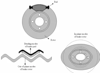
There are two types of brake squeal: low frequency and high frequency squeal. The difference between them is the mode shapes involved in the modal coupling mechanism. For the low frequency squeal, the modal coupling occurs between the out-of-plane modes of the rotor and bending modes of the brake pad. For the high frequency squeal, the modal coupling occurs between the in-plane modes of the rotor. The brake rotor is much stiffer in the in-plane direction than in the out-of-plane direction. Therefore, the resonance frequencies of the in-plane modes of the brake rotor are higher than those of the out-of-plane (bending) modes. Figure 1 shows the coupling possibilities between brake components.
Figure 1. Coupling possibilities between brake components.
Typically, the high frequency squeal occurs for frequency ranges between 8 and 16 kHz, while low frequency squeal occurs between 1 and 7 kHz. Since the human ear is most sensitive to the frequency region between 1 and 4 kHz, the low frequency squeal is considered the most annoying type of brake noise.
For these reasons, this paper attempts to evaluate control methods for the low frequency squeal problem using damping materials, and also procedures for selecting an appropriate damping material to fix a particular problem of low frequency squeal in an existing disc brake system.
Characterization of Brake Noise Generation
Perhaps one of the most important pieces of information from brake systems is the characterization of the noise generation via dynamometer or vehicle testing. Tests on vehicles are very imprecise, because it is impossible to control the variables like velocity, brake pressure and temperature in order to produce results that represent the characteristics of brake noise generation. On the other hand, dynamometer tests allow us to approach the real behavior of a brake system in practice, controlling parameters such as rotation, braking pressure and temperature while recording the sound pressure level and frequency of noise occurrences. The disc rotation is achieved by electric motors connected to a shaft with inertial wheels, simulating the inertia effects of the vehicle. Figure 2 shows of the components of an inertial brake dynamometer.
Figure 2. Components of an inertial dynamometer.
Measurements were taken for brake temperatures between 50 and 300 ºC. The braking pressure varied from 5 to 40 bar. The acquisition system stored the data of the brake events in blocks with the same temperature and pressure conditions, allowing a comparison between the different conditions to find regions of temperature and pressure where the noise occurs.
Each brake event lasts approximately 10 seconds. During this period, data were sampled in a certain number of autospectra of the microphone signal. The Sound Pressure Level (SPL) reported for each brake event is the maximum value measured among all autospectra.
Figure 3. Noise occurrences obtained with dynamometer test.
information is important to identify which class of noise problem is responsible for the high noise levels from the brake system.
Figure 4. Noise map for baseline brake system.
The next step is to determine the modal behavior of each brake component to verify whether any component has a resonance frequency near 7 kHz, and more importantly, to detect potential modal couplings between them. Therefore, a modal analysis procedure is applied for each component, i.e, rotor, pads and caliper, and the natural frequencies and mode shapes of these components are obtained.
Characterization of the Dynamics of Brake Components
Squeal noise occurs only when the brake system components demonstrate resonance vibrations (Boss and Balvedi, 2001). Therefore, it is very important to determine the modal behavior of the components to understand the problem.
Modal analysis of individual components allows us to gain an insight into potential coupling modes, which is, as mentioned before, one of the causes of squeal noise generation. In order to obtain the modal parameters of brake components, each one is modeled through a mathematical mesh to represent its geometry.
Pad, rotor and caliper Frequency Response Functions (FRF´s) were measured by exciting each component with an impact hammer and measuring the acceleration response with a small accelerometer. Then, the FRF´s were processed by CADA-X software in order to identify the modal parameters, i.e, resonance frequencies, modal shapes and damping values.
Modal Analysis of Brake Pads
The modal analysis of brake pads is perhaps the most important process to understand in order to find solutions for the disc brake noise problem. Some properties like loss factor, natural frequencies and mode shapes of brake pads are crucial in defining which type of brake noise problem may occur.
The brake pad was supported by two slender cables in order to simulate a free-free boundary condition. The free-free condition allows the structure to vibrate without interference from other parts, making the visualization easier of mode shapes associated with each natural frequency. Moreover, in this case, the rigid body oscillation frequency of the assembly (suspended pads) is much lower than the first natural frequency of the structure (pad). For instance, the assembly rigid body frequency is around 5 Hz, while the first natural frequency of the brake pad occurs around 2600 Hz.
Figure 5. Example of excitation autospectra used in the modal testing procedure.
The excitation was provided by a small impact hammer (PCB 086D02), with sensitivity of 22 mV/N and with a hard tip to achieve frequencies up to 16 kHz (see Figure 5). In order to avoid errors due to the effect of transducers in the dynamic properties of the brake pads (additional mass), a light small accelerometer (PCB 352B10), with sensitivity of 10 mV/g, was used to obtain the acceleration response. The accelerometer was kept at a fixed point (see Figure 6) and the excitation was applied at all points (roving method). The analysis was carried with 4096 data points, 16384 kHz of maximum frequency and frequency resolution of 4 Hz. An exponential time weighting function (window) was used for the response signal (5% decay and damping correction) and a transient window was used for the force signal. The modal parameters were extracted using the time domain method (least squares complex). Figure 7 shows the mode shapes and Table 1 presents the resonance frequencies and the damping loss factors obtained for the brake pad.
Figure 6. Mesh used for modal testing procedure of the brake pad.
Figure 7. Mode shapes for brake pad.
the modal coupling occurs between pad and disc bending modes, since the disc does not have a defined shape for twisting modes.
Table 1. Modal parameters obtained for brake pad.
Vibration Mode
Resonance Frequency (Hz)
Mode shape Damping Loss Factor (%)
1 2620 1st bending 0.678
2 3757 2nd bending 0.646
3 6650 3rd bending 0.641
4 7153 1st twisting 1.052
5 8623 2nd twisting 0.448
Modal Analysis of Disc
In the same way as that for the brake pad, the modal analysis of the disc was carried out. The mesh was constructed with 111 points to avoid space aliasing. During the measurements, the rotor was supported by a foam block, in order to simulate a free-free boundary condition. Experiments show that analysis with fixed boundary conditions, i.e, disc fixed on the brake knuckle by bolts, generates mode shapes very close in form to the mode shapes obtained for the rotor in the free-free condition.
The disc mesh represents only the border, because the disc hat and bolt area can be considered without influence on the coupling mechanism. Furthermore, the mode shapes found for these regions are located at high frequencies, beyond the frequency range of interest for the analysis of potential coupling modes. Figure 8 shows the modal shapes and Table 2 presents the natural frequencies and damping loss factors obtained for the brake disc in normal direction.
Figure 8. Mode shapes for brake disc.
The excitation was provided by an impact hammer in the normal direction. For this reason only the bending modes were obtained by this modal analysis. To obtain the modal parameters in the tangential direction, a new procedure is necessary. However, this paper addresses only modal coupling in the normal direction, i.e., between bending modes of the disc and pads, which, for the purpose
of this study, is sufficient. For this case, a modal analysis in normal direction is enough.
The pad presents less vibration modes than the disc, over the same frequency range. Furthermore, the damping loss factor values associated with the pad vibration modes are higher than those of the rotor, because the friction material provides considerably more damping than the cast steel used in the disc. As a consequence, there is a tendency for the disc modes to be the major determinant of the squeal frequency.
Table 2. Modal parameters obtained for brake disc.
Vibration Mode
Resonance Frequency (Hz)
Mode shape
Damping Loss Factor (%)
1 1090 2nd bending 0.247
3 2210 3rd bending 0.128
6 3600 4th bending 0.108
10 5320 5th bending 0.130
13 7320 6th bending 0.176
As mentioned before, squeal noise usually occurs whenever a number of brake components, such as pad and disc, start to vibrate together, creating a coupled system mode. Considering the bending modes coupling, when the components have the same wavelength and frequency, they will be geometrically matched and will vibrate in phase (Fieldhouse, 1999). In this case, the friction damping is minimized and the system works as a loudspeaker, radiating sound.
Analyzing the results obtained with the modal analysis of brake components together with their geometry, it can be noticed that the third bending mode of the brake pad and the sixth bending mode of the disc can couple and create a system mode. The third bending mode of the pad has a resonance frequency around 6650 Hz, while the disc resonance occurs at 7320 Hz for the sixth bending mode. The wavelength for the pad mode is approximately 100 mm and for the disc is 112 mm, considering these two bending modes, as shown in Figure 9.
Figure 9. Wavelength coincidence between disc and pad.
Figure 10. Modal coupling between modes of pad and disc.
Figure 11 shows a comparison between two frequency response functions, measured for rotor and pad. The third bending mode of the pad and the sixty bending mode of the disc are pointed out on the graph.
Figure 11. Frequency response functions for rotor and pad.
Behavior of Brake Components Under Pressure
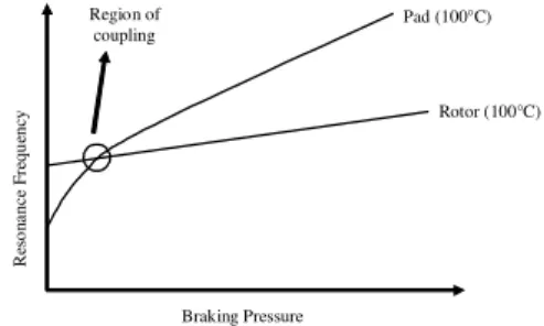
It should be noticed that the resonance frequency of the two modes involved in the potential coupling is slightly different. However, when the brake system works under pressure and temperature, the dynamics of the brake components are changed significantly. This behavior is more pronounced for the pad than for the disc, because of the friction material. The disc is made of cast iron while the brake pad has a significant proportion of friction material, which can be compressed by the brake pressure. Due to this compression, the stiffness of the pad is increased, moving the resonances to higher frequencies. On the other hand, the brake pressure has little influence over the disc. Therefore, the resonance frequencies of these two components change at different rates when brake pressure is applied(Triches et al., 2002), as shown in Figure 12.
R
es
o
n
a
n
ce
F
re
q
u
en
cy
Braking Pressure
Rotor (100°C) Pad (100°C) Region of
coupling
Figure 12. Influence of pressure on modes of disc and pad.
As a consequence, for high pressures, the third bending mode of the pad and the sixth bending mode of the rotor can start do vibrate together in a coupled mode. This fact is in accordance with Figure 4, which shows noise occurrence at higher pressures.
The effect of the braking pressure can be analyzed in terms of standing and traveling waves on the brake rotor. For the system here analyzed, at low pressures, rotor and pads are barely in contact. As contact pressure increases, the vibration amplitude peaks (on the mode shape) start to move with respect to the pads. In this case, there is a traveling wave in the disc. At high pressures, rotor and pad modes start vibrating in phase. In this situation, the anti-nodes no longer rotate, but remain in the same position along the rotor diameter, characterizing a standing wave.
Behavior of Brake Components in Relation to Temperature
Temperature has an effect similar to pressure. However, an increase in temperature causes a reduction in the stiffness of brake components. As a result, the resonance frequency of the brake components tends to decrease. In the same way as that for brake pressure, the effect of temperature is more important for the brake pad, again due to the presence of friction material. Figure 13 shows this effect for the brake pad resonance frequencies, considering the first and second bending modes.
Figure 13. Influence of temperature on modes of disc and pad.
For high temperatures, the third bending mode of the pad and the sixth bending mode of the disc tend to mismatch. Consequently, the modal coupling between these two modes doesn’t occur and squeal noise is not radiated. This also fact conforms with Figure 4, which shows that the high sound pressure levels appear for low temperatures and for high pressures.
Once the squeal noise mechanism is identified and the vibration modes involved in the problem are detected, noise control possibilities can be tested.
Constrained Layer Material
Low frequency brake squeal noise is due to the coupling between the bending modes of vibration of the disc and the pad. When the two components, disc and pad, start to vibrate together, the system damping for that specific system resonance is reduced, since the joint damping between pad and disc decreases (Balvedi et al., 2002). As a consequence, the friction forces may introduce more energy into the system than it can dissipate.
This class of squeal noise can be avoided with adequate design of the components, keeping the resonances apart. For this, changes in the geometry of the pad, like chamfers and slots, or changes in the mechanical properties of the components (stiffness, mass) can avoid possible modal couplings.
One can conclude that, even with changes in the geometry of the pad, pressure and temperature may contribute to the coupling of the same modes in a different boundary condition. Even more likely, modes formerly uncoupled may have closer frequencies and matched wavelengths, generating squeal at a different frequency.
In summary, modifications in geometry and material properties are not always effective to control this category of squeal noise. If the system generates more energy than can be dissipated, increasing the system damping can control the noise radiated. This additional damping can be obtained using constrained layer damping materials (called insulators).
Figure 14. Brake noise insulators.
Brake noise insulators consist of a sandwich of two steel plates separated by a viscoelastic or a rubber core, as seen in Figure 14, and its application to control brake noise has become one of the most efficient solutions. The insulator is very thin and it is bonded or mechanically attached to the pad backplate.
When the pad vibrates in the bending modes, a constrained layer material with a viscoelastic core bonded onto the pad backplate is submitted to mechanical deformations, converting part of the energy into heat by shear damping (Reddy, 1997), reducing the vibration amplitude of the component (see Figure 15).
Figure 15. Shear damping in constrained laminated materials.
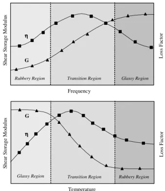
As previously stated, due to the behavior of friction material, brake pressure and temperature have a great influence on the characterization of the pad vibration modes and on its natural frequencies (Triches et al., 2002). So, for a brake system, the occurrence of squeal is a variable dependent on these two parameters. Other important point is that the viscoelastic or rubber material, which is used in the constrained layer, also has properties highly dependent on pressure, temperature and frequency. Young’s Storage Modulus characteristically decreases with an increase in temperature, while the loss factor reaches its maximum value at the transition temperature (Ungar et al., 1972), as shown in Figure 16. Frequency can have different effects, depending on the temperature region studied. In general, the loss factor tends to be proportional to frequency in the rubbery region, reach its maximum value in the transition region and tends to be inversely proportional to frequency in the glassy region. Pressure affects the phenomena of relaxation and recovery of the chains of polymers, changing the dynamic behavior of the viscoelastic materials. Therefore, the suitable damping material selected must be appropriate for the conditions under which squeal occurs.
Glassy Region Transition Region Rubbery Region
G ηηηη Temperature L o ss F a c to r Glassy Region Transition Region Rubbery Region G ηηηη Frequency L o ss F ac to r S h e ar S to ra g e M o d u lu s S h ea r S to ra g e M o d u lu s
Figure 16. Effect of temperature and frequency on the properties of viscoelastic materials, where G is the storage modulus (real part of the complex modulus) measured for shear deformation (Jones, 2001).
Considering the dynamometer tests, for the particular brake system here analyzed, squeal noise occurs at a frequency around 7000 Hz, and within temperature and pressure ranges of 150 – 175
°C and 25 – 30 bar, respectively. Therefore, the proposed insulator must have a good performance under these conditions.
Selection of Insulators
The classical method for selecting an insulator to reduce the squeal noise problem is the simulation of the brake event in an inertial dynamometer. A set of insulators is tested and the results are analyzed. The insulator which presents the best noise reduction is chosen. However, this method is very expensive and time consuming. Besides that, it doesn’t provide an insight into the mechanism of squeal noise generation.
This paper presents a methodology for selecting an insulator based on modal screening. The proposed methodology reduces the insulator selection time significantly and allows for an optimum use of the brake dynamometer to validate selected insulators. Hence, the dynamometer is used only to validate the insulator selected by the modal screening method, saving time and reducing costs.
Knowing the characteristics of the squeal problem (frequency, temperature and pressure at which the noise occurs), the brake insulator can be selected through the dynamics of the brake components.
The purpose of brake shims is to add damping to the brake pad and, consequently, to the whole brake system. Therefore, the capacity of an insulator to add damping can be evaluated through mobility measurements on the brake pad, for a range of temperature. For this, different types of insulators were bonded to the pads and measurements of Frequency Response Functions (FRF’s) were carried out inside an oven, to evaluate the changes in loss factor.
was evaluated for the third bending mode of the pad, for different types of insulators. In order to get the loss factor, point mobility functions were measured for a range of temperature between 75 and 300 °C. Figure 17 shows the results obtained for the pad loss factor of four types of insulators, evaluated for the third bending mode of the pad.
Figure 17. Loss factor for the pads using different insulators under temperature.
Notice that for temperatures around 150 °C insulator # 2 shows the best performance in terms of loss factor added to the brake pad. However, the capacity of the insulators to add damping to the whole system also needs to be verified. Thus, frequency response functions of the assembled system were measured, evaluating the dynamic properties of the system resonance, around the frequency of the sixth disc bending mode. Frequency and, more importantly, damping of this mode were measured as a function of brake pressure. This approach allows the analysis of the performance of the insulator under different boundary conditions of the brake system.
Analysis of Assembled Brake System
The frequency response analysis of the assembled brake system was performed for a determined range of brake pressure. This technique allows the quantifying of the damping of the system at the critical mode for each insulator configuration. This test provides the level of damping in the system and effect on the noise problem.
The technique consists of measuring frequency response functions at points of disc and external pad, exciting the disc using an impact hammer. In this experimental method, the disc remains static. As a consequence, the friction mechanism was not taken into account. Thus, the input energy introduced by the friction between pad and disc is replaced by the excitation provided by the impact hammer. This is a simplification, because in real systems the excitation is not kept constant but varies as a function of the boundary conditions of the brake system. However, since the excitation provided by the frictional contact between rotor and pads has a broadband feature, the point force provided by the impact hammer can be used to represent the behavior of the input excitation energy (McDaniel et al., 1999).
This technique allows the measurement of the system damping considering exclusively the mode coupling phenomena. Figure 18 shows a sketch of the test setups.
Figure 18. Setup for measurement of system Frequency Response Function (FRF) as a function of pressure.
In this way, having determined the main modes responsible for the squeal noise generation, the system loss factor can be evaluated for different shim configurations. Moreover, quantifying the system loss factor makes it possible to predict the potential for squeal occurrence and which shim fits better for a specific problem.
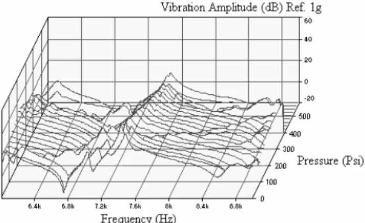
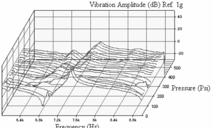
The point frequency responses for the disc were taken at the same position for all measurements and for different lining pressures, in steps of about 25 Psi and at room temperature. Figure 19 shows a waterfall plot of the frequency response functions for the baseline system, without noise insulators.
Figure 19. Frequency response measurement on the assembled system with baseline pads.
Observe that the resonance frequency (7200 Hz) occurs in the vicinity of the squeal frequency measured in the dynamometer. Notice also that the assembled brake system with pads in the baseline condition has a system loss factor, for the mode of interest, in the order of 0.01, which is considered low.
Figure 20. Loss factor obtained for assembled brake system.
Under the described conditions, it is necessary to increase the system damping to avoid the squeal noise radiation. With this purpose, insulator # 2 was bonded to the pad backplate and the aforementioned procedure was repeated.
With insulator #2, the system loss factor increases (see Figure 20) and the amplitude of vibration decreases, as shown in Figure 21.
A significant gain in the system damping can be seen when noise insulators are used, mainly in the pressure range where the modal coupling occurs. For high pressures, the damping loss factor had its value multiplied by three. Besides this, it is important to remember that the frequency response measurements were carried out at room temperature, while insulator # 2 shows the best performance around 150 °C.
Figure 21. Frequency response measurement on the assembled system with noise insulator #2.
Therefore, for the brake system analyzed here, insulator #2 would be the best choice. To confirm the performance of the selected insulator, new dynamometer tests were performed. The results are shown in Figure 22, which illustrates that the noise at the frequency around 7 kHz has lower amplitude than that for the baseline condition, when the brake system has no noise insulators.
Figure 22. Noise map for brake system using noise insulators.
Furthermore, the number of noisy stops for the brake system using noise insulators was much lower than for the baseline brake system, as shown in Figure 23.
% > 100 dB % > 90 dB
% > 80 dB
% > 70 dB
Brake system with insulator # 2 Baseline brake system 0
5 10 15 20 25
%
o
f
n
o
is
y
o
c
c
u
rr
e
n
c
e
SPL
Brake system with insulator # 2 Baseline brake system
Figure 23. Noise occurrences for brake system with insulator # 2 and for baseline condition.
In summary, a suitable noise insulator for a particular brake system was selected using two dynamometer tests. Furthermore, the modal screening method allowed gaining an insight into the mechanism of squeal noise generation.
Conclusions
Despite a century of developing disc brake systems, disc brake squeal remains a largely unresolved problem. This is not to say, however, that no progress has been made. Many experimental and analytical studies have led to insight on the factors contributing to brake squeal or to the amelioration of squeal in disc brakes of a specific type or in a particular make and model of automobile. Experimental studies have accumulated a wealth of information about the nature of squeal, the vibration modes therein, the wear of brake components and frictional interactions in brakes.
The design of modifications to a given brake system to control noise has too often been regarded as a “cut and paste or trial and error” procedure, where the effects of a huge matrix of modifications is experimentally evaluated on a structure. This approach is sometimes successful but always expensive and time consuming. Often, no knowledge is gained even if a solution is found.
variation on the squeal noise frequency. This was attributed to the strong dependency of the system braking parameters to the operating boundary conditions of the brake system, especially braking pressure and temperature. This phenomenon was also seen during the static system frequency response measurements, where the third bending mode of the pad and sixty bending mode of the disc, originally separated by 760 Hz, moved closer as function of braking pressure.
The modes involved in the coupling mechanism were pointed out through modal analysis and frequency response function measurements. Together with the information provided by the initial dynamometer test, this experimental procedure could be applied as an effective tool for selecting damping materials to fix a specific problem.
The application of constrained layer materials to add damping to the brake system can be considered as an efficient solution to reduce the squeal noise problem. The final dynamometer test showed reductions about 20 dB for some frequencies, in the case of the system using the selected insulators. However, the selection of the insulator is not a straightforward procedure and must take into account the effects of temperature and brake pressure.
To avoid excessive time consumption with extensive dynamometer tests (trial and error procedure), the use of modal analysis and frequency response function measurements is recommended, since its effectiveness was demonstrated by the procedures shown in this paper.
Acknowledgments
The authors would like to thank Dr. Alessandro M. Balvedi, for his helpful comments and recommendations about frequency response measurements of the brake system under pressure, and Dr. Sharam Tousi, for his help with the dynamometer tests. This work was jointly supported by the Brazilian agency CNPq – Conselho Nacional de Desenvolvimento Cientifico e Tecnologico, and the
company MSC Laminates and Composites. The authors also thank the software suppliers LMS International and Smarttech.
References
Triches, M. J. et al, “Application of Constrained Layer Material on the Reduction of Disc Brake Noise,” Proc. of INTER-NOISE 2002, edited by Ahmet Selamet, Rajendra Singh and George C Maling, Jr. (Dearborn, MI, August 19-21, 2002).
Papinniemi, A., Lai, J. C. S., Zhao, J. and Loader, L., “Brake Squeal: a literature review,” Applied Acoustics, 63, 391-400 (2002).
Dunlap, K. B., Riehle, M. A. and Longhouse, R. E., “An Overview of Automotive Disc Brake Noise,” SAE Paper 1999-01-0142 (1999).
Chung, C., Steed, W., Kobayashi, K. and Nakata, H., “A New Analysis Method for Brake Squeal Part I: Theory for Modal Domain Formulation and Stability Analysis,” SAE Paper 2001-01-1600 (2001).
Dihua, G. and Dongying, J., “A Study on Disc Brake Squeal Using Finite Element Methods,” SAE Paper 980597 (1998).
Abdelhamid, M. K., Blaschke P., Wang, W. A. e Yang, S., “An Overview of NVH Problems in Braking Systems,” Book of 5th International
Brake Colloquium, (2001), pp. 41-47.
Boss, D. E. and Balvedi, A. M., “Engineering Brake Noise Solutions”,
Book of 5th International Brake Colloquium, (2001), pp. 32-35.
Fieldhouse, J. D., “A Proposal to Predict the Noise Frequency of a Disc Brake Based on the Friction Pair Interface Geometry,” SAE Paper 1999-01-3403 (1999).
Balvedi, A. M., Gerges, S. N. Y. and Tousi, S., “Identification of Brake Squeal Noise via Sound Intensity and Acoustical Measurement,” Proc. of INTER-NOISE 2002, edited by Ahmet Selamet, Rajendra Singh and George C Maling, Jr. (Dearborn, MI, August 19-21, 2002).
Reddy, J. N., Mechanics of Laminated Composite Plates: Theory and
Analysis (CRC Press, 1997).
Lu, Y. P., Killian, J. W. and Everstime, G. C., “Vibrations of Three Layered Damped Sandwich Plate Composites,” Journal of Sound and Vibration, 64 (1), 63-71 (1979).
Ungar, E. E., Heckl, M. and Cremer, L., Structure Borne Sound (2nd Edition, Springer-Verlag, Heidelberg, 1972).
Jones, D. L. G., Viscoelastic Vibration Damping, (John Wiley & Sons, Ltd, 2001).