ABSTRACT: The objective of this research was to design pilot helmets and to perform analysis of designed ballistic helmet against impact strength of bullet in Solidworks and Laminator software. The material used for construction of the helmet is iber reinforced polymer matrix composite in which polymer matrix is made of nylon, a thermoset resin, and the ibers are aramid, an aromatic polymide resin developed by E.I. duPont de Nemours and Company and sold under the trademarks “Kevlar®” and “Nomex®”. The design of the helmet is done by deciding the stacking sequence of various laminae which are oriented with main material directions at different angles to the global laminate axes in order to produce a structural element in the form of a shell. The simulation of the helmet in Solidworks and Laminator is done with an 8-g AK 47 bullet, hitting it with a velocity of 710 m/s. The model is validated against published data and a good correlation is observed. The result of this project is that a 1.30 kg helmet with shell thickness of 7 mm is obtained, which is economical, light weight and is able to give high-performance protection against ballistic shrapnel and bullets.
KEYWORDS: Finite element analysis, Pilot helmets, Thermoplastic aramid, Composite materials.
Finite Element Analysis of Pilot’s Helmet
Design Using Composite Materials for
Military Aircraft
Puran Singh1, Debashis Pramanik2, Ran Vijay Singh2
INTRODUCTION
The sizing, it, and comfort have been the most frequent concern of the aviators in each of the different types of aircraft squadrons. Pilot helmet has been used as protective equipment in order to shield human head against serious injuries from shrapnel and bullets. Most modern ballistic helmets are made from a plurality of plies of ballistic material which are laid up in a mold and shaped to the coniguration of the helmet. Pilot helmet made of composite materials has become a better equipment compared to traditional steel helmet in terms of the reduction in weight and the improvement in ballistic resistance. Therefore, inite element analysis can be used as a method to characterize the response of composite pilot helmet and to obtain valuable information on parameters affecting impact phenomena (Othman 2009). The irst dimension of the helmet is decided according to the average size of human head (Figure1).
In general, there are two ballistic test standards that are used to determine the quality of protection of the helmet: (1) NIJ-STD-0106.01 Type II and (2) MIL-H-44099A. Nevertheless, different helmet manufacturers may have diferent ballistic test methods.
Helmet improvement around the head and over the eyes during air combat maneuvers (ACM) or sharp turns in light involves positive “G” forces in excess of 2 “G”. his is attributable to the poor proile of the helmet and its misplaced center of gravity (CG).
he main focus of this research is to study the response of pilot helmet made of composite materials when impacted
1.Amity School of Engineering & Technology – Mechanical & Automation Engineering Department – FEM Laboratory – New Delhi/Delhi – India. 2.Manav Rachna International University – Faculty of Engineering Technology – Mechanical Engineering Department – Faridabad/Haryana – India.
Author for correspondence: Puran Singh | Amity School of Engineering & Technology – Mechanical & Automation Engineering Department – FEM Laboratory | 580, Najafgarh Kapashera Rd, Dalmia Vihar, Bijwasan | 110061 – New Delhi/Delhi – Índia | Email: [email protected]
at high velocity for diferent sequences of lamina or plies by using inite element analysis. he objectives of this research are: • To design a pilot helmet that provides high performance
protection against ballistic shrapnel and bullets. • To design a light-weight and economical pilot helmet. • To analyze deformation as well as stress distribution
of the helmet when struck by a bullet at a velocity of 710 m/s.
• To evaluate the failure mechanism occurred on pilot helmet ater the impact.
ballistic materials. Figure 2 is a basic summary of U.S. helmet designs and materials since World War I (WWI). For example, the helmet design in WWI was signiicantly diferent than in World War II (WWII). WWI was characterized by an unprecedented amount of trench warfare, and the hot and sharp debris falling from relatively high angles were typical. his gave rise to the fairly wide “brim” that gave the WWI helmet its distinctive look.
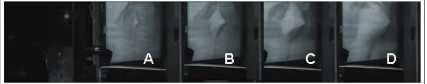
he combined shells provided higher protection levels over a greater coverage area than the previous M1917 copy of the British Mk I “Brodie” helmet of WWI. he one-size M1 helmet weighed 1.55 kg, had 0.12 m2 of surface coverage, and protected against the 0.45 caliber round at 244 m/s with a 50% ballistic limit of 396 m/s against the standard North Atlantic Treaty Organization (NATO) 1.1-gram fragment simulator. Thermoplastic aramid matrix systems, one of the most commom materials used, have excellent, mass-efficient ballistic properties. However, the thermoplastic matrix is typically 30 to 60% less rigid than even the toughened thermoset (e.g. phenolic) matrix. his has signiicant implications for the overall static structural stability and resilience of the thermoplastic aramid shell, as well as the dynamic delections associated with a ballistic event. To illustrate this phenomenon, consider Fig. 3. A Phantom v.7 high-speed digital camera was used to capture the efects of a simulated ballistic fragment impact on the back side of a lat thermoplastic aramid panel.
his panel had an areal density that was nearly 50% of that recommended for producing a helmet shell. As can be seen in 160.581
41.034
38 82.407
Figure 1. Front view showing dimensions of the helmet.
HELMET DESIGN AND MATERIAL
CONSIDERATIONS
Helmet materials and designs have evolved primarily in light of prevailing threats and the invention of new and improved
PVB: Polyvinylbutyral; PASGT: Personal armor system for ground troops; MICH: Modular integrated communication helmet; FFW: Future force warrior.
Figure 2. Historical perspective of U.S. Army helmet design and materials (Walsh et al. 2005).
Steel
WWI WWII–Korea Vietnam PASGT MICH FFW
Kevlar
®
/PVB phenolic New materialsthe sequence of images, the fragment is efectively contained and stopped but not before it induced signiicant deformation to the overall panel.
A thermoplastic Kevlar® shell at this low areal density may be well-suited for certain applications, but given that the deformation is well over 1 in, it could cause severe skull fracture (and possibly death).
he primary goal of the helmet shell is to protect the pilot from a variety of threats. First, the requirement is to limit the perforation by fragments or bullets through the helmet. Even if the fragment is stopped, the delection of the shell can engage the skull and cause injury. he current PASGT uses an efective air gap of approximately 13 mm between the inner shell wall and the soldier’s head to accommodate any delection during projectile arrest.
Transient deformation is a direct result of the kinetic energy being dissipated within the ballistic material. Fabrics, although extremely ballistically resilient at real densities around 0.975 g per cm2, tend to deform signiicantly. he fragment or bullet could conceivably be arrested by the fabric, but the resulting deformation could still result in a fatal injury by adversely engaging the skull. By contrast, thermoset composites, such as polyvinylbutyral (PVB) phenolic aramid systems, reduce the transient deformation, even though their ballistic performance may be less than that of a pure fabric system. hermoplastic composite materials offer a compromise of fabric and thermoset composite performance. hat is, the thermoplastic tends to deform but not as much as pure fabric, and it tends to have better ballistic resistance than a thermoset-based composite material (Campbell and Cramer 2008).
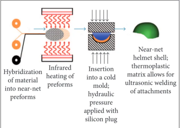
Practical durability is a necessary trait for any article used in combat. Helmets must also pass static structural tests as well. “Ear-to-ear” loads of 2,000 to 3,500 kPa must be withstood by the helmet for several cycles without any permanent deformation in its structure. hermoset composites tend to do well, given the higher matrix modulus (as compared to a thermoplastic matrix). Fully realizing the material and performance beneits of thermoplastic aramids and hybridized solutions will require the rethinking of the manufacturing processes currently in use by most of the U.S. helmet manufacturers. Current processes are conigured for mass production of thermoset-based, monolithic Kevlar® helmets. hese manufacturing systems typically use expensive, matched steel tools to consolidate the materials. Cold helmet pre-forms are placed in a hot mold and held under pressure until fully cured. Figure 4 is a conceptual schema of such a process.
he composite consists of two or more constituents. One is called matrix and the other, reinforcement. The main functions of matrix are:
• It binds the ibers (reinforcement) together and transfers the load to ibers. It provides rigidity and shape to the structure.
• It isolates the ibers so that an individual iber can act separately. his helps to stop propagation of cracks. • It provides good surface inish quality and protection
to reinforcement ibers against chemical attack and mechanical damage (wear).
• Failure mode of composite is strongly afected by the type of matrix material,and performance characteristics, such as ductility, impact strength etc., are also inluenced. Reinforcement is an important constituent of composite materials. Fiber reinforcement is a thin rod-like structure (Fig. 5). The main functions of fiber reinforcement are:
• It carries the load. In structural composites, 70 to 90% of the load is carried by iber reinforcements. • It provides stifness, strength and thermal stability to
the composite.
• It provides electrical conductivity or insulation, depending on the iber used in the composite. he general properties of composite materials are light weight, low thermal expansion, high stifness, high strength and high fatigue resistance.
he matrix in a reinforced plastic may be either thermoset or thermoplastic. In the early days nearly all the thermoset moulding materials were composites in that they contained fillers such as wood flour, mica, cellulose etc. to increase
Hybridization of material into near-net preforms Infrared heating of preforms Insertion into a cold
mold; hydraulic pressure applied with silicon plug Near-net helmet shell; thermoplastic matrix allows for ultrasonic welding
of attachments
Figure 4. Conceptual schema of the production process of
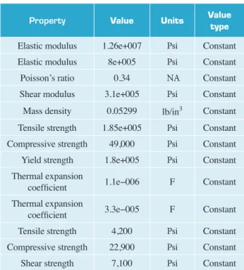
Property Value Units Value type
Elastic modulus 1.26e+007 Psi Constant
Elastic modulus 8e+005 Psi Constant
Poisson’s ratio 0.34 NA Constant
Shear modulus 3.1e+005 Psi Constant
Mass density 0.05299 lb/in3 Constant
Tensile strength 1.85e+005 Psi Constant
Compressive strength 49,000 Psi Constant
Yield strength 1.8e+005 Psi Constant
Thermal expansion
coeficient 1.1e−006 F Constant
Thermal expansion
coeficient 3.3e−005 F Constant
Tensile strength 4,200 Psi Constant
Compressive strength 22,900 Psi Constant
Shear strength 7,100 Psi Constant
Table 1. Properties of Kevlar® 149/epoxy.
their strength. However, these were not generally regarded as reinforced materials in the sense that they did not contain ibers. Nowadays the major thermoset resins, used in conjunction with glass iber reinforcement, are unsaturated polyester resins and, to a lesser extent, epoxy resins (Piggott 1980). he most important advantages which these materials can ofer are: (i) they do not liberate volatiles during cross-linking and (ii) they can be moulded using low pressures at room temperature.
A wide variety of thermoplastics have been used as the base for reinforced plastics. hese include polypropylene, nylon, styrene-based materials, thermoplastic polyesters, acetyl, polycarbonate, polysulfone etc. The choice of a reinforced thermoplastic depends on a wide range of factors which include the nature of the application, the service environment and costs. In many cases conventional thermoplastic processing techniques can be used to produce moulded articles.
• It is assumed that the impact time of the bullet on the
helmet is 1.5 ms, i.e. the bullet comes to rest 1.5 ms after hitting the surface of the helmet.
• The impact of the bullet on the helmet is assumed to
be uniaxial (along x-axis).
• For applying the boundary conditions of the helmet
during analysis, the bottom part of the helmet is ixed. • he shape of the bullet is not taken into account while
calculating the force of the bullet on the helmet. he dimensions of the helmet are: width — 180.00 mm, height — 160.58 mm and length — 180.00 mm (Fig. 6).
The composite material chosen is Kevlar® 149/epoxy (iber/ matrix) whose material properties are mentioned in Table 1. Various laminae are prepared out of this composite material,
180
180
Figure 5. Types of reinforcement.
DESIGN CALCULATIONS AND ANALYSIS
he following assumptions have been taken while designing and analyzing this project:
• It is assumed that the velocity at which the bullet
hits the helmet surface is the same as the muzzle velocity.
Figure 6. Top view showing the dimensions of the helmet.
hermoplastic or thermoset matrix
Particulate iber
Particulate composite (Quasi-isotropic)
Unidirectional short iber composite
Random short iber composite (Quasi-isotropic)
Unidirectional continuous iber
composite
Bidirectional continuous iber composite
Multidirectional continuous iber composite (Quasi-isotropic)
Discontinuous ibers
Continuous ibers
and the stacking of various laminae is done, which is oriented with principal material directions at different angles to the global laminate axes producing a structural element in the form of a shell. The strength of this shell is analyzed when a bullet, at a certain velocity, hits it (Silva et al. 2005).
The speciication of the bullet is as follows: AK 47; caliber: 7.62; mass: 8 g; muzzle velocity: 710 m/s. The force exerted on the helmet is: m × a = 8 × 10−3 × (710/0.0015) = 3,786.667 N. The force with which the bullet hits the helmet is approximately taken as 4,000 N along the x-axis.
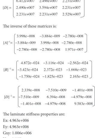
Here a software called Laminator is used, which takes the abovementioned material properties, load applied (4,000 N) and different angles of each lamina as the input. It calculates the [A],
[B] and [D] matrices and the inverse of these matrices, as well as laminate stiffness properties. Each stacking sequence has 24 laminae. The material of each ply is the same and their thickness is taken as 0.21 mm. This process is repeated for several combinations.
STACKING SEQUENCE 1
Ater applying the load and deining the boundary conditions to the helmet with the given stacking sequence, a simulation was made to run. he following plots in the form of results were obtained and studied to ind the optimum coniguration.
Stacking sequence 1: [(45)4, (0)4, (90)4] s with each lamina thickness of 0.21 mm. [A], [B] and [D] matrices are:
he inverse of these matrices is:
he laminate stifness properties are: Ex: 4.963e+006
Ey: 4.963e+006 Gxy: 1.006e+006 Vxy: 0.097
We have similar stacking sequence for 2, 3, 4, 5, and 6.
After applying the load and deining the boundary conditions to the helmet with the given stacking sequence, a simulation was made to run. The following plots in the form of results were obtained and studied to ind the optimum coniguration.
Firstly, taking the dimensions for the ballistic helmet, three circular sketches were made. By using those circular sketches as a guiding proile and carefully adjusting various parameters, a shell was formed with the help of surface lot feature (Fig. 7a).
Figure 7. Helmet coniguration. (a) Shell forming; (b) Helmet with the support structure; (c) Deining composite layers;
(d) Fixed support at the bottom; (e) Application of force; (f) Meshing; (g) Displacement distribution.
(a) (c) (e)
(g)
Figure 8. Analysis results. (a) Displacement plot for [(90)4, (0)4, (90)4] s; (b) Stress plot for [(90)4, (0)4, (90)4] s; (c) Strain plot for [(90)4, (0)4, (90)4] s; (d) Factor of safety plot for [(90)4, (0)4, (90)4] s.
Selection set Unit Sum of X Sum of Y Sum of Z Resultant
Entire body N −2,403.53 0.100185 −0.00871483 2,403.53
Entire body N −2,403.56 −0.0747453 −0.00140771 2,403.56
Entire body N −2,403.56 −0.0443136 −0.00578333 2,403.56
Entire body N −2,403.49 0.140461 0.0142988 2,403.49
Entire body N −2,403.57 −0.00499602 0.000274185 2,403.57
Entire body N −2,403.53 0.0195969 −0.00771621 2,403.53
Table 2. Reaction forces.
For analysis purposes, a support structure was designed to provide the fixture support at the sides of pilot helmet (Fig. 7b). This support works similarly to the straps provided for the support of the helmet in real time.
Linear elastic orthotropic material Kevlar® 149 is defined for all the layers (Fig. 7c). The bottom part of the helmet along with the designed vertical fixtures are fixed and used as boundary conditions for analysis purposes (Fig. 7d). Now, after defining the boundary conditions, the calculated force is applied (Fig. 7e) at the target point taken (where the bullet will hit the helmet). A fine high-quality mesh (with approximate element size equal to 7.9 mm) is generated having parabolic triangular elements with 10,354 nodes and total number of elements equal to 5,058 (Fig. 7f ). Results in the form of stress distribution, strain distribution, displacement distribution and factor of safety distribution are obtained and analyzed (Fig. 7g).
ANALYSIS RESULTS
Displacements are measured in meters from the position where the bullet hits the helmet surface before any deformation occurs (Fig. 8a).
Distributions of von Mises stresses are shown in the stress plot obtained ater running the simulation (in N/m2). In this case, a material is said to start yielding when its von Mises stress reaches a critical value known as yield strength. he von Mises stress is used to predict yielding of materials under any loading condition from results of simple uniaxial tensile tests (Fig. 8b).
he plot in Fig. 8c shows the distribution of strain in the top part of pilot helmet when the bullet hits the surface. he plot in Fig. 8d shows the factor of safety at every node. Factor of safety (FoS) is a term describing the structural capacity of a system beyond the applied or actual loads. Tsai-Hill failure criterion
is used to evaluate the FoS at the top part of pilot helmet (composite shell). his criterion considers the distortion energy portion of the total strain energy that is stored due to loading. he reaction forces are shown in Table 2. It has proposed that
(a)
(b)
(c)
Serial
number Sequence Ex Ey Gxy Vxy FoS
1 [(45)4, (0)4, (90)4] s 4.963e+006 4.963e+006 1.006e+006 0.097 21
2 [(0)4, (90)2, (0)2, (45)2, (0)2] s 8.857e+006 2.959e+006 7.074e+005 0.152 14
3 [(90)2, (0)2, (45)2, (0)2, (90)2, (0)2] s 6.903e+006 4.934e+006 7.263e+005 0.092 17
4 [(90)2, (0)2, (45)2, (0)2, (90)2, (0)2] s 4.821e+006 1.033e+006 8.338e+005 0.454 6.8
5 [(90)4, (0)4, (90)4] s 4.760e+006 8.715e+006 3.100e+005 0.031 17
6 [(0)2, (45)2, (90)2, (0)2, (45)2, (90)2] s 4.963e+006 4.963e+006 0.097 0.097 20
Table 3. Coniguration by analysing the results of both Laminator and Solidworks simulations.
there should be four helmets to suit light requirements. Ater the careful study and comparison of diferent composite layer combinations in Solidworks and Laminator, the most optimum coniguration is shown by stacking sequence 1 — [(45)4, (0)4, (90)4] s, as can be seen in Table 3.
CONCLUSIONS
It has been concluded that the pilot helmet with 24 layers (each layer with 0.21 mm) with total thickness equal
to 5.04 mm provides the optimum configuration with the best combination of laminate stiffness properties and FoS (Chawla 1998) under the specified testing conditions (8 g bullet travelling with 710 m/s velocity). The weight of the helmet shell comes out to be 300 g but, in order to give stability and comfort, certain features like foam padding, straps etc. are provided, which increases the weight of the helmet to approximately 1 kg.
he stacking sequence 1 [(45)4, (0)4, (90)4] s, is found as the optimum coniguration by analysing the results of both Laminator and Solidworks simulation.
REFERENCES
Othman RB (2009) Finite element analysis of composite ballist helmet subjected to high velocity impact (Master’s thesis). Penang: Universiti Sains Malaysia.
Chawla KK (1998) Composite materials: science and engineering. New York: Spinger-Verlag.
Silva MAG, Cismaşiu C, Chiorean CG (2005) Numerical simulation of ballistic impact on composite laminates. Int J Impact Eng 31(3):289-306. doi: 10.1016/j.ijimpeng.2004.01.011
Piggott MR (1980) Load bearing ibre composites. Oxford: Pergamon Press.
Campbell DT, Cramer DR (2008) Hybrid thermoplastic composite ballistic helmet fabrication study. Glenwood Springs: Fiberforge Corporation.
![Figure 8. Analysis results. (a) Displacement plot for [(90)4, (0)4, (90)4] s; (b) Stress plot for [(90)4, (0)4, (90)4] s;](https://thumb-eu.123doks.com/thumbv2/123dok_br/18889797.424741/6.926.478.826.258.823/figure-analysis-results-displacement-plot-s-stress-plot.webp)
