ABSTRACT: This paper describes the polycarbonate acrylic laminated development that can be applied in aeronautics and aerospace transparencies. The case studied is a laminated double-curved transparency (bubble form) used in an observation side window of a military aircraft. Side windows need strength and speciic characteristics, similar to windshields, allowing the perfect visualization and image capture. Laminated transparencies composed by different materials have better qualities than the monolithic ones. This kind of transparency can offer high mechanical and chemical resistance, high transparency, no fragmentation and easy maintenance or recovery. A signiicant amount of information about materials and processes was jointed in order to build the reinforced transparency and validate this study. The inal results were analyzed based on two points of view: mechanic resistance and, especially, optical quality.
KEYWORDS: Transparency, Laminated polycarbonate, Acrylic, Window.
Reinforced Transparencies for Aerospace
Application – Case Description
Melis De Bruyn Neto1, Rita de Cássia Mendonça Sales1,2, Koshun Iha1, José Atílio Fritz Fidel Rocco1
INTRODUCTION
Whenever it is necessary to see or capture images through a protective barrier, it arises the need to deine it and build it as efectively and eiciently as possible. he problem that comes from this observation is to measure all the variables that can inluence the requirements and, mostly important, to deine the materials that can be used, as well as the methods and processes that will lead to the manufacture of a quality product. he materials chosen, suitable for the construction of reinforced transparencies for aerospace industry, as windshields, must to be taken into account, as well as all loads they are subjected to, including structural terms, mechanical and thermal loads (Fam and Rizkalla 2006). In addition, superior optical characteristics are also essential (Fixler 1977).
The modern engineering and architecture “design” requires glazing materials that ofer high levels of safety and high-performance mechanical properties. hese properties include: ballistic resistance; wind loads; explosion; and physical attacks resistance. In some applications, noise level reduction, solar radiation resistance, and thermal barrier behavior are also desirable. he laminated glazing is the union of multiple layers of various materials such as glass, polymeric ilms, resins, and lexible sheets of transparent polymers (polycarbonate and/or acrylic), usually applied to obtain complex geometric shapes (Fixler 1977; Smith et al. 1996).
It is necessary a prior knowledge of the physicochemical properties of the engineering materials to make the right choice for each application. To the right choice, it is necessary to know the load or the efort to which the transparency must resist and the kind of efort that will be neutralized by the transparent barrier. However, it should be clear that there will always be an efort
1.Departamento de Ciência e Tecnologia Aeroespacial – Instituto Tecnológico de Aeronáutica – Divisão de Ciências Fundamentais – São José dos Campos/SP – Brazil.
that can overcome the barrier, because there is no deinitive mechanical barrier. hus, the barrier will be “strengthened” until reaching the desired resistance and including a safety factor.
Besides the mechanical strength, transparent barriers must have optical quality, being able to see or capture images by means of high light transmission level, with a minimum deviation or absorption, until the images reach the observer’s eye or the image capture device.
Reinforced transparencies are not only intended to prevent a mechanical failure, but to perform with maximum eiciency and preferably not releasing fragments that reach whom or what will be protected by the transparent barrier. he objective of this study was to describe the information needed to design and to construct a reinforced transparency for aerospace application made with polymeric materials, which is part of the “observation window” of a military patrol aircrat.
MATERIALS AND METHODS
MATeRiAlS ChoiCehe materials chosen for the observation window were based on MIL-PRF-5425E (1998) and MIL-P-46144C (1986). he chosen structural materials, in sheet form, were: acrylic or polymethylmethacrylate – PMMA (ASTM D4802-02) (Modiied “cast” acrylic ACRYLITE® 249, CYRO Ind, USA); polycarbonate – PC (Fox and Christopher 1962; LeGrant and Bendler 2000) (LEXAN® 9034, GE-Plastics, USA); and, for bonding, in ilm form, polyurethane – PU (KRYSTALFLEX®PE399, Huntsman, USA), which is the material that allows a good adhesion between acrylic and polycarbonate.
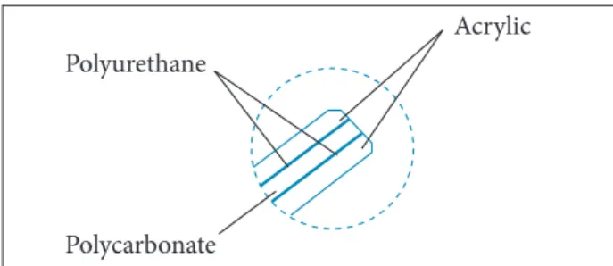
he following sequence was used to prepare the specimens: two outer layers with 3.18 mm thickness of acrylic (PMMA); a central PC layer with 6.35 mm thickness; and between acrylic and PC layers, two aliphatic PU layers with 1.27 mm thickness were inserted. In other words, the final composition was: PMMA + PU + PC + PU + PMMA (Fig. 1).
TeMpeRATuRe ReSiSTAnCe TeST
Two samples with nominal size (20 × 10 cm) were prepared and laminated in the same way of the shearing test samples. he samples were submitted to 100 °C for 50 min, using a circulating air oven (Kamp).
SpeCiMenS pRepARATion
All the raw material plates were cut into dimensions much larger than the inished parts, using a circular saw. Ater this process, the plates were dehumidiied at 100 °C, during 6 h in an air circulating oven.
he dehumidiied materials were laminated in the sequence previously deined. A vacuum bag was prepared around the laminated (all the bagging materials are from Airtech®, USA; vacuum ilm and sealant tape). he set, formed by the laminate and the vacuum bag, was placed in an autoclave (FERLEX®, Brazil) to be bonded. To ensure the bonding material, the set formed by the laminate and the vacuum bag was heat-treated to 120 °C for 2 h at a 2 °C/min heating rate and pressured at 0.7 MPa inside the autoclave. he temperature and pressure were maintained during 3 h; then, it was cooled until the ambient temperature was reached. At the end, the pressure was released and the cycle, inished.
TheRMofoRMing pRoCeSS
Ater autoclave process, the set was placed on a tool designed for the observation window manufacture. he tooling (Fig. 2) was heated to 180 °C at a 6 °C/min heating rate. After the laminate reached the melting point, it was blown at a pressure of 0.14 MPa to achieve its deinitive new shape. he specimen was then cooled at 2 °C/min.
he part trimming was performed in a conventional manner using bandsaw and sander. he polishing was done using ine inishing hand tools and then through sandpapers and iner abrasives, until it reached the desired polishing. he specimen, properly polished, was placed against a reticule grid to check possible optical distortions.
Figure 1. Materials sequence in specimens section. Figure 2. Thermoforming tool. Polyurethane
Polycarbonate
SheARing TeSTS in plAne
Six samples with nominal size (4.0 × 5.0 cm; section area: 20 cm²) were prepared using the following materials: an acrylic sheet, with 3.18 mm thickness, adhered to a PC sheet, with 6.35 mm thickness. For the sheets adhesion, it was used an aliphatic PU crystal adhesive ilm with 1.27 mm thickness.
he samples were laminated in the same way of the observation window. hey were tested ater 48 h of stabilization. he shearing test was performed in plane (Fig. 3) using MIL-P-25690B (1995) as general references. It was used an electromechanical testing machine for tension and compression Tinus Olsen brand, model H100KS, with maximum capacity of 100 kN. he test speeds were 3 and 5 mm/min.
Acrylic
Load Load
Polycarbonate Polyurethane
Figure 3. Schematic diagram of load applied in samples during the shearing tests in plane.
RESULTS AND DISCUSSION
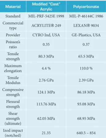
MATeRiAlS ChoiCeNowadays, most of civil and military aircraft windows are made with acrylic (PMMA) due to its transparency, availability, strength and ease maintenance, fulfilling all the aviation requirements and standards (Blass 1985; LaPluma and Bridenbaugh 1988). This material also meets the requirements for external surfaces of reinforced transparency. However, in case of violent impact, it can shatter, causing sudden aircraft depressurization. To satisfy the high impact strength requirement, the best polymer is PC, already used in military fighter aircraft canopies (Wiser 1971). Both materials have high light transmission levels and they are thermoformable. To connect these two materials, the aliphatic PU films (Plepis 1991; Vilar 1991) can be used, providing the adhesion between layers. Table 1 shows the properties of the chosen materials for the manufacture of aircraft observation window.
After materials selection, it was carried out a temperature resistance test to verify the laminate behavior at 100 °C.
Material Modiied “Cast”
Acrylic polycarbonate
Standard MIL-PRF-5425E 1998 MIL-P-46144C 1986 Commercial
type ACRYLITE® 249 LEXAN® 9034 Provider CYRO Ind, USA GE-Plastics, USA Poisson’s
ratio 0.35 0.37
Tensile
strength 80.3 MPa 65.5 MPa
Maximum
elongation 4.4 % 110.0 %
Tensile
Modulus 2.76 GPa 2.39 GPa
Compressive
strength 124.1 MPa 86.18 MPa
Flexural
strength 113.76 MPa 93.08 MPa
Shear strength (ultimate)
62.05 MPa 68.95 MPa
Izod impact
(notched) 21.35 640.5 – 854
Table 1. Acrylic and polycarbonate mechanical properties.
There was no appearance of undesirable bubbles, yellowing, delamination or any other conduct that could compromise the functions of the laminate or its general appearance. It was also verified that the temperature would not compromise the good light transmission without distortion or deformation.
ShApe DeTeRMinATion
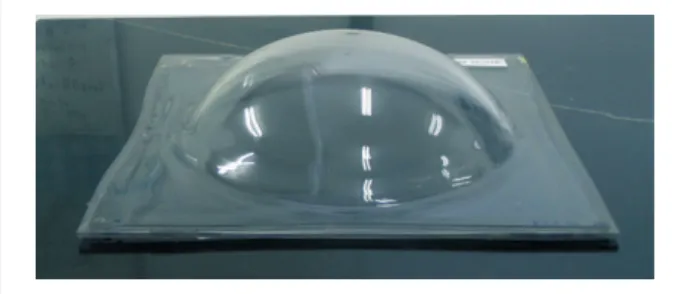
he inal shape of the transparency is better deined by the obtaining process than by a geometry deined through engineering software (Fig. 4). The method used to obtain the transparency form was the thermoforming by blowing compressed air (Blass 1985), since it allows the material to expand freely until the desired format is obtained.
opTiCAl DiSToRTionS
Samples submitted for veriication did not have relevant distortions, detected by the human eye, which could compromise the good appearance of the grid images captured through the transparence (Fig. 6). However, it was detected the presence of a slight optical power due to thickness variation at the center of the part, resulting from thinning, occurred during the thermoforming process, which creates a kind of diverging lenses. he contact with the thermoforming tool produces contact marks that are manifested in the form of distortion of the edge part; however, these distortions do not afect the results, when transparency is in use, since it does not become apparent because this region is covered by the transparency frame.
The optical distortions verification (Fixler 1977) is an important parameter in reinforced transparencies (Pardini and Peres 1996). he reinforced transparency, besides being considered a barrier to prevent an efort to continue, should allow observing or capturing images through it with the best possible quality, not adding deviations image distortions, retain the light wavelength or ilter visible spectrum.
All the images captured during the transparencies light test had an excellent clarity and no visible distortions, which conirmed the prior results obtained with the grid.
SheARing ReSulTS in plAne
Aircraft side windows have a significant temperature diferential between inner and outer layer, as much higher as the aircrat lying altitude. he internal temperature is usually around 20 °C, and the outer temperature can be less than −54 °C, so the dimensional variation between layers produces high big shear forces that must be compensated by the polyurethane layer elasticity. In this case, the PU adhesion between acrylic and/or polycarbonate must be veriied. he shear test indicates the degree of adhesion acquired by the laminated.
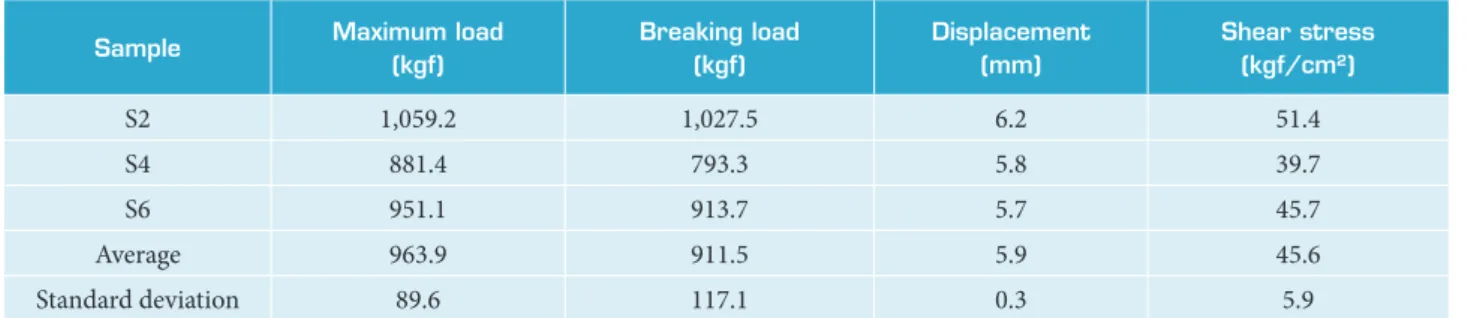
Each trial lasted until a little over 2 min, since the total displacement was around 6 mm. Tables 2 and 3 contain the results obtained in the shear test.
he test speed of 3 mm/min was appropriate, according to the behavior observed, which does not present a premature rupture and produces a clear “load × delection” curve. he standard deviation in general demonstrates a short range of values, or more reliability in the results obtained. he test speed of 5 mm/min does not produce results with small variation, since the values obtained were two or three times higher than the values obtained with test speed of 3 mm/min.
he maximum shear stress average demonstrates a satisfactory adhesion degree between layers in both speed tests and was greater than the expected.
A more detailed analysis of the displacement data between the sheets of acrylic and polycarbonate may provide an order of magnitude for the lengthening ability of the polyurethane adhesive, but the PU manufacturer (Huntsman, USA) indicates
B-B
B B
A A
A-A
L-B B
A L-A
H
Figure 4. Orthogonal views and transparency section. A-A: Height; B-B: Width; L-A: Vertical vision angle; L-B: Horizontal vision angle; H: Depth.
Figure 5. Laminated after thermoforming made with an appropriate tool.
Figure 7. Curve “load × delection” of the S2. mm
kg
f
0 0 120 240 360 480 600 720 840 960 1080
1 2 3 4 5 6 7 8 9 10 500% of elongation at the KRYSTALFLEX® PE399 datasheet (Huntsman 2015).
All samples tested were broken or showed detachment from plastic layers. The S2 had supported the major load, and S4, the minor one. Figure 7 shows a typical curve of “load × delection” generated by S2 test.
needed to design and to construct a reinforced transparency for an aerospace application, which is part of the “observation window” of a military patrol aircrat, as well as to validate such information through the construction of the transparency and analysis of the results.
he combination of the techniques used and the layers union in an appropriate and sequential manner was essential for the construction of transparency, which was successfully completed. Any failure would not allow the following step.
he optical results allow to state that the material choices were appropriate, especially on the composition and position of them. The acrylic usage on the internal and external faces of transparency had ensured the necessary optical quality. he fabrication process chosen, by the free expanding thermoforming, guaranteed a regular format of the visible area because there were no contacts with any tool.
All samples presented a satisfactory adhesion degree between layers during the shearing tests in plane. The parameters of speed test were greater than the expected, but this did not affect the results; the samples showed mechanical resistance parameters required by the aeronautical industry. Therefore, it was possible to demonstrate the technological knowledge necessary for the development and manufacture of reinforced aerospace transparencies for this type of application.
Sample Maximum load
(kgf)
Breaking load (kgf)
Displacement (mm)
Shear stress (kgf/cm²)
S2 1,059.2 1,027.5 6.2 51.4
S4 881.4 793.3 5.8 39.7
S6 951.1 913.7 5.7 45.7
Average 963.9 911.5 5.9 45.6
Standard deviation 89.6 117.1 0.3 5.9
Table 2. Results obtained in the shear test at the speed of 3 mm/min.
Sample Maximum load
(kgf)
Breaking load (kgf)
Displacement (mm)
Shear stress (kgf/cm²)
S1 1,010.2 982.7 6.2 49.1
S3 1,034.3 967.7 6.4 48.4
S5 972.8 896.7 6.3 44.8
Average 1,005.8 949.0 6.3 47.5
Standard deviation 31.0 45.9 0.1 2.3
Table 3. Results obtained in the shear test at the speed of 5 mm/min.
CONCLUSIONS
REFERENCES
Blass A (1985) Processamento de polímeros. Florianópolis: UFSC.
Fam A, Rizkalla S (2006) Structural performance of laminated and unlaminated tempered glass under monotonic transverse loading. Construct Build Mater 20(9):761-768. doi: 10.1016/ j.conbuildmat.2005.01.051
Fixler SZ (1977) Thermsstructural and material considerations in the design of the F-14 Aircraft Transparencies. J Aircraft, 14(3):257-264.
Fox DW, Christopher WF (1962) Polycarbonates. New York: Reinhold Publishing Corporation.
Huntsman (2015) KRYSTALFLEX® PE399 data sheet on line. [accessed 2015 Oct 15]. http://www.huntsman.com/polyurethanes
LaPluma PT, Bridenbaugh JC (1988) Speciications and measurement procedures for aircraft transparencies. Wright-Patterson AFB, OH: Armstrong Aerospace Medical Research Laboratory.
LeGrant DG, Bendler JT (2000) Handbook of polycarbonate science and technology. New York: Marcel Dekker.
Pardini LC, Peres RJC (1996) Tecnologia de fabricação de pré-impregnados para compósitos estruturais utilizados na indústria aeronáutica. Polímeros 6(2):32-42.
Plepis AMD (1991) Caracterização térmica e viscoelástica de resinas poliuretanas derivadas do óleo de mamona (Master’s thesis). São Paulo: Universidade de São Paulo.
Smith FC, Moloney LD, Matthews FL, Hodges J (1996) Fabrication of woven carbon ibre/polycarbonate repair patches. Compos Appl Sci Manuf 27(11):1089-1095. doi: 10.1016/1359-835X(96)00070-X
Vilar WD (1991) Química e tecnologia dos poliuretanos. 2nd ed. Rio de Janeiro: Vilar Consultoria Técnica Ltda.