Influence of Temperature and Time of Austempering Treatment on Mechanical
Properties of SAE 9254 Commercial Steel
J. A. Cruz Jr.1)*, T. F. M. Rodrigues1), V. D. C. Viana1), H. Abreu2), and D. B. Santos1)
1)Metallurgical and Materials Engineering Department, Federal University of Minas Gerais, Belo Horizonte, Brazil 2)Metallurgical and Materials Engineering Department, Federal University of Ceara´, Fortaleza, Brazil
* Corresponding author; e-mail: [email protected]
This work describes the steps in the study and development of the high content of C, Si, and Cr in commercial steel with a nanostructured matrix of martensite, bainite and retained austenite. Specimens of this steel were austenitized at 9008C for 5 min and isothermally heat treated at different times (0.5, 2, 24, 48 h) and temperatures (200, 220, 2708C). Different mechanical behavior was observed for the samples treated under different conditions due to their microstructural constitution. Specimens treated for 2 h at 2008C showed lower yield strength of 979 MPa. On the other hand a high tensile strength of 2248 MPa was reached. The sample treated at 2708C showed higher yield strength of 1363 MPa with the same treatment time. As for the fracture analysis, the brittle fracture mechanism was predominant for the samples treated at 2008C, while the ductile fracture mechanism was predominant for the samples treated at 2708C.
Keywords:bainitic ferrite, fracture mechanism, martensite, mechanical properties, retained austenite Submitted on 7 July 2011, accepted on 18 August 2011
Introduction
The production of carbide-free bainitic steel has increased in recent years with its introduction to the automotive industry [1, 2]. The microstructure of carbide-free bainitic steel consists of bainitic ferrite sheaves, carbon-enriched retained austenite and that may still contain martensite, resulting in an excellent combination of strength and toughness which is comparable to quenched and tempered martensitic steel. The retained austenite is present in two morphologies: thin films between bainitic ferrite subunits and blocks separating the sheaves. The first has a higher concentration of carbon, because the excess carbon in bainitic ferrite diffuses to austenite. Consequently the retained austenite films are more thermally and mechan-ically stable, [3, 4] while in the form of blocks and under the effects of stress and/or strain, transforms it into a hard brittle martensite, which contributes to lower toughness [5, 6].
The precipitation of cementite during bainite trans-formation can be avoided by the addition of 1.5 wt% Si which has a low solubility in cementite retarding its growth from austenite. The carbon rejected from cementite enriches the retained austenite causing the formation of the mixed microstructure described in the preceding paragraph. The absence of carbides results in a higher resistance to cleavage fracture and void formation [7–12].
It is believed that the ductility in these microstructures is controlled by the amount of retained austenite [13], which is its ductile phase. The presence of bainitic ferrite sheaves and martensite shows high toughness and strength. Young and Bhadeshia [14] showed that increasing the volume fraction of bainite in a microstructure containing martensite by 25% resulted in maximum yield strength.
Thus, this present study investigates the influence of different low heat treatment temperatures and times on the mechanical properties of SAE 9254 commercial steel in order to produce a carbide-free bainite, martensite and retained austenite nanostructure matrix. The SAE 9254 steel is used in the manufacturing of axels, coil springs and tools. It has a high content of C and Si but it does not have expensive alloy elements like Mo, Ni and Co which is used to obtain carbide free bainite [7–11].
Material and Experimental Procedure
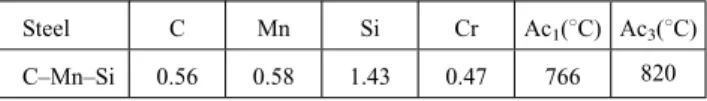
SAE 9254 steel is used in the manufacturing of axels, coil springs and tools. Its composition and transformation temperatures, Ac1 and Ac3, estimated by the empirical
formulas of Andrews [15] are listed in Table 1. The high concentration of Si is responsible for avoiding the carbides precipitation while the presence of Mn and Cr promote the hardenability and inhibits the formation of undesirable phases.
The steel was received in its hot rolled state and showed a microstructure of fine pearlite and some islands of pro-eutectoid ferrite (Fig. 1). The calculated volume fraction of pro-eutectoid ferrite was 0.06.
The tensile specimens with a 4 mm diameter and a 25 mm gauge length were austenitized at 9008C for 5 min prior to
isothermal heat treatments of 200, 220 and 2708C for
Table 1. Chemical composition in wt.%.
Steel C Mn Si Cr Ac1(8C) Ac3(8C)
different times – 0.5, 2, 24, 48 h – in order to obtain a microstructure with a mixture of bainite, martensite and retained austenite. The heat treatment was performed in an isothermal bath consisting of an alloy of Sn60-Pb40 that has a melting point below 2008C. The temperature was controlled by a type K thermocouple. Finally, the specimens were air cooled to room temperature (Fig. 2).
The temperatures used for the heat treatments were chosen in order to obtain a multiphase microstructure. Martensite (Ms) and bainite (Bs) transformation start temperatures were
respectively 594 and 2788C, calculated according to
equations (1) and (2) [16].
BsðCÞ ¼ 830270C90Mn
37Ni70Cr83Mo (1)
MsðCÞ ¼ 539423C30:4Mn
17:7Ni12:1Cr7:5Mo (2)
C, Mn, Cr, etc. are steel alloying elements (wt.%).
After the thermal cycles, the specimens were subjected to tensile testing in an Instron 5582 machine equipped with an extensometer of 10 mm. The tests were performed at room temperature with an equal strain rateð Þ ¼e_ 103s-1. From
the engineering stress-strain curves, the yield strength (YS) and tensile strength (TS) were obtained. The uniform strain (eu) was obtained from the true stress-strain curve. Strain hardening was characterized by the incremental strain-hardening exponent obtained from the plastic stress-strain curve, equation 3.
ni ¼ dðlnsÞ=dðlneÞ (3)
The microhardness tests were performed with a Future Tech hardness machine, using the Vickers indenter with a load of 0.3 kg and a loading time of 20 s; twenty measure-ments were performed along the diameter of the samples. The specimens for the Tecnai-G2-20-FEI (200 kV) trans-mission electron microscope were prepared in an unconven-tional manner, using a focus ion beam (FIB) coupled to the scanning electron microscope (SEM). Due to this destruc-tive technique, a thin film of Pt was deposited at the rectangular region of the sample with the dimensions of 102mm2, in a way that the cut around the area did not damage the surface. After the deposition of the film, a gallium (Gaþ) ion beam with a current ranging from 1 nA to 10 pA, and a voltage of 30 kV was focused around the selected area causing a 2 mm erosion depth to three of the four sides of the rectangle vicinity, as a result of this the sample remained suspended on one of the rectangle sides. Finally, the sample was thinned to a thickness of 100 nm.
Scanning electron microscopy (SEM) performed the fracture surface analysis. Optical microscopy was also used to verify the fracture mechanism in the cross section normal to fracture surface.
The retained austenite volume fraction was quantified by X-ray diffraction using the direct comparison method. This method uses the integration of the most intensive austenite peaks, characterized by the planes (111), (200), (211) and (220). After grinding and polishing using diamond paste of 3mm, the analysis was performed on a Philips PW 1710 diffractometer using Cu Karadiation at a rate of 0.028/min,
voltage of 40 kV and current of 20 mA. The X-ray data diffraction was also used to determine the carbon concen-tration in retained austenite according to equation 4.
ag ¼ 3:578 þ0:033%Cg (4)
Cg is the carbon concentration of retained austenite in
wt.% and agis its lattice parameter in A˚ [17, 18].
The metallographic specimen was then polished using colloidal silica for 30 minutes, and the EBSD measurements were calculated on a SEM working with a tungsten filament electron gun operating at an acceleration voltage of 20 kV. The EBSD packets used in this examination were a Channel 5 HKL technology, using a Nordlys II digital EBSD camera. The EBSD orientation cartography acquired a step size of 100 nm and by assuming the presence of two possible crystallographic phases: Fe-FCC for austenite and Fe-BCC
Figure 1. SEM micrograph of the hot rolled steel etched with 2% Nital.
for ferrite, which is indeed mostly bainite (regions contain-ing martensite were also indexed as BCC but they were associated with a low quality index of the diffraction patterns and can be distinguished from bainite).
The EBSD data was post-processed by the HKL CHANNEL 5 Tango software to obtain the microstructure information. The Oxford Channel 5 EBSD software has a tool called the Band Contrast or Band Slope which makes it possible to assign lower pixel values to martensite and bainite. Since each phase tended to have different BC value averages (this will be discussed in the discussion section) phase separation was attempted by using the BC parameter. The distribution histogram of the misorientation angle corresponding to this last selection is directly calculated by the software for all its pairs of neighboring pixels. The low misorientations of the angles are corresponded to adjacent pixels belonging to the same phase and are not taken into account in the analysis [19–21].
Results and Discussion
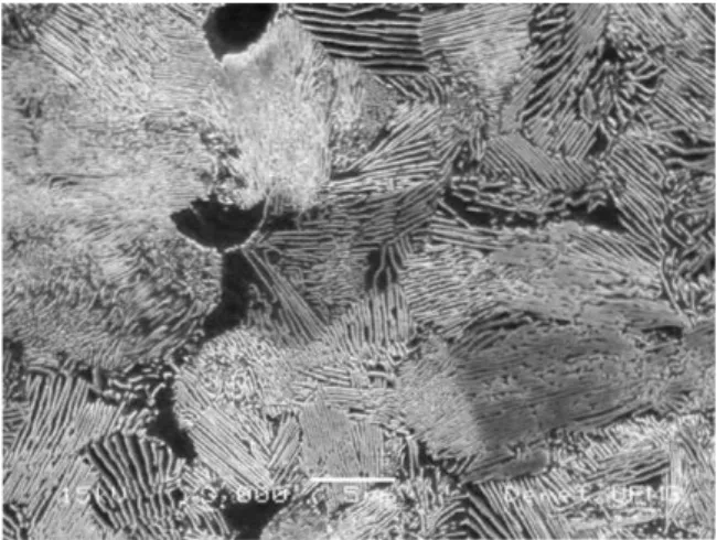
Microstructural characterization. Bainitic ferrite sheaves, retained austenite films and martensite were observed in the TEM micrograph shown in Fig. 3. It is observed that the bainitic ferrite sheaves with a 200 nm thickness or less are separated from the retained austenite films. The increase in toughness and the ultimate tensile strength is attributed to the microstructure narrow thickness [22]. This is the result from the increased austenite resistance at low temperatures and increased free energy variations in the transformation [23].
The maximum amount of bainite that can be obtained at any temperature is limited by the fact that the carbon content of the residual austenite reaches the T00curve of the phase
diagram. At this point, the carbon-enriched austenite does
not transform into bainite any further ðDGg!a¼0Þ [24].
The T0curve is the locus of all points, on a temperature
versus carbon concentration plot, where austenite and ferrite of the same chemical composition have the same free energy. The T00curve is defined similarly but takes into
account the stored energy of the bainitic ferrite due to the displacive mechanism transformation of 400 J/mol [25].
The carbon concentrations of the retained austenite for the samples isothermally treated at different temperatures and times are shown in Fig. 4(a). Figure 4(a) presents the theoretical values calculated for T0
0, T0and Ae3[26]. X-ray
diffraction analyses were also used to calculate the amount of retained austenite present in the microstructure according to their treatment times and temperatures which the results are shown in Fig. 4(b). The retained austenite volume fraction is generally higher when the processing occurs at higher temperatures; as a result a smaller amount of martensite is formed. It is also possible to note that the retained austenite volume fraction decreases with the isothermal transformation time for all heat treatment temperatures. This occurs because a greater amount of bainitic ferrite is formed during the isothermal treatment [27]. In addition, for the sample treated at 2008C for 0.5 h there is a smaller amount of retained austenite, since the treatment time was insufficient for the carbon-enriched austenite to reach its stability, therefore martensite can be formed during the final cooling down to room temperature. The presence of high Si content in medium grade carbon steel prevents the formation of carbides during air cooling allowing the formation of retained austenite in the final microstructure [28]. The Band Contrast tool makes it
possible to assign lower pixel values to martensite and bainite. This is very useful in the study of the orientation relationship between the displacive phases and the austenite. It is very easy for the EBSD technique to differentiate the
retained austenite from the bainite or martensite since austenite is classed as FCC, bainite and martensite are classed as BCC or BCT. However, differentiating the bainite and martensite from ferrite with EBSD is very difficult. In the present steel, the relation c/a for martensite is 1.03 being almost impossible to differentiate bainite from martensite by EBSD with a standard SEM [29]. The dislocation density of martensite is higher than bainite and higher than ferrite. The regions with higher dislocation densities show worse image quality.
Fig. 5(a)shows the band contrast map for one measured region and Fig. 5(b) shows the distribution of band slope values. This sample was austempered at 2708C for 0.5 h. The band slope values vary from 32 to 120. These values are similar to those obtained by Ryde [19] for a microstructure of ferrite, bainite and martensite. For this study it will be assumed that the band slope values above 80 correspond to bainite and any below this value will correspond to martensite.
Fig. 6shows the band contrast map with a total of 3.7% of retained austenite painted in green. This value was
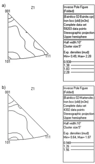
underestimated when compared to the X-ray measurements. The austenite clearly appeared as a film, as well as a blocky morphology between bainitic ferrite.Fig. 7(a) and(b)are band contrast maps with band slopes above 80 (bainite) and below 80 (martensite).Fig. 8(a)and(b)show the orientation of both the bainite and martensite. They are inverse pole figures for the cross section plan of the sample. For both phases the most intense texture component is [001]. The position of misorientation axes is close to the ideal orientation relationships of Kurdmov-Sachs and Nishiama-Wasserman [20].
Mechanical properties. Fig. 9shows the stress-strain curves and the variation of strain hardening exponent nias a
function of true strain after processing at 2008C for different
heat treatment times. For this temperature a larger amount of
a)
b)
Figure 4. Comparison of experimental and calculated dataT0
0, Ae3. The vertical line (X) represents the carbon molar fraction in the steel (a); volume fraction of retained austenite as a function of time and temper-ature of the isothermal transformation (b).
martensite is formed during the initial cooling from austenitizing temperature (Fig. 2).
According to Fig. 9(a) the yield strength is greater than 900 MPa and the tensile strength is ranging from 1990 to 2250 MPa. It is observed that the stress strain curves for the specimens isothermally treated for 0.5 and 2 h showed similar behaviors. However, a higher total elongation and tensile strength was reached for the specimens heat treated for 2 h. This is due to the retained austenite blocks
Figure 6. The band contrast with FCC phase in green. This sample was austempered at 2708C for 0.5 h.
Figure 8. The inverse pole figures for bainite (a) and martensite (b) from the sample in Fig. 7.
morphology transformation into martensite by the TRIP effect during tensile test, which provides greater strength and total elongation. Evidence of the TRIP effect can be observed in Fig. 9(a) for the specimens isothermally treated by 0.5 and 2 h. This is because during the tensile test the blocks of retained austenite transform into hard, brittle and non-tempered martensite. This martensite thus contributes to the rupture of the specimens before the onset of necking [13]. Another evidence for ocurrence of the TRIP effect is the larger incremental work hardening, resulting in the increase of uniform elongation (Fig. 9(b)) and the tensile strength (Fig. 9(a)) [30, 31].
The specimens treated for 0.5 and 2 h showed lower yield strength compared to the specimens treated for 24 and 48 h due to the fact that the deformation first occurs in the blocks of the retained austenite (soft phase). The martensite (hard phase) only begins to deform when the strain hardening point of the austenite is high enough that the applied stress is able to start the deformation in the martensite [32].
The high strain hardening exponents achieved for the specimens treated for 0.5 and 2 h were associated with the transformation of the retained austenite blocks into
martensite during the deformation. This high strain harden-ing exponent for a small plastic deformation is characteristic to all dual-phase steel, according to the work of Krauss and Matlock [33, 34]. On the contrary, the curves of the strain hardening exponent for the specimens treated for 24 and 48 h show a lower value, due to the presence of retained austenite films imbedded among the bainitic ferrite sheaves, which are more mechanically stable, and strain hardening occurs before reaching its tensile strength value, Fig. 9(a) [35].
For the transformation at 2208C, a low amount of
martensite was formed at the beginning of isothermal heat treatment, thereby reflecting on the final amounts of the constituents and consequently on the mechanical properties of the specimens (Fig. 10).
According to Fig. 10, a good combination of the mechanical properties was achieved for the specimens heat treated for 2 h – 1256 MPa (YS), 2000 MPa (TS) and 5.5% (EL). It also can be noted that there is a lower difference in the yield strength for the samples isothermally treated for 0.5 and 2 h to those treated for 24 and 48 h. This occurs because the amount bainitic ferrite increases as well with the treatment time. A lower strain hardening exponent for specimens treated for 24 and 48 h compared to the specimens
a)
b)
Figure 9. (a) shows the engineering stress-strain curves while (b) shows the incremental work hardening curvesniobtained from the transformation at 2008C for different heat treatment times.
a)
b)
treated for 0.5 and 2 h (Fig. 9(b) and Fig. 10(b) was observed. This condition is associated with the higher mechanical stability of the retained austenite films.
The results shown in Fig. 11correspond to the highest temperature used in this study. In this case the lowest initial amount of martensite was formed when compared with the other two temperatures. Therefore, a greater amount of residual austenite is present to decompose into bainite during the isothermal treatment time. An important arrange-ment of mechanical properties was observed for the specimens treated for 0.5 h – 1273 MPa (YS), 1729 MPa (TS) and 4.2% (EL). The observation noticed is that the behavior of the strain hardening exponent is very similar, differing only for the specimen treated for 0.5 h. The hypothesis is that this isothermal treatment time was not sufficient enough for the bainitic transformation. Thus the presence of a great number of retained austenite blocks was responsible for the increase in the strain hardening exponent (Fig. 11(b)).
Comparison of mechanical properties. The results of the yield and tensile strength are show inFig. 12 (a)and(b).
According to Fig. 12(a), for the three temperatures used in this study the heat treatments of 0.5 and 2 h resulted in lower yield strength probably due to the greater amount of bainitic ferrite sheaves [27]. According to Miihkinen and Edmonds [36] the decrease in yield strength is associated with the increased amount of retained austenite. However, the tensile strength is less sensitive to the amount of retained austenite among the bainite sheaves.
The specimens treated at 200 and 2208C showed a higher
increase in yield strength for times of 24 and 48 h. These periods of heat treatment produce an important mixture of martensite and bainitic ferrite sheaves formed [14].
In Fig. 12(b) it is observed that the tensile strength almost does not change with the heat treatment time and its value increases while the temperature deceases. This occurs because the amount of martensite formed at the initial cooling is greater according to Fig. 2, thus providing an increase in tensile strength [37–39].
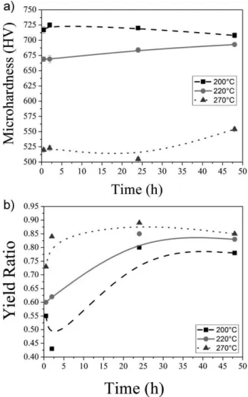
Fig. 13(a)shows that the lowest transformation temper-ature resulted in the highest microhardness. It is also observed that there was a small variation in the microhard-ness as a function of isothermal treatment time. This is
a)
b)
Figure 11.Shown are the engineering stress-strain curves (a) of the incremental work hardeningniobtained after transformation at 2708C for different heat treatment times (b).
associated with the difference in the amounts of the constituents formed during the isothermal treatment. High values of hardness result from the martensite and on the contrary low values reflect the influence of the bainite and retained austenite.
The yield ratio (YS/TS) is shown in Fig. 13(b). This parameter can be used to the evaluation of the strain hardening behavior [38]. As yield ratio decreases the strain hardening rate increases. This happens for short times and lower temperature of transformation, Figs. Fig. 9(b) – Fig. 11(b) and Fig. 13(b). The volume fraction of the martensite is playing an important role in this behavior due to the generation of mobile dislocations in the ferrite neighboring the martensite islands [39].
The isothermal heat treatments of 0.5 and 2 h showed the smallest values of yield ratio for the low temperatures of 200 and 2208C. It is stated in literature that the lower value of
yield ratio is due to the large amounts of retained austenite blocks in the microstructure [8, 13]. The largest volume fraction of the retained austenite in the microstructure can be accounted for the increase in the strain hardening rate.
However, it can be observed that the higher the time and temperature of the isothermal treatment the higher the yield ratio. The increase in treatment time provides a major transformation of residual austenite into bainite. The microstructure, as described before, is composed of bainitic ferrite sheaves interspersed with films of retained austenite. The increase of the bainite phase amount increases yield strength, and consequently, the yield ratio (YS/TS). Once again, the highest transformation temperature decreases the onset time of the transformation, providing a larger amount of bainitic ferrite and retained austenite films and con-sequently higher values of yield ratio for the lowest time of treatment.
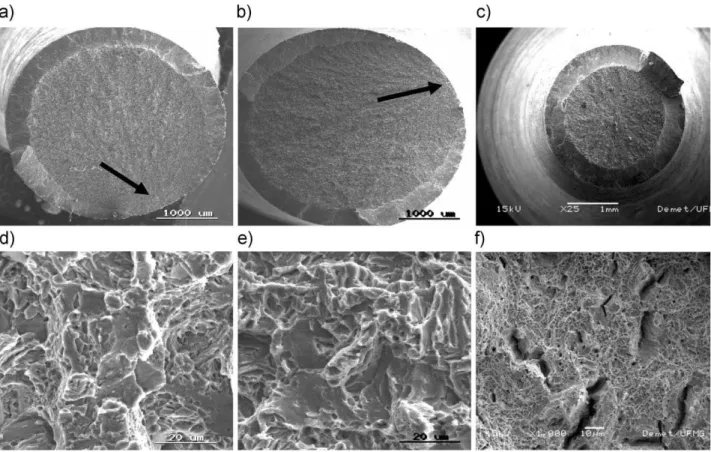
Fracture surface analysis. The mechanical properties obtained from tensile tests result from the balance among constituents present in the microstructure - bainite, retained austenite and martensite. These constituents, in turn, allow an interpretation of the fracture mechanism that operates during the tensile test.Fig. 14(a-f)shows the fracture surface of specimens isothermally treated at 2008C, 2208C and 2708C for 48 h.
Fig. 14(a) shows a fracture surface characterized by a brittle appearance which exhibits some ductility during tensile test, some microvoids can also be identified easily although there is a mixture of fracture mechanisms. The brittle fracture is dominant resulting in the large amount of martensite formed at the initial cooling.
In a recent study carried out by Saeidi and Ekrami [40] on dual-phase ferrite-martensite steel and ferrite-bainite AISI 4340 which the volume fraction of ferrite was established at 34% Vv, the results showed a mixture of fracture mechanisms during deformation operating simultaneously. In the case of dual-phase ferrite/martensite steel, there is a mixture of dimples and cleavage regions that characterize the ductile and brittle fracture, respectively. This fracture has been called quasi-cleavage. On the other side, for dual-phase ferrite/bainite steel, the ductile fracture mechanism is predominant. Fig. 14(e) shows a mixture of both fracture mechanisms, part is quasi-cleavage and part must be intergranular. Microvoids can be easily identified which is associated with some ductility during tensile test (Fig. 10(a)).
An important characteristic of the brittle fracture surface are the radial marks. These marks extend across the fracture surface nearly up to the free surface, where shear lips are formed at approximately 458to normal direction of
tensile stress [41]. When the fracture is nucleated on the sample surface, the initiation of the fracture region does not show shear lip (the arrows in Figs. 14(a) and (b)).
Fig. 14(c) and (f) characterize a ductile fracture, despite containing some brittle regions. Regions containing cracks can also be observed. When the fracture has only fibrous regions and a shear lip this is known as cup-cone, as is the case in Fig. 14(c). Tomita and Okabayashi [42] have also studied dual-phase (AISI 4340) bainite/martensite steel and found that the origin of the cracks were in the vicinity of the bainite and martensite’s interface. This is due to the high
local internal stress initiated in the vicinity of the two phases of interface as a result of non-uniform strain. The same behavior was observed by Caballeroet al. [43],
whose results showed that the boundary between the martensite plates and the bainite matrix is the micro-structural feature responsible for the crack nucleation.
Fig. 15(a and b) shows the optical micrographs of the cross-section and its nearby fractured surface for the specimens isothermally treated at 200 and 2708C for
2 and 0.5 h.
In Fig. 15(a) the crack path appears in a zigzag and branching direction which is typical to an intergranular brittle fracture. This morphology is associated with a complex microstructure formed by bainitic ferrite sheaves interspersed with retained austenite films. Blocked austenite and martensite are the last mostly likely to be present in this phase of the isothermal treatment. Classical literature [16, 24] has shown that the blunting of the crack occurs at the bainite lath package and at the retained austenite films. The plastic deformation of the retained austenite films
Figure 14.The fracture surfaces of specimens isothermally treated at three different temperatures for 48 h.
present themselves between the bainitic ferrite sheaves and martensite. A smooth stress concentration on the crack tip which consumes the energy during its propagation; there-fore, increases the resistance to crack propagation and decreases its propagation rate. According to Xuet al.[44]
due to the large angle boundary of the martensite plate packet boundary of the neighboring bainite plate which reduces the effective grain size as a fatigue fracture unit. It leads to the change in crack orientation and crack branching, so more energy could be absorbed along the crack path (Fig. 15(a)). Although small in elongation there is a high strength associated with the high work hardening exponent in reference to Fig. 9(a) and (b). In Fig. 15(b) the specimen treated at 2708C for 0.5 h the microstructure is composed
mainly of bainitic ferrite sheaves interspersed with retained austenite films. There is a single crack with only non branching single direction of propagation. It characteristic to a transgranular fracture due to microvoids coalescence [41].
Conclusions
The SAE 9254 steel was isothermally heat treated at different temperatures and times. From the results of the experiments it can be concluded that:
1. It was observed that for the specimens treated for 2 h at 2008C and for 0.5 h at 2708C a multiphase microstructure
was formed by bainitic ferrite sheaves interspersing with retained austenite films and martensite.
2. A pronounced TRIP effect was also noted for the specimens heat treated at 2008C for 0.5 and 2 h due to
a greater number of retained austenite blocks.
3. By increasing the isothermal treatment temperature for times of 0.5 and 2 h it can also be observed that yield strength increases (YS) which is due to the increased amount of bainitic ferrite.
4. The lower the isothermal treatment temperature the higher the tensile strength is again due to the increase in the amount of the martensite formed at the initial cooling. 5. For the specimens heat treated for 2 h at 2008C a brittle
fracture was the predominant mechanism with intergra-nular crack propagation. For the specimens heat treated for 0.5 h at 2708C a ductile fracture mechanism with
transgranular crack propagation was observed which resulted from microvoid coalescence.
Acknowledgements
This study was supported by FAPEMIG, State Foundation for Research Development of Minas Gerais, and CNPq, National Council for Technological and Research Development. Thanks also to Centro de Microscopia Eletroˆnica – UFMG for TEM micrographs.
References
[1] H. A. Aglan, Z. Y. Liu, M. F. Hassan, M. Fateh: J. Mater. Proc. Technol.151 (2004) 268–274.
[2] K. Sawley, J. Kristan: Fatigue Fract. Eng. Mater. Struct.26 (2003) 1019–1029.
[3] H. K. D. H. Bhadeshia, D. V. Edmonds: Metall. Trans.10A (1979) 895–907.
[4] H. K. D. H. Bhadeshia, D. V. Edmonds: Met. Sci.17 (1983) 420–425.
[5] C. Garcia-Mateo, F. G. Caballero, J. Chao, C. Capdevila, C. Garcı´a de Andre´s: J. Mater. Sci.44 (2009) 4617–4624.
[6] F. G. Caballero, C. Garcia-Mateo, J. Chao, C. Capdevila, M. J. Santofimia, C. Garcı´a de Andre´s: ISIJ Int.48 (2008) 1256–1262.
[7] F. G. Caballero, H. K. D. H. Bhadeshia, K. J. A. Mawella, D. G. Jones, P. Brown: Mat. Sci. Technol.17 (2001) 512–516.
[8] F. G. Caballero, H. K. D. H. Bhadeshia, K. J. A. Mawella, D. G. Jones, P. Brown: Mat. Sci. Tech.17 (2001) 517–522.
[9] F. G. Caballero, M. J. Santofimia, C. Capdevila, C. Garcı´a-Mateo, C. Garcı´a de Andre´s: ISIJ Int.46 (2006) 1479–1488.
[10] S. J. Matas, R. F. Hehemann: Trans. Met. Soc. AIME221 (1961) 179– 185.
[11] R. F. Hehemann: Phase Transformations, American Society for Metals, Metals Park, OH, 1970. 121–153 pp.
[12] R. Lehouillier, G. Begin, A. Dube´: Metall. Trans.2A (1971) 2645– 2653.
[13] B. P. J. Sandvik, H. P. Nevalainen: Met. Tech.8 (1981) 213–220.
[14] C. H. Young, H. K. D. H. Bhadeshia: Mater. Sci. Tech.10 (1994) 209–214.
[15] K. W. Andrews: J. Iron Steel Inst.203 (1965) 721–727.
[16] R. W. K. Honeycombe, H. K. D. H. Bhadeshia: Steels Microstructure and Properties, 3rded. London: Gray Publishing, 1995. 95–154 pp.
[17] B. D. Cullity, S. R. Stock: Elements of X-ray Diffraction, 3rdEd. Addison-Wesley Publishing Co., Inc., New York, 2001. 349–361 pp. [18] D. J. Dyson, B. Holmes: J. Iron Steel Inst.208 (1970) 469–474.
[19] L. Ryde: Mat. Sci. and Tech.Vol. 22, N. 11, (2006) 11297–1306.
[20] C. Cabus, H. Regle´, B. Bracroix: Mater. Charac.Vol. 58, (2007) 332– 338.
[21] E. P. Kwon, S. F. Fujieda, K. Shinoda, S. Suzuki: Mat. Sc. Eng. A, Vol. 528, (2011) 5007–5017.
[22] F. G. Caballero, H. K. D. H. Bhadeshia: Curr. Opin. Solid State Mater. Sci.8 (2004) 251–257.
[23] S. B. Singh, H. K. D. H. Bhadeshia: Mat. Sci. Eng. A.245 (1998) 72– 79.
[24] H. K. D. H. Bhadeshia: Bainite in Steels, 2nded. London: IOM
Communications Ltd, 2001. 6–12 pp.
[25] H. K. D. H. Bhadeshia: Acta Met.29 (1981) 1117–1130.
[26] Materials Algorithms Project (MAP), University of Cambridge: http://www.msm.cam.ac.uk/map/steel/programs/mucg46-b.html. [27] N. V. Luzginova, L. Zhao, J. Sietsma: Mat. Sci. Eng. A.481–482
(2008) 766–769.
[28] C. P. Luo, G. C. Weatherly, Liu. Zheng-Yi: Met. Mat. Trans. A, Vol. 23 N. 5, (1992) 1403–1411.
[29] EBSD image homepage, www.ebsdimage.org/documentation/ qualitymetrics.htm#Ryde2006.
[30] O. Matsumura, Y. Sakuma, H. Takechi: Scr. Metall.21 (1987) 1301– 1306.
[31] K. Sugimoto, M. Tsunezawa, T. Hojo, S. Ikeda: ISIJ Int.44 (2004) 1608–1614.
[32] H. K. D. H. Bhadeshia: Ironmaking and Steelmaking.34 (2007) 194– 199.
[33] D. K. Matlock, G. Krauss: Strain Hardening of Dual-Phase Steels: An Evaluation of the Importance of Processing History, ASM, Ohio, 1984. 47–87 pp.
[34] G. Krauss, D. K. Matlock: J. Phys. III.5 (1995) 51–60.
[35] J. Chiang, B. Lawrence, J. D. Boyd, A. K. Pilkey: Mat. Sci. Eng. A.
A528 (2011) 4516–4521.
[36] V. T. T. Miihkinen, D. V. Edmonds: Mat. Sci. Tech.3 (1987) 432–440.
[37] R. G. Davies: Metall. Trans.9A (1978) 671–678.
[38] D. Das, P. P. Chattopadhyay: J. Mat. Sc.(2009) 2957–2965.
[39] A. S. Podder, D. Bhattacharjee, R. K. Ray: ISIJ Int.(2007) 1058– 1064.
[40] N. Saeidi, A. Ekrami: Mat. Sci. Eng. A523 (2009) 125–129.
[41] G. E. Dieter: Mechanical Metallurgy, SI Metric Edition, London, McGraw-Hill, 1988, 262–265 pp.
[42] Y. Tomita, K. Okabayashi: Met. Trans.16A, (1985) 73–82.
[43] F. G. Caballero, J. Chao, J. Cornide, C. Garcı´a-Mateo, M. J. Santofimia, C. Capdevila: Mat. Sci. Eng. A525, (2009) 87–95.