A
rti
c
le
0103 - 5053 $6.00+0.00
*e-mail: [email protected]
Nanostructured Thin Films Obtained by Electrodeposition over a Colloidal Crystal Template:
Applications in Electrochemical Devices
Vinicius R. Gonçales,a Mariana P. Massafera,a Tânia M. Benedetti,a David G. Moore,b
Susana I. Córdoba de Torresi*,a and Roberto M. Torresia
a Instituto de Química, Universidade de São Paulo, CP 26077, 05513-970 São Paulo-SP, Brazil
bMaterials Science and Engineering, University of Florida, P.O. Box 116400, Gainesville, Florida, USA
Partículas coloidais têm sido empregadas na síntese dirigida por molde de diversos materiais, tais como semicondutores, metais e ligas. Esse método permite um controle da espessura do material resultante através da escolha adequada da carga aplicada no sistema e é possível produzir materiais densamente depositados, sem rachaduras. Esses materiais são fidedignos à estrutura do molde e, devido às amplas áreas superficiais obtidas, são muito interessantes em aplicações eletroquímicas. Neste trabalho, a distribuição de um molde de poliestireno monodisperso foi realizada sobre substratos de ouro, platina e carbono vítreo com o intuito de exemplificar a eletrodeposição de um óxido, um polímero condutor e um material híbrido orgânico-inorgânico, com aplicações em supercapacitores e sensores. Os desempenhos dos eletrodos nanoestruturados foram comparados com os análogos massivos e os resultados obtidos são descritos.
Colloidal particles have been used to template the electrosynthesis of several materials, such as semiconductors, metals and alloys. The method allows good control over the thickness of the resulting material by choosing the appropriate charge applied to the system, and it is able to produce high density deposited materials without shrinkage. These materials are a true model of the template structure and, due to the high surface areas obtained, are very promising for use in electrochemical applications. In the present work, the assembly of monodisperse polystyrene templates was conduced over gold, platinum and glassy carbon substrates in order to show the electrodeposition of an oxide, a conducting polymer and a hybrid inorganic-organic material with applications in the supercapacitor and sensor fields. The performances of the resulting nanostructured films have been compared with the analogue bulk material and the results achieved are depicted in this paper.
Keywords: colloidal particle templates, polystyrene, macroporous materials, sensors, supercapacitors
Introduction
Three dimensional close packed arrays of monodisperse polystyrene or silica particles have attracted attention because of their potential to template synthesis of various materials.1 These spherical colloidal particles can be either synthesized2 or commercially acquired in a range of diameters from few nanometers up to micrometer scale.
Much of the interest in applying colloidal particles to template material synthesis has come from studies in photonic crystals,3 and the first reported electrodeposition through colloidal templates concerned the synthesis of
macroporous CdS and CdSe films for photonic bandgap studies.4 Later papers have used colloidal particles to electrodeposit ordered macroporous films of other semiconductors,5 metals,6,7 alloys,8 oxides9 and conducting polymers.10-12
by controlling the charge applied to the system.13 It is also important to comment that the first layer of templated material, grown to a thickness comparable to the diameter of the spheres used, has a structure which is different from the next layers. Consequently, surface topography can be modulated in a regular way by controlling the deposition bath and conditions.14
In this paper, the assembly of colloidal particle over glassy carbon, platinum and gold substrates is described. In order to show the versatility of this method, different substrates were used to electrodeposit an oxide, a conducting polymer and a hybrid inorganic-organic material with applications in different electrochemical devices, such as sensors and supercapacitors.
Experimental
Reagents
Pyrrole (Sigma-Aldrich, 99%) was purified by distillation and kept in the refrigerator under a N2 atmosphere, protected from light. Dodecylbenzenesulfonate (DBSA) (Aldrich), NaOH, H3BO3, acetone, KCl, NaCl, K3Fe(CN)6 (Synth, analytical grade), NH4Cl (Mallinckrodt, analytical grade), HCl (Quimex), CuCl2·2H2O (Cromoline), toluene (Maia), Triton X-100 (tetra-octylphenoxypolyethoxyethanol), 10 wt.% aqueous dispersion of monodisperse polystyrene spheres (460 nm diameter), lithium perchlorate, potassium permanganate (Aldrich), H2O2 (30 wt.% aqueous solution) and 8.0 wt.% aqueous solution of hydrogen hexachloroplatinate (IV) (Sigma-Aldrich) were all used as received.
All solutions were prepared using 18 Mohm cm water purified by an Elga UHQ system.
Instrumental
Electrochemical data were obtained with a Autolab model PGSTAT 30 potentiostat/galvanostat (Eco Chemie) interfaced with a computer for data acquisition. Atomic force microscopy (AFM) topographic images were obtained using a PicoSPM-LE Molecular Imaging System with cantilevers operating in the intermittent-contact mode (AAC mode), slightly below their resonance frequency of approximately 305 kHz in air. A field emission scanning electron microscope (FESEM, JSM-7401F from JEOL) was employed to study the morphology of the materials. For the electrochemical quartz crystal microbalance (EQCM) experiments, a 6.0 MHz AT-cut piezoelectric quartz crystal (Valpey – Fischer) with 25 mm diameter and 0.32 cm2 piezoactive electrode area (integral sensitive factor
6.45 × 107 cm2 Hz g-1) was employed. Frequency shifts were measured by using a Stanford Research System model SR620 instrument connected to an oscillating circuit.
Assembly of the polystyrene spheres
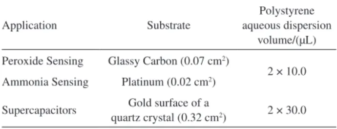
Polystyrene spheres were deposited over the substrates by adding a defined volume of a 0.5 wt.% aqueous polystyrene suspension containing 1.0 × 10⁻⁶ mol L-1 Triton X-100. The suspension was previously sonicated for 2 min in an ultrasound bath before assembly. The sample was left undisturbed in a saturated humidity chamber to allow water evaporation. After this process, another suspension aliquot of the same volume was deposited over the substrates and they were left in the saturated humidity chamber once more. After water evaporation, the electrodes were placed in an oven at 100 oC for 4 h. Depending on the application, the polystyrene suspension volume deposited was different, as well as the substrate, as summarized in Table 1.
Film electrodeposition
Macroporous CuHCNFe/PPy
A 3 mm diameter glassy carbon electrode was used as working electrode. Before the experiments, the electrode was sonicated in acetone for 5 min and in deionized water for other 5 min. Then the electrode was polished with successive slurries of 1, 0.3 and 0.05 µm alumina and sonicated for 5 min more in purified water. To remove polishing contaminants, 1.8 V was applied in the glassy carbon electrode, for 10 s, in a solution containing 0.1 mol L-1 NaOH.15 All the potentials are referred to a Ag/AgCl/Cl−
(sat) electrode, while a platinum foil was employed as the counter electrode.
Nanostructured copper hexacyanoferrate/polypyrrole (CuHCNFe/PPy) hybrid material was synthesized in a two-step electrochemical procedure described in a previous publication.16 First, the ferricyanide was incorporated in a polypyrrole matrix by cycling the electrode potential in a solution containing 0.02 mol L-1 K
3Fe(CN)6, 0.015 mol L -1 pyrrole and 0.1 mol L-1 KCl. It is very important to point
Table 1. Total volumes of polystyrene aqueous dispersion deposited over different substrates
Application Substrate
Polystyrene aqueous dispersion
volume/(µL)
Peroxide Sensing Glassy Carbon (0.07 cm2)
2 × 10.0 Ammonia Sensing Platinum (0.02 cm2)
Supercapacitors Gold surface of a
out that, before deposition, the electrode was kept inside the solution for 30 min, in order to assure the swelling of the voids between the polystyrene particles. After this time, the system was cycled 10 times in a potential range of – 0.25 V to + 0.95 V at 0.05 V s-1. The modified electrode was then placed in a solution containing 0.02 mol L-1 CuCl2and 0.01 mol L-1 KCl for 2 h, in order to allow the insertion of Cu2+ ions into the ferricyanide-doped polypyrrole matrix. Subsequently, the electrode potential was cycled 20 times in the same solution in a potential range of – 0.25 V to + 0.95 V at 0.05 V s-1.
After the deposition step, the polystyrene template was removed by soaking the electrode in toluene for 24 h, under stirring. Later, the modified electrode was washed and kept overnight in a desiccator.
Macroporous polypyrrole
Pyrrole polymerization over a Pt electrode (0.02 cm2) was performed potentiostatically at 0.7 V vs. Ag/AgCl from an aqueous solution containing 50 mmol L-1 monomer and 25 mmol L-1 DBSA, in a three electrode conventional cell using a Pt foil as auxiliary electrode. The amount of polypyrrole deposited can be controlled by choosing proper deposition times, in order to obtain charge densities of PPy in the range 0.10-0.50 C cm-2. To prepare bulk PPy films, pyrrole electropolymerization was performed directly over the bare Pt electrode, while to form nanostructured PPy the polymerization was performed after the template deposition, over the Pt electrode, as described earlier. After polymerization, electrode was kept in toluene for 24 h, under stirring, to dissolve the template. The thickness of the nanostructured electrodes was determined by scanning electron microscopy, by analyzing cross-section images. Average thicknesses were in the range: 1.3 to 2.0 µm. The so-called bulk sensors were also kept in toluene in the same conditions, to be sure that the different effects observed when comparing bulk and nano sensors are only due to the nano-features.
Macroporous MnO
2
Manganese dioxide films were galvanostatically electrodeposited from 0.02 mol L-1 KMnO
4 aqueous solution over electrodes containing deposited polystyrene nanospheres. Before the electrodeposition process, the electrode was maintained immersed in permanganate solution for 45 min. As the applied charge must not be too high in order to avoid deposition above the nanospheres, covering all of them, a 240 µA cathodic current was applied for different times and the ideal electrodeposition time was determined by analyzing the scanning electron microscopy (FESEM) images obtained from the electrodeposited
films. The electrodeposition process was monitored by a electrochemical quartz crystal microbalance (EQCM) in order to obtain the mass of deposited material.
After electrodeposition, the electrode was maintained immersed for 3 h in tetrahydrofuran under stirring, in order to remove the polystyrene spheres, and dried under vacuum at 45 oC for 12 h.
Electrochemical measurements
Hydrogen peroxide detection
The macroporous CuHCNFe/Ppy film was applied for H2O2 detection in a 0.1 mol L-1 NaCl + 0.1 mol L-1 HCl stirred electrolytic solution. At first, the modified electrode was held at 0.0 V for 30 min to stabilize the background current. Then, 10 µL of a 50 mmol L-1 H
2O2 solution were successively added to obtain the chronoamperograms. Each H2O2 addition corresponded to a 0.1 mmol L-1 increment in the analyte concentration.
Ammonia detection
T h e c h r o n o a m p e r o m e t r i c r e s p o n s e o f b o t h nanostructured and bulk PPy sensors towards ammonia was verified at 0.35 V vs. Ag/AgCl /Cl−
sat in 0.1 mol L -1 borate buffer (pH 10.0), under continuous stirring. Amounts of NH4Cl solution with well-defined concentrations were periodically added to the system.
Supercapacitor applications
The nanostructured MnO2 electrodes were characterized by cyclic voltammetry. A platinum mesh was used as counter-electrode and Ag/AgCl (3 mol L-1 NaCl) was used as reference.
The electrochemical performance of nanostructured electrodes was compared with a MnO2 bulk deposit of the same mass.
Results
Assembly of polystyrene spheres
size of the pores is directly determined by the diameter of the template spherical particles.
The colloidal template was assembled over the substrates using the amphiphilic molecules of Triton X-100 as surfactant, which is a polyoxyethylene p-t-octylphenol. The amphiphilic character of this nonionic surfactant leads to its adsorption onto polystyrene lattices, due to the hydrophobic attraction between the nonpolar tail of the molecule and the hydrophobic regions of the latex surface.18 The surfactant is important to stabilize the polystyrene spheres over the substrate and the control of the Triton X-100 concentration is essential to achieve a homogeneous distribution. The hydrophilic/hydrophobic character of the substrates will also determine the suitable surfactant concentration. When hydrophilic substrates, such as ITO are used, Triton X-100 concentrations of ca. 10-4 mol L-1 are needed to stabilize the polystyrene particles over the electrode. On the other hand, with not so hydrophilic substrates, such as gold, platinum or glassy carbon, Triton X-100 concentrations of
ca. 10-6 mol L-1 are enough to form a very homogeneous template over the electrode (Figure S1. of the supplementary material). As an example, when glassy carbon is used as substrate, 1.0 × 10⁻⁵ mol L-1 Triton X-100 or 1.0 × 10⁻⁷ mol L-1 Triton X-100 lead to an irregular colloidal template deposition (Figures S2 and S3 of the supplementary material). In the first case, the surfactant amount is quite high and it is possible to observe latex agglomerates distributed in different parts over the substrate. On the other hand, the lowest Triton X-100 concentration is not enough to stabilize the polystyrene spheres, resulting in an inhomogeneous colloidal template assembly with many free glassy carbon areas. Figure 1 shows Atomic Force Microscopy (AFM) images obtained from deposition over a gold substrate with a suitable Triton-X concentration (10-6 mol L-1) where homogeneous coverage of substrate with polystyrene particles can be observed. The hexagonal arrangement can be observed over a relatively large area, but with many defects between them.
After particles deposition, the substrate was left undisturbed in a saturated humidity chamber to allow slow water evaporation. This step is very important to
achieve a close-packed polystyrene array, which will lead to a well defined hexagonal porous material. After water evaporation, the colloidal template is submitted to a thermal treatment, which was important to avoid the re-suspension of the particles when they were placed in contact with the different deposition solutions. This process consisted in placing the electrodes with the polystyrene particles in an oven set to 100 oC for 4 h. Since this temperature is slightly higher than the polystyrene glass transition temperature, polymer viscoelastic properties can be changed in order to form “linkages” between the spheres, as presented in Figure 2. The thermal treatment step is also important to keep the template array compact.
The next step is related to the desired materials electrodeposition, which occurs from different electrolytic solutions. However, before the deposition, it is important to keep the electrode immersed into the plating solution for at least 30 min to make sure that the deposition solution permeates among the spherical polystyrene particles. The electrodeposition allows to control the thickness of the films by properly choosing the electric charged applied during the synthesis, and its management is very important to avoid producing films which grow in excess, covering the colloidal particle template and leading to materials with the same morphology as the bulk compounds. In addition, compared with chemical approaches, electrodeposition ensures a high density of deposited material within the template voids and avoids material shrinkage when the template is removed.
Polystyrene particles can be easily removed by maintaining the substrate immersed in tetrahydrofuran or toluene under stirring for some hours.11 In the case of silica templates, for example, they can be removed with dilute hydrofluoric acid.12 After that, it is possible to achieve very homogeneous tridimensional macroporous materials, which are a true model of the template structure where the pores are directly determined by the diameter of the template particles used. It is important to emphasize that the choice of the solvent will also depend on the material, since it should not affect the properties of the synthesized compound. Before the electrochemical experiments, the macroporous electrodes were washed with water and kept in a desiccator or in a vacuum oven, to eliminate the remaining solvent inside the pores.
Figure 1. AFM images obtained from polystyrene nanospheres deposited over a gold substrate.
Macroporous inorganic/organic hybrid films. Application in H
2O2 detection
Hydrogen peroxide detection has a well known importance in the biosensor field, since H2O2 is the secondary product of reactions catalyzed by oxidoreductase enzymes.19-21 Prussian blue analogues have been pointed out in the literature as very suitable electrocatalysts of hydrogen peroxide reduction in different media, even in those containing ions such as Na+ which are present in most human fluids.22,23 However, sensitivities achieved with them during H2O2 detection are very low when compared with values measured with pure Prussian Blue modified electrodes. For the copper analogue, for example, the sensitivity observed was 0.14 µA cm-2 mmol-1 L. In order to increase this value, copper hexacyanoferrate was introduced into a conducting polypyrrole matrix to achieve a hybrid inorganic/organic material with better mechanical and electrochemical properties. In this case, the CuHCNFe/ Ppy hybrid compound achieved a sensitivity of 181.10 µA cm-2 mmol-1 L towards H
2O2 detection, which is about 1300 times higher than the value achieved without the conducting polymer.24
The sensitivities presented above are referred to bulk materials and the goal of this work was to produce macroporous CuHCNFe/Ppy mediators with the purpose of making H2O2 detection more efficient. The colloidal particle template method was used to achieve a hybrid inorganic/ organic film with close-packed arrays of interconnected spherical pores, with around 460 nm diameter. In this case, mediators with larger surface area and more exposed active sites can improve certain analytical aspects, such as the detection limit or the response time.
The nanostructured CuHCNFe/Ppy mediator was synthesized in the two-step electrochemical procedure described in the experimental part and in previous papers. Once the hybrid inorganic/organic material deposition was complete, the modified electrode was immersed in stirred toluene for 24 h to dissolve the polystyrene template. This step is very important because if the time is not long enough, the template will not be completely removed and the pores will be physically blocked during the electrochemical experiments. In addition, the solvent must be carefully chosen because it cannot change the electrochemical properties of the film. Figure 3 shows field-emission scanning electronic microscopy images at two different magnifications, where it is possible to observe a homogeneous tridimensional porous material whose cavities are between 420 nm and 485 nm, following exactly the template.
It can also be inferred from scanning electron microscopy experiments involving the cross-section that the hybrid material presents an average thickness of (2.0 ± 0.8) µm. Besides, by observing the higher magnification image, the small holes linking the upper layer to the lower layer show that the pore layers are interconnected. Another interesting observation, previously reported by Bartlett et al.,11 is related with the presence of small concave triangular gaps (spandrels) between some pores. These gaps indicate a preferential growth of the material around the polystyrene sphere rather than volume filling between them. Since oligomeric and polymeric cations are formed during polypyrrole formation, they are electrostatically attracted by the sulfate groups that stabilizes the commercial polystyrene suspension and, consequently, polymerize around the spheres. Finally, it can also be observed that the porous cavities are follow well the template, leading to a desired pore mouth area.
After removing the template, the macroporous CuHCNFe/Ppy material was washed and employed in hydrogen peroxide detection in a solution containing 0.1 mol L-1 KCl and 0.1 mol L-1 HCl. The sensitivity achieved was 144.4 µA cm-2 mmol-1 L. This value could be increased to 174.5 µA cm-2 mmol-1 Lby keeping the macroporous electrode in a desiccator overnight after removal of the toluene, which helps to eliminate the remaining organic solvent contained in the pores. In addition, after one day immersed in a solution containing K+, the sensitivity increased to 242.7 µA cm-2 mmol-1 L, which can be related to a better structural accommodation of CuHCNFe inside the polypyrrole matrix and with a better swelling of the macroporous structure.
However, the main purpose in substituting Prussian Blue films by CuHCNFe/Ppy as mediators in oxidase-based biosensors is the possibility of working in systems containing sodium. Because of that, the electrocatalytic properties of the nanostructured hybrid film were also observed in mediums containing 0.1 mol L-1 NaCl + 0.1 mol L-1 HCl. The sensitivity obtained was 153.0 µA cm-2 mmol-1 L. The sensitivity achieved with a bulk CuHCNFe/Ppy electrode in the same medium containing sodium was 192.2 µA cm-2 mmol-1 L, which is 1.25 times higher than the performance obtained with the macroporous hybrid
film. However, it is important to consider the amount of CuHCNFe/Ppy used to achieve these sensitivities in both situations, since the advantages in using nanostructures systems are directly related to the amount of material. Faradaic charge is associated with the amount of electroactive material deposited and the sensitivities obtained towards H2O2 detection can be normalized by the CuHCNFe/Ppy reduction charges in order to compare the performances obtained per amount of deposited mediator, as inferred from Figure 4.
After being normalized by the electric charges, the sensitivities for H2O2 in mediums containing sodium were 204.5 µA cm-2 mC-1 mmol-1 L for the bulk CuHCNFe/Ppy film and 900.0 µA cm-2 mC-1 mmol-1 L for the nanostructured hybrid. That is, the colloidal template-assisted hybrid material presented a sensitivity 4.4 times higher than the bulk analogue in sodium containing media.
These results are very interesting, especially comparing voltamograms published earlier,16 where it is possible to observe that the amount of electroactive material deposited using the template is 5.5 times lower than the bulk mediator synthesized with the same experimental conditions. Comparing the unormalized sensitivities, the current obtained with the macroporous mediator, which presents the highest surface area, is 1.25 times lower. Consequently, the H2O2 catalysis in the mediator is not only a surface area question, but probably is related with the H2O2 penetration into the hybrid material. Because of that, the presence of the pores makes H2O2 accessibility easy to the internal active sites, compensating the decrease in the mediator amount, with similar sensitivity values. Regarding other parameters, such as detection limit (three times the standard deviation), the nanostructured material also presented better
performances. While bulk CuHCNFe/Ppy has shown a detection limit of 10 µmol L-1, the nanostructured material has achieved values of 1.3 µmol L-1.
In addition, Hempelmann et al, have already described that, for typical slow H2O2 reduction reactions over macroporous gold substrates, the current increases as a function of the number of pore layers synthesized through the colloidal template.25 This system is very interesting but differs from the present work because here a macroporous electrode is not synthesized, but a template assisted mediator over a glassy carbon electrode. Consequently, as stated before, the reaction is not necessarily only superficial and other kinds of phenomena might be involved. Besides, other important parameters such as capillarity and the chemical potential of curved surfaces are very important to be considered, and they will be detailed in the discussion section.
Nanostructured polypyrrole films. Application in ammonia sensing
The quantification of ammonia concentrations in solutions is an issue that has attracted a lot of attention since this substance is a target for the diagnosis of kidney and liver dysfunctions. The determination of ammonia in environmental samples is also very important because NH3 is produced during biological decomposition of nitrogen compounds and, if some traces are found in water, for example, it is an indication of organic matter decomposition. For these purposes, electrochemical sensors based on conducting polymers such as polypyrrole are very promising since they are easy to prepare and provide high sensitivities, wide linear concentration ranges and short response times.26 But these good analytical parameters are achieved only with large amounts of polypyrrole deposited over the electrodes. To overcome this limitation, an interesting approach is to perform the nanostructuration of the polymeric substrate, as proposed by Bartlett and coworkers11 and also by Sumida et al.,12 with the intention of increasing its electroactive area in comparison with the bulk films. Another benefit of using these nanostructured films is that they make possible easier and faster analyte diffusion inside the nanostructures, thus increasing sensitivities and reducing response times.
A very convenient way to nanostructure a polypyrrole matrix is applying the colloidal template method which provides well organized films presenting very large surface areas, as shown for a polypyrrole film (0.25 C cm-2) in the FESEM image of Figure 5. This film was formed over a Pt electrode surface, as explained in the experimental section.
Figure 4. Analytical curves obtained during H2O2 detection for bulk (○) and nanostructured (○) CuHCNFe/Ppy, normalized by the reduction charge. Curve obtained at 0.0 V in 100 mmol L-1 NaCl + 100 mmol L-1
After the nanostructured polymeric film formation, it was used as an ammonia amperometric sensor, since polypyrrole acts as a transducer for the electrochemical conversion of ammonia to nitric oxide, at 0.35 V.27 As a result, when using polypyrrole as the working electrode, the addition of ammonium ions (which are converted to ammonia due to the the high pH used – 10.0) in the electrolyte generates an oxidation current increase, related to the re-oxidation of polypyrrole after its reduction concomitant with ammonia oxidation. The amperometric profile obtained at 0.35 V using a nanostructured polypyrrole electrode (0.30 C cm-2) and the analytical curve are shown in Figure 6. Every current step presented in this curve corresponds to ammonium ion addition into the solution (0.1 mol L-1 borate buffer, pH 10.0), increasing its total concentration in 20 µmol L-1. In this case the sensitivity towards ammonia was very satisfactory (93.3 µA cm-2 mmol-1 L), considering the small amount of polypyrrole, and the response is linear up to 120 µmol L-1, which is very promising considering the typical range observed in clinical samples (18-72 µmol L-1).
The most interesting feature concerning nanostructured ammonia sensors can be better understood if one compares
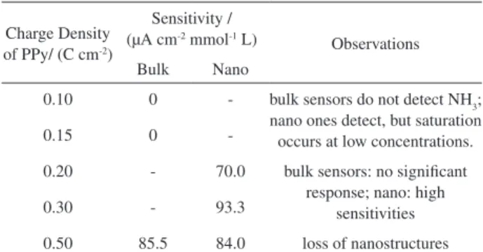
the performances of these sensors with bulk ones, synthesized in similar conditions, except for the templating with polystyrene particles. Several bulk and nanostructured ammonia sensors were prepared, changing the charge density of polypyrrole employed from 0.10 to 0.50 C cm-2. Table 2 summarizes the comparisons among these sensors in terms of sensitivities towards ammonia detection. These sensitivities were obtained from amperometric data in the same conditions employed in the experiments of Fig. 6. It was observed that bulk sensors presenting up to 0.15 C cm-2 of polypyrrole did not sense ammonia; on the other hand, the corresponding nanostructured sensors provided amperometric responses, but saturation occurs at concentrations as low as 40.0 µmol L-1. From 0.20 to 0.30 C cm-2, bulk sensors presented very poor current increases towards ammonia addition, while the sensitivities obtained with both nanostructured films were high, 70 and 93.3 µA cm-2 mmol-1 L, respectively. These results show the benefits of performing the nanostructuration of the polymeric transducer: smaller amounts of polymer are necessary to sense ammonia in a more sensitive way with a fast response. This can be attributed to the larger active area obtained, as showed before, but also to the increased and faster analyte (ammonia) diffusion inside the interconnected pore array, when compared with a compact bulk film. To corroborate this assumption, some calculations were done based on geometry and taking into account that only the outer layer of nanostructured polypyrrole. The surface area obtained with these nanostructures is only about 2 times larger than the bulk film. So, as stated before, the increase in sensitivities is a consequence not only of the larger surface area obtained with the nanostructures, but shows that greater access of the analyte to the bulk of the polymer through the pores plays a very important role in this case.
When 0.50 C cm-2 of polypyrrole was electrodeposited to form bulk or nano sensors, the sensitivities obtained in both cases were of the same order of magnitude (85.5 - bulk
Figure 5. FESEM image of nanostructured poly(pyrrole) obtained through the colloidal template method.
Figure 6. (a) Ammonia amperometric detection by nanostructured poly(pyrrole) of 0.30 C cm-2. Working potential = 0.35 V, 0.1 mol L-1
borate buffer (pH 10.0), under stirring. Periodic NH4Cl solution additions increased the total concentration in 20 µmol-1 L. (b) Analytical curve
obtained from amperometry data. Sensitivity = 93.3 µA cm-2 mmol-1 L.
Table 2. Sensitivities of nanostructured and bulk sensors towards ammonia as a function of charge density of polypyrrole
Charge Density of PPy/ (C cm-2)
Sensitivity / (µA cm-2 mmol-1 L)
Observations Bulk Nano
0.10 0 - bulk sensors do not detect NH3; nano ones detect, but saturation occurs at low concentrations.
0.15 0
-0.20 - 70.0 bulk sensors: no significant response; nano: high
sensitivities
0.30 - 93.3
and 84.0 - nano). This result is due to the fact that under these conditions, polypyrrole has grown over the template, covering it, as explained in the scheme presented in Figure 7. In this case, the nanostructured profile is lost, and the final result is a bulk film, explaining the observed sensitivities.
Nanostructured manganese dioxide films. Application in supercapacitors
As explained before, the charge applied in the electrodeposition process cannot be so high otherwise the film will grow above the nanospheres template; for MnO2 electrodeposition, different charge values were applied in order to achieve the optimized value. Films obtained by applying a cathodic current of 240 µA during different deposition times were characterized by FESEM, and a maximum time of 2 min (charge applied = 90 mC cm-2) was obtained as shown in Figure 8. From the images, it is possible to observe that a highly porous film was formed as it is possible to see that the pore distribution is tridimensional and is present over the entire electrode area. It is also possible to note that the oxide has grown on the surface of the nanospheres rather than fillings the space between them. This has happened because approximately half of obtained MnO2 was deposited chemically, which can occur both over the substrate and around the nanospheres. Film thickness was measured from cross-section FESEM images from the film and the value obtained is: (2.3 ± 0.6)µm.
Supercapacitors or electrochemical capacitors are charge storage devices that present capacitance values from 20 to 200 times higher than conventional capacitors as the charge storage mechanism in this kind of device involves both charge separation in the electrostatic double-layer and pseudocapacitance, which is related to redox reactions taking place at the electrode surface.28 As they present higher specific energy than conventional capacitors and higher specific power than batteries, supercapacitors fill the gap between conventional capacitors and batteries29 and can be applied alone as an energy-storage system for high power applications or together with a high energy device when both high power and energy are necessary. In the latter case, this combination can improve energy efficiency due to fact that supercapacitors present fast charge/discharge response; thus, they can be applied in industrial equipments, and vehicles.30
The most studied materials for supercapacitors are: carbon,31 conducting polymers32 and metal oxides.33 The last two systems involve mainly pseudo-Faradaic reactions while the first involves only double-layer capacitance. Concerning metal oxides, RuO2 presents very high capacitance values, but this material presents a high cost which makes it commercially unviable.
Other, less expensive, materials have been studied for this purpose, such as: iron,34 indium,35 tin,36 vanadium37 and manganese oxides. The last is a low cost, environmental friendly, non-toxic material that has been studied as an electrode for both batteries38 and supercapacitors.39-42
The performance of a supercapacitor is governed by the electrode material`s specific capacitance and system voltage. Specific capacitance, which is the charge storage capacity per mass of material, is strongly dependent on the electrode´s superficial area. The larger the superficial area, the more sites will be available for superficial redox reactions, improving the specific capacitance of the material. Thus, obtaining a highly porous film is of crucial importance for this kind of application. Electrochemical results obtained with nanostructured MnO2 electrodes prepared by electrodeposition over polystyrene nanospheres are discussed in the following paragraphs.
Electrodeposition of MnO2 over a polystyrene template was monitored by the EQCM technique in order to obtain
Figure 7. Scheme of polypyrrole growth over a polystyrene particle template.
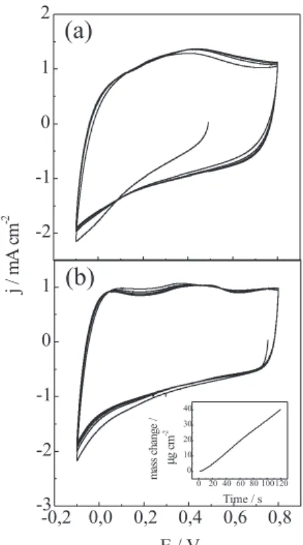
the film mass. First, the resonance frequency of the quartz electrode containing the nanospheres was measured; then the electrode was kept in permanganate solution for 45 min, the electrodeposition was carried out and the resonance frequency change was monitored during the electrochemical process. Finally, the resonance frequency of the washed and dried electrode was measured again, before removing the nanospheres. The frequency values obtained were converted into mass values by using the Sauerbrey equation.43 Mass growth is linear in the time range employed and MnO2 mass obtained after 2 min is 42 µg cm-2 (insert in Figure 9). It must be pointed out that the mass obtained by measuring the electrode´s resonance frequency before and after the electrodeposition is ca. 85 µg cm-2. This value is about twice than that obtained by monitoring the frequency change during electrodeposition because MnO2 chemical deposition also occurs while the electrode is immersed in the permanganate solution before the electrochemical process. So, the real MnO2 mass deposited over the electrode was 85 µg cm-2, corresponding to 42 µg cm-2 deposited electrochemically and 43 µg cm-2 chemically.
After removing the polystyrene with THF, the electrode containing the MnO2 film was dried in vacuum at 45 oC for 12 h and then electrochemical characterization was performed by cyclic voltammetry.
A bulk electrode with the same mass of deposited material was also characterized, in order to compare their performances. Figure 9 shows cyclic voltammograms at 50 mV s-1 recorded with both electrodes showing the rectangular shape characteristic of a capacitor behavior. For a lower scan rate (0.01 V s-1) the same behavior was observed. Performances of nanostructured and bulk electrodes were compared in terms of specific capacitance, which is the charge storage capacity per mass of material. These values were calculated as follows: first, the charge value was obtained by integrating the current vs. time curve and then this value was divided by the voltage window and the mass of material. Table 3 shows the capacitance values obtained for both electrodes at 0.01 and 0.05 V s-1.
At both scan rates, higher specific capacitance values were obtained for nanostructured electrodes. At 0.01 V s-1, an increase of 25.5% was observed while at 0.05 V s-1, the increase was of about 12%. The charge storage process occurs with faradaic reactions occurring at the surface of thematerial; so, as the nanostructured electrode presents larger superficial area than the bulk electrode, there are more sites available for charge compensation processes for the same mass of material. Nevertheless, the increase in capacitance value is not as high as expected when a nanostructured electrode is used because in a porous electrode there are problems with electrolyte permeation.
Nakayama et al.42 obtained lower capacitances values for both nanostructured and bulk MnO2 (nanostructured electrode was obtained by performing electrodeposition over 740 nm diameter polystyrene spheres from MnSO4), but, when the values of the nanostructured electrode were compared with bulk electrode, the improvement in capacitance values is much higher. The discrepancy in capacitance values of both studies can be associated with the electrodeposition method used.
On the other hand, the huge improvement in capacitance values observed in Nakayama’s contribution, when compared with the present work, can be associated with larger polystyrene spheres, diameters, which facilitates to permeation process. This aspect will be discussed in the next section.
Figure 9. j/E potentiodynamic profiles of nanostructured (a) and bulk (b) MnO2 electrodes;, v = 0.05 V s-1. Insert: Mass change vs. time for MnO
2
electrodeposition over polystyrene template.
Table 3. Specific capacitance values of nanostructured and bulk MnO2 electrodes at 0.01 and 0.05 V s-1
v/(V s-1) Nanostructured/(F g-1) Bulk/(F g-1)
0.01 357.9 266.7
Discussion
It was possible to improve porous material accessibility keeping the modified electrodes in a desiccator before electrochemical analysis. As stated before, this step was important to remove the organic solvent that could make aqueous solution penetration through the nanostructures more dificult. However, comparing the results obtained with bulk and nanostructured systems, in some cases it is possible to observe that currents achieved in the voltammograms or chronoamperograms are not so high for the macroporous materials, as might be expected because of the increase in surface area.
Contact angle experiments have shown that the interaction in the material/solution interface is not so favorable in half height macroporous systems as in bulk compounds.44 This fact can be related to the air remaining inside the pores, which creates a capillary effect that makes the accessibility to all active sites difficult.
Experiments are underway in order to make this accessibility better, but there is also another important subject to be discussed which is related with thermodynamics. The properties of surface atoms are different from those of internal atoms because there are fewer bonds linking them with qheir neighbor atoms. Consequently, the chemical potential (µ) can be described as a function of surface curvature with a radius of R. This relation is shown by Young-Laplace equation:
W Dm = 2g ––
R
which relates the chemical potential of an atom in a spherical surface with respect to a flat reference surface. In this evaluation, g is the surface energy and W is the atomic volume. The Young-Laplace equation can be generalized for any type of curved surfaces and, as a consequence, for a convex surface, the curvature is positive and the chemical potential of an atom localized in this area is higher than the one exhibited by an atom situated on a concave surface.45 Thus, thermodynamically, atoms localized on a convex surface have the highest chemical potential, whereas an atom on a concave surface exhibits a lower chemical potential and, consequently, has its stability increased.
This concept is very important to compare results presented by nanoparticles, bulk and macroporous materials. Besides, it turns more significant according to the decrease in the concave or convex surface size. Aurlier publication using spherical nanoparticles showed that the electrochemical response obtained when nanoparticles replace bulk compounds as mediator in biosensors46,47 or in
electrochemical devices48 is improved. As stated before, the improvement is related not only to the exposition of more active sites available due to the larger surface area but also to the high chemical potential presented by these atoms. As just stated, nanoparticles present high surface convex interfaces and their exposed active sites are, thermodynamically, very reactive. However, current propagation to the electrode in these cases depends on the contact between nanoparticles. Macroporous materials present high surface concave interfaces and, consequently, their stabilities are thermodynamically higher than nanoparticles. However, macroporous materials are able to propagate current through the walls of the nanostructured material, which is an important advantage over the nanoparticles.
Conclusions
Highly ordered macroporous materials were prepared by electrodeposition over colloidal polystyrene templates assembled on glassy carbon, gold or platinum substrates. The use of this method for preparation of films for different applications, like sensors and supercapacitors, shows its versatility.
In all cases, the nanostructured films obtained presented improved electrochemical performances compared with bulk materials since a higher number of active sites are exposed. However, in order to obtain a high quality film, some aspects must be considered, such as surfactant concentration, polystyrene suspension volume, charge applied in electrodeposition and surface stability.
Supplementary Information
Supplementary material is available free of charge at http://jbcs.sbq.org.br, as a PDF file, and presents experiments performed in order to optimize Triton X-100 concentration in order to stabilize the polystyrene particles over a glassy carbon electrode.
Acknowledgements
The authors are indebted to the Brazilian agencies FAPESP (proc. 03/10015-3) and CNPq. V.R.G., M.P.M. and T.M.B. thank FAPESP (Proc. 05/59560-9, 07/55299-0, 05/59135-6) for the scholarship. D.G.M. thanks The University of Florida NSF-REU Summer Undergraduate Research Program and USP for financial support.
References
2. Bardosova, M.; Tredgold, R. H.; J. Mater. Chem.2002, 12, 2835.
3. López, C.; Adv. Mater.2003, 15, 1679.
4. Braun, P. V.; Wiltziuz, P.; Nature1999, 402, 603.
5. Lee, Y. -C.; Kuo, T. -J.; Hsu, C. -J.; Su, Y. -W.; Chen, C. -C.;
Langmuir2002, 18, 9942.
6. Szamocki, R.; Velichko, A.; Holzapfel, C.; Mucklich, F.; Revaine, S.; Garrigue, P.; Sojic, N.; Hempelmann, R.; Kuhn, A.; Anal. Chem.2007, 79, 533.
7. Bartlett, P. N.; Birkin, P. R.; Ghanem, M. A.; Chem. Commun.
2000, 17, 1671.
8. Bartlett, P. N.; Ghanem, M. A.; El Hallag, I. S.; de Groot, P.; Zhukov, A.; J. Mater. Chem.2003, 13, 2596.
9. Bartlett, P. N.; Dunford, T.; Ghanem, M. A.; J. Mater. Chem.
2002, 12, 3130.
10. Luo, X.; Killard, A. J.; Morrim, A.; Smith, M. R.; Chem. Commun. (Cambridge)2007, 30, 3207.
11. Bartlett, P. N.; Birkin, P. R.; Ghanem, M. A.; Toh, C.; J. Mater. Chem.2001, 849, 11.
12. Sumida, T.; Wada, Y.; Kitamura, T.; Yanagida, S.; Chem. Comm.
2000, 1613.
13. Bartlett, P. N.; Baumberg, J. J.; Coyle, S.; Abdelsalam, M. E.;
Faraday Discuss.2004, 125, 117.
14. Bartlett, P. N.; Baumberg, J. J.; Birkin, P. R.; Ghanem, M. A.; Netti, M. C.; Chem. Mater.2002, 14, 2199.
15. Kiema, G. K.; Aktay, M.; McDermott; J. Electroanal. Chem.
2003, 540, 7.
16. Gonçales, V. R.; Salvador, R. P.; Alcântara, M. R.; Córdoba de Torresi, S. I.; J. Electrochem. Soc.2008, 155, K140.
17. Bartlett, P. N.; Electrochem. Soc. Interface2004, 13, 28. 18. Jódar-Reyes, A. B.; Ortega-Vinuesa, J. L.; Martín-Rodriguez,
A.; J. Colloid. Interface Sci.2005,282, 439.
19. Karyakin, A. A.; Gitelmacher, O. V.; Karyakina, E. E.; Anal. Lett.1994, 27, 2861.
20. Karyakin, A. A.; Puganova, E. A.; Budashov, I. A.; Kurochkin, I. N.; Karyakina, E. E.; Levchenko, V. A.; Matveyenko, V. N.; Varfolomeyev, S. D.; Anal. Chem.2004, 76, 474.
21. Ricci, F.; Palleschi, G.; Biosens. Bioelectron.2005, 21, 389. 22. Florescu, M.; Brett, C. M. A.; Anal. Lett.2005, 37, 871. 23. de Mattos, I. L.; Gorton, L.; Laurell, T.; Malinauskas, A.;
Karyakin, A. A.; Talanta2000, 52, 791.
24. Fiorito, P. A.; Brett, C. M.; Córdoba de Torresi, S. I.; Talanta
2006, 69, 403.
25. Szamocki, R.; Reculusa, S.; Ravaine, S.; Bartlett, P. N.; Kuhn, A.; Hempelmann, R.; Angew. Chem. Int. Ed.2006, 45, 1317.
26. Dall’Antonia, L. H.; Vidotti, M. E.; de Torresi, S. I. C.; Torresi, R. M.; Electroanalysis2002, 14, 1577.
27. Vidotti, M.; Dall’Antonia, L. H.; Córdoba de Torresi, S. I.; Bergamaski, K.; Nart, F. C.; Anal. Chim. Acta2003, 489, 207. 28. Sarangapani, S.; J. Electrochem. Soc.1996, 143, 3791. 29. Kotz, R.; Carlen, M.; Electrochim. Acta2000, 45, 2483. 30. Long, J. W.; Interface2008, 17, 33.
31. Taberna, P. L.; Simon, P.; Fauvarque, J. F.; J. Electrochem. Soc.
2003, 150, A292.
32. Fusalba, F.; El Mehdi, N.; Breau, L.; Bélanger, D.; Chem. Mater.
1999, 11, 2743.
33. Cottineau, T.; Toupin, M.; Delahaye, T.; Brousse, T.; Bélanger, D.; Appl. Phys. A2006, 82, 599.
34. Wang, S. Y.; Wu, N. L.; J. Appl. Electrochem. 2003, 33, 345. 35. Prasad, K. R.; Koga, K.; Miura, N.; Chem. Mater. 2004, 16,
1845.
36. Prasad, K. R.; Miura, N.; Electrochem. Comm. 2004, 6, 849. 37. Lee, H. Y.; Goodenough, J. B.; J. Solid State Chem. 1999, 148,
81.
38. Benedetti, T. M.; Bazito, F. F. C.; Ponzio, E. A.; Torresi, R. M.;
Langmuir2008, 24, 3602.
39. Shinomiya, T.; Gupta, V.; Miura, N.; Electrochim. Acta2006,
51, 4412.
40. Athouel, L.; Moser, F.; Dugas, R.; Crosnier, O.; Belanger, D.; Brousse, T.; J. Phys. Chem. C2008, 112, 7270.
41. Pang, S. C.; Anderson, M. A.; Chapman, T. W.; J. Electrochem. Soc.2000, 147, 444.
42. Nakayama, M.; Kanaya, T.; Inoue, R.; Electrochem. Commun.
2007, 9, 1154.
43. Sauerbrey, G.; Z. Phys.1959, 155, 206.
44. Abdelsalam, M. E.; Bartlett, P. N.; Kelf, T.; Baumberg, J.;
Langmuir2005, 21, 1753.
45. Cao, G.; Nanostructures & Nanomaterials. Synthesis, Properties & Applications, Imperial College Press: London, 2004. 46. Fiorito, P. A.; Gonçales, V. R.; Ponzio, E. A.; Córdoba de Torresi,
S. I.; Chem. Commun. (Cambridge)2005, 3, 366.
47. Baioni, A. P.; Vidotti, M.; Fiorito, P. A.; Córdoba de Torresi, S. I.; J. Electroanal. Chem.2008, 622, 219.
48. Baioni, A. P.; Vidotti, M.; Ponzio, E. A.; Fiorito, P. A.; Córdoba de Torresi, S. I.; Langmuir2007, 23, 6796.
Received: November 10, 2008 Web Release Date: April 9, 2009
S
u
p
p
le
m
e
nta
ry
Inf
o
rm
a
ti
o
n
0103 - 5053 $6.00+0.00
*e-mail: [email protected]
Nanostructured Thin Films Obtained by Electrodeposition over a Colloidal Crystal Template:
Applications in Electrochemical Devices
Vinicius R. Gonçales,a Mariana P. Massafera,a Tânia M. Benedetti,a David G. Moore,b
Susana I. Córdoba de Torresi*,a and Roberto M. Torresia
a Instituto de Química, Universidade de São Paulo, CP 26077, 05513-970 São Paulo-SP, Brazil
bMaterials Science and Engineering, University of Florida, P.O. Box 116400, Gainesville, Florida, USA
This supplementary material presents experiments performed in order to achieve the best Triton X-100 concentration to stabilize the polystyrene particles over a glassy carbon electrode. The same reasoning was developed to determine the best surfactant concentrations over ITO, gold and platinum substrates. Figure 1S shows the colloidal template assembled over a glassy carbon electrode using 1.0 × 10⁻⁶ mol L-1 Triton X-100 to stabilize the polystyrene
particles over the substrate, leading to a homogeneous distribution.
Figure 1S. 0.5 % monodisperse polystyrene spheres +1.0 × 10⁻⁶ mol L-1
Triton X-100 assembled over a glassy carbon electrode.
Figure 2S and Figure 3S present the polystyrene spheres deposited over the glassy carbon substrates using 1.0 × 10⁻⁵ mol L-1 Triton X-100 and 1.0 × 10⁻⁷ mol L-1 Triton
X-100, respectively. In the first case, the surfactant amount is quite high and it is possible to observe latex agglomerates distributed in different parts over the substrate. On the other hand, 0 1.0 × 10⁻⁷ mol L-1 Triton X-100 is not concentrated
enough to stabilize the polystyrene spheres, resulting in an inhomogeneous colloidal template assembly with many free glassy carbon areas.
Figure 2S. 0.5 % monodisperse polystyrene spheres + 1.0 × 10⁻⁵ mol L-1
Triton X-100 assembled over a glassy carbon electrode.
Figure 3S. 0.5 % monodisperse polystyrene spheres + 1.0 × 10⁻⁷ mol L-1