Validation of a Model for Ice Formation around Finned Tubes
Kamal A. R. Ismail*, Fatima A. M. Lino *
* State University of Campinas, Faculty of Mechanical Engineering, Department of Energy, Mendeleiev street, 200, Postal Code 13083-860, Cidade Universitária “Zeferino Vaz”, Barão Geraldo, Campinas, SP, Brazil
ABSTRACT
Phase change materials although attaractive option for thermal storage applications its main drawback is the slow thermal response during charging and discharging processes due to their low thermal conductivity. The present study validates a model developed by the authors some years ago on radial fins as a method to meliorate the thermal performance of PCM in horizontal storage system. The developed model for the radial finned tube is based on pure conduction, the enthalpy approach and was discretized by the finite difference method. Experiments were realized specifically to validate the model and its numerical predictions.
Keywords:
Finned tube, latent heat storage system, PCM, phase change, solidification, thermal conductivity enhancementI.
INTRODUCTION
Energy storage equipments are essential elements for intermittent thermal generation and/or conservation systems. Sensible and latent heat storage systems are among the well dominated thermal storage technologies. Latent heat storage is most preferred because of its high energy density and nearly isothermal behavior during the charging and discharging processes. Its major disadvantage is the low thermal conductivity which provokes slow thermal discharging and charging processes. Many techniques were tried to meliorate the effective thermal conductivity of the PCM storage system. Liu et al. [1] found that the fin effectively improved both heat conduction and natural convection. Kayansayan and Acar [2] realized a numerical and experimental investigation on a latent heat thermal energy storage system dominated by heat conduction and found good agreement between the numerical predictions and the experimental measurements. Yuksel et al. [3] proposed a theoretical approach for the prediction of time and temperature during phase change in the latent heat storage and found good agreement between the theoretical results and the experimental data was good. Jegadheeswaran and Pohekar [4], Chintakrinda et al. [5] used different approaches to meliorate the thermal conductivity of the PCM by using metallic powders dispersed in the PCM, the use of graphite foam with infiltrated PCM, aluminum foam with infiltrated PCM, and PCM with 10 wt% graphite nano-fibers. They found significant effect on the thermal response of the system.
Rahimi et al. [6] conducted experimental investigation on finned tubes submersed in PCM while Ismail et al. [7] and Ismail et al. [8] used numerical approach validated with experiments to investigate phase change processes around finned-tubes. It was shown that, using fins enhances melting and solidification processes.
The main objective of the present work is to validate the numerical model and the numerical predictions developed by the authors for the solidification around finned tubes.
II.
FORMULATION OF THE MODEL
The present problem treats the solidification of PCM inside a storage tank of the latent heat type composed of a bundle of horizontal tubes fitted with radial fins extending along the length of the storage tank. A representative section of this configuration composed of the finned tube surrounded by a symmetry circle and extending along the storage tank is shown in Fig. 1. The symmetry circle is defined as the limiting boundary beyond which there is no heat transfer or phase change. The finned tube is surrounded by the PCM while the cooling fluid flows inside the finned tube. Fig. 1 shows a general layout of the problem and the instantaneous interface between the solidified and the liquid PCM.
In order to formulate the model a two dimensional coordinate system is used, where the z direction is along the finned tube axis and the radial coordinate is along the tube radius. Some assumptions are admitted to enable formulating the model. For example, the PCM is considered as a pure substance, incompressible, has constant phase change temperature, and initially in the liquid phase. The physical properties such as density, specific heat and thermal conductivity of the solid and liquid phases are known. The mechanism of heat transfer during the phase change process is controlled by pure conduction and convection in the PCM liquid phase is neglected.
Figure 1 Sketch of the problem of phase change around a finned tube.
This problem was treated by the authors [9] and can be consulted for more details about the numerical solution and predictions. To highlight the essential points of the developed model we present the unsteady governing equations and the associated boundary conditions in cylindrical coordinates for the problem shown in Fig.1.
The energy equation of the solid PCM
1
s s s
s s s s
T T T
c r k k
t r r r z r
(1)
Where sis the density of the solid PCM,
s
c is the solid PCM specific heat,ks is the thermal
conductivity of solid PCM, Tsis the temperature of the solid phase, r is the radial coordinate, z the axial position along the tube axis and t is the time. The energy equation of the liquid PCM
1
l l l
l l l l
T T T
c r k k
t r r r z r
(2)
Where the subscript l refers to the liquid phase.
The boundary conditions at the solid / liquid interface
2
1
s l
s l s
T T s s
k k L
r r z t
(3)
s l m
T T T
r s t( ) (4) Where Lis the latent heat, s(t)is the instantaneous interface position while the subscript m refers to phase change temperature.
The boundary condition at the wall of the tube
The boundary condition at the symmetry circle
e
r r T 0
r
(6) The boundary condition at the tube entrance section
i
z z T 0
z
(7) The boundary condition at the tube exit section
t
z z T 0
z
(8) Where the subscript w refers to the tube wall, e refers to the symmetry boundary, i refers to the inlet section while t refers to the exit section. The initial and final conditions
0
( , , ) m
T r z t T T
( , , f) m
T r z t T T (9)
where t0and tf refer to initial and final
conditions respectively while is half of the phase change temperature range.
The above system of equations and boundary conditions were treated following the enthalpy method due to Bonacina et al. [10] discretized by finite difference and implemented in a computational code. Numerical tests were realized varying the grid size and the time step to ensure independent results of the choice of these values. The grid points most adequate in terms of precision and computational time are found to be 45 along the tube and 33 points along the radial fin. The time step is taken as 10-3 s. These values are used in all the numerical simulations.
III.
EXPERIMENTAL ANALYSIS
thermocouples were calibrated to within ±0.5 oC, the image conversion precision to within ±0.1mm while the mass flow rate (measured by a calibrated orifice plate) to within ±10-4 kg/s.
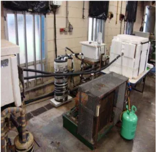
Measurements were usually taken when the desired testing conditions were achieved, that is the temperature of the working fluid in the finned tube, temperature of the ethanol tank, temperature of the PCM, and the mass flow rate of the secondary fluid. The initial conditions are recorded and the chronometer is switched on to initiate the test. During the first hour, all measurements including a photograph of the finned tube are registered every 5 minutes. During the subsequent two hours the photograph the finned tube and the other measurements are registered every 15 minutes. After the third hour, the time interval is increased to 30 minutes and measurements are realized in the same manner until the end of the test. The test is terminated when no change in temperature or interface position is registered during three successive time intervals. More details about the experimental measurements and method of treatment can be found in [11].
Figure 2 Photograph of the experimental installation.
IV.
RESULTS AND DISCUSSION
The model and the numerical predictions were validated against experiments conducted by the authors. Fig. 3 shows a comparison between the numerical predictions of the interface velocity and the experimental measurements for the case of tube with 95 mm fin diameter. As can be seen the agreement is good. Fig. 4 shows a similar comparison for the case of fin with 75 mm diameter indicating a relatively good agreement.
Figure 3 Numerical and experimental comparison of the instantaneous interface velocity for a finned tube
of 95 mm diameter.
Figure 4 Numerical and experimental comparison of the instantaneous interface velocity for a finned tube
of 70 mm diameter.
Comparative results for the solidified mass fraction are shown in Figs. 5 and 6. Fig. 5 shows a comparison of the predicted solidified mass fraction and the experimentally determined mass fraction. As can be seen the agreement is very good and hence confirming the suitability of the model and the method of solution to handle the problem of solidification around finned tubes.
Figure 5 Numerical and experimental comparison of the solidified mass fraction for a finned tube of 95
mm diameter.
Figure 6 Numerical and experimental comparison of the solidified mass fraction for a finned tube of 70
mm diameter.
Figure 7 Numerical and experimental comparison of the radial interface position for a finned tube of 40
mm diameter.
Fig. 7 shows a comparison between the numerical predictions and experiments of the
diameter. As can be seen the agreement is reasonably good. The differences can be attributed to possible heat losses not accounted for in the numerical model.
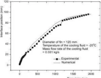
Fig. 8 shows a comparison between the numerical predictions and experiments of the position of interface for the case of 120 mm fin diameter. As can be seen the agreement is reasonably good. The numerical predictions are slightly higher than the experimental measurements due to possible thermal losses in the test section.
Figure 8 Numerical and experimental comparison of the radial interface position for a finned tube of 120
mm diameter.
V.
CONCLUSIONS
The model and numerical results were validated experimentally using different fin diameters and a wide range of operational parameters as mass flow rate and various values of wall temperature. The agreement is found to be satisfactory and hence validating the model and the numerical predictions.
ACKNOWLEDGEMENTS
The authors wish to thank the CNPq for the PQ grant to the first author and the post doctorate grant to the second author.
REFERENCES
[1]. Z. Liu, X. Sun, C. Ma, Experimental investigations on the characteristics of melting processes of stearic acid in an annulus and its thermal conductivity enhancement by fins, Energy Conversion and Management, 46, 2005, 959–969. [2]. N. Kayansayan, M. A. Acar, Ice formation
[3]. N. Yuksel, A. Avci and M. Kilicn, A model for latent heat energy storage systems, Int. J. Energy Research, 30, 2006, 1146–1157. [4]. S. Jegadheeswaran, S. D. Pohekar, Energy
and exergy analysis of particle dispersed latent heat storage system, Int. Journal of Energy and Environment, 1(3), 2010, 445-458.
[5]. K. Chintakrinda, R. D. Weinstein and A. S. Fleischer, A direct comparison of three different material enhancement methods on the transient thermal response of paraffin phase change material exposed to high heat fluxes, Int. Journal of Thermal Sciences, 50, 2011, 1639-1647.
[6]. M. Rahimi, A. A. Ranjbar, D. D. Ganji, K. Sedighi, and M. J. Hosseini, Experimental investigation of phase change inside a finned-tube heat exchanger, Hindawi Publishing Corporation Journal of Engineering, 2014, Article ID 641954, 11 pages,
http://dx.doi.org/10.1155/2014/641954. [7]. K. A. R. Ismail, M. M. Gonçalves and F. A.
M. Lino, A parametric study of solidification of PCM in an annulus with alternating fins, Int. Journal of Research in Engineering and Advanced Technology, 3(4), 2015, 188-202, August-September. [8]. K. A. R. Ismail, M. M. Gonçalves and F. A.
M. Lino, Solidification of PCM around a finned tube: modeling and experimental validation, Journal of Basic and Applied Research International, 12(2), 2016, 115-128.
[9]. K. A. R. Ismail, J. R. Henriquez L. F. M., Moura, and M. Ganzarolli, Ice formation around isothermal radial finned tubes, Energy Conversion and Management, 41, 2000, 585-605.
[10]. C. Bonacina, G. Comini, A. Fasano, M. Primiceiro, Numerical solutions of phase change problems, Int. Journal Heat and Mass Transfer, 16(15), 1973, 1825-1832. [11]. K.A.R. Ismail, P. D. Silva, and F.A.M.