978-1-5090-1393-7/16/$31.00 ©2016 IEEE
Bidirectional DC-DC Converter with High Voltage
Gain for the Charge/Discharge Control of Storage
Systems
V. Fernão Pires
ESTSetúbal / Instituto Politécnico Setúbal
INESC-ID Lisboa Setúbal, Portugal [email protected]
Daniel Foito
ESTSetúbal / Instituto Politécnico Setúbal Setúbal, Portugal [email protected]
J. F. Martins
CTS/UNINOVA FCT/UNL Caparica, Portugal [email protected]Abstract—This paper presents a study of a bidirectional dc-dc converter with high voltage gain to regulate the charge and discharge of electrochemical storage systems. The converter is characterized by quadratic voltage gain characteristics in both directions. In this context it can be used to regulate a dc interface between the storage system and a dc/ac converter connected to the electrical grid. It will be analysed the converter in ideal and non-ideal conditions. A control system to regulate the output voltages and currents are also proposed. Simulation results are presented in order to validate the control system associated to the converter for the charge/discharge of the storage system.
Keywords—bidirectional; dc-dc converter; extendend voltage gain; quadratic converter I. INTRODUCTION
The growing integration of distributed energy resources (DER) has a direct impact on the performance of the electrical networks. Thus, in order to overcome problems related to the DER such as intermittent generation or power quality storage systems associated to the renewable sources are now becoming a requirement. However, in the context of power distribution systems that integrate electrochemical storage systems such as batteries or supercapacitors, dc bus with 400 V or higher are now becoming very important [1]. These systems normally require bidirectional dc/dc converters to charge/discharge the storage systems. However, in order to avoid a high number of storage elements in serial, these converters should have a high voltage gain.
Several dc/dc power converter topologies with high voltage gain have been developed. These power converters were based in two types of categories: isolated and non-isolated [2]. Regarding the isolated topologies they are characterized by high number of switching devices [3,4]. On other hand, these topologies normally suffer from high switching losses of the power switches. Thus, topologies with soft switching were also proposed [5,6]. The drawback of this solution is the cost and complex control system. For the category of non-isolated several topologies have also been proposed. In this category one of the most used topologies is the buck-boost converter. In the classical converter the polarity of dc buses is reverse with respect to a common ground [7]. This drawback can be overcome by adding more switches to this configuration as presented in [8]. To reduce the problem of the switching losses, topologies with soft switch were also proposed [9]. However, these topologies present an important limitation when is required a high voltage ratio. In this way, other topologies that allow to extend the voltage ratio were proposed. A topology that uses a coupled-inductor bidirectional converter scheme was proposed in [10]. Other topology that does not require coupled inductors were proposed in [11]. This topology is based on the SEPIC converter. However, it allows to extend the voltage ratio. A non-isolated bidirectional DC/DC power converter with quadratic voltage gain characteristics was presented in [12]. However, in this study it is only controlled the output voltage through a simple integral regulator. Thus it only can be used in standalone application. On other hand, the way that is controlled does not ensure stability of the system [13].
In this work is proposed the study in ideal and non-ideal conditions of the bidirectional quadratic dc/dc power converter for the electrochemical storage systems. A fast and robust control system is also proposed. This controller is based on the sliding mode approach. In order to verify these characteristics several tests will be presented.
II. BIDIRECTIONAL DC-DC CONVERTER
One of the dc-dc power converters well adapted for applications where high voltage range is required is the quadratic boost converter [14]. This converter (Fig. 1) is characterized by conversion ratio that has a quadric dependence of the duty-cycle. However, this converter presents a unidirectional characteristic which can be important drawback in several applications.
Fig. 1. Quadratic boost converter
In order to provide bidirectional characteristic extra power semiconductors are required as presented in Fig. 2 is proposed. In this study the converter will be analyzed and controlled for the charge/discharge of a storage system. This converter is considered connected to a constant DC bus (for example for renewable distributed resources connected to a grid).
Fig. 2. Quadratic converter with bidirectional characteristics
The converter in discharging mode (boost mode) and in continuous conduction mode CCM) has two stage modes. In stage 1 the power switch T2 is turned-on charging the inductors. The capacitor C will discharge for the inductor L2. In the second stage power switch T2 is turned-off discharging both inductors to the capacitor C and DC bus. According to this, the voltage gain in this mode is given by (1) where is possible to verify the quadratic gain.
(
)
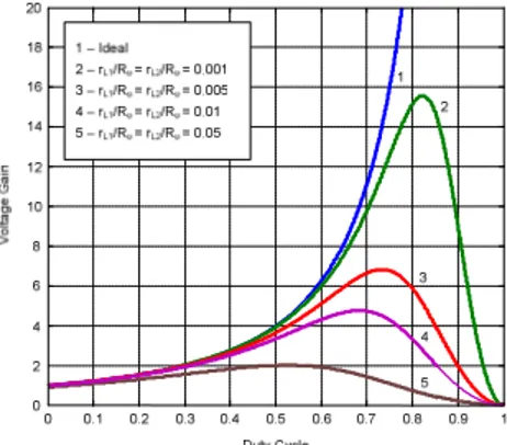
2 _ 1 1 δ − = st bus DC V V (1)For the non-ideal conditions it will be considered that the losses in the inductors will be represented by an internal resistance (a serial connection of L1 with rL1 and L2 with rL2). Thus, considering an equivalent resistor Ro as load, the following voltage gain in
non-ideal conditions can be obtained:
(
)
2 2(
)
2 1 _ 1 1 1 1 δ δ + + − − = o L o L st bus DC R r R r V V (2)Using equation (2) for different values of rL1/Ro =rL2/Ro, the converter gain faction of the duty cycle can be plotted as presented in Fig. 2. The figure shows the limitation of the gain and for example with rL1/Ro =rL2/Ro =0.001a maximum gain near 15 is obtained.
For the system in charging mode (buck mode) and considering again the converter in CCM, it may be considered four stages. In the first stag the power switches T1 and T3 are turned-on. In this condition both inductors and capacitor are in charging mode. In the
second stage switch T1 is turned-on and the other in turned-off. The inductor L1 will be in charge mode and the inductor L2 and capacitor C will be discharge mode. In the third stage only the switch T3 will be in turned-on condition. Due to this the inductor L1 is in discharge mode and inductor L2 and capacitor C will be in charge mode. Finally, the fourth stage is characterized by all controlled switches in turned-off condition. In this condition both inductors are in discharge mode and the capacitor will be in charge mode. In accordance with this, in continuous conduction mode the voltage gain is given by:
2 _ δ = bus DC st V V (3)
III. CONTROL OF THE SYSTEM
Since the bidirectional DC/DC converter will be used for the charge and discharge of storage systems, it will be adopted a current control system. Considering this situation and the inherently variable structure of the power converter will be adopted a non-linear controller (sliding mode). However, two different controllers will be used considering that the converter is in charge or discharge mode.
Considering that the system is in discharge mode it is only required to consider as reference the current of the storage system. According to this and from the analysis of the circuit is possible to verify that the state space equation related with this inductor current is (where α is a boolean variable that represents the switch on or off).
(
2)
1 _ 1 1 = − 1−α L V L V dt diL i DC bus (4)Taking into consideration the state space equation it can be concluded that the inductor current has a strong relative degree of one. Thus, the following sliding surface can be obtained:
( )
1, 1 11iL t iLref iL
S = − (5)
The convergence of the system to the reference value is ensured by the following stability condition [15]:
( ) ( )
, 1, 0 1 1 1 < dt t i dS t i S L L (6)The previous stability condition is ensured by a hysteresis comparator with a width of 2ε (instead of a simple comparator is used a hysteresis to limit the switching frequency)) according the following condition:
( )
( )
, 0 0 1 0 , 2 1 2 1 1 1 1 1 1 1 1 1 1 1 = ⇒ < ⇒ ↓ ⇒ < ⇒ − < = ⇒ > ⇒ ↑ ⇒ > ⇒ + > α ε α ε dt di i i i t i S dt di i i i t i S L L L ref L L L L L ref L L (7)When the system is in charge mode the circuit works as cascade structure. Thus, beside the control of the storage current will also be controlled the capacitor voltage. The control of the storage current is made through the sliding surface described in (5). However, regarding the voltage capacitor is possible to verify that the state space equations related with the capacitor voltage can be given by: − = − = 2 3 _ 1 2 1 2 L v C V dt di C i C i dt dv C bus DC L L L C α α (8)
Considering vC voltage as the controlled output, from the input-output linearization of the previous space model the state-space equations in the controllability canonical is:
− − = dt di C v C L C V v dt d L C bus DC C 1 1 2 3 2 _ α 1 α θ θ (9) where θ 2 1 α1 C i C iL L − =
From (9) it is possible to confirm that the capacitor voltage vC has a strong degree of two [15]. According to this and considering the feedback errors the following sliding surfaces are obtained:
2 1av L L C i i dt dv − ≈ (10)
(
)
(
)
− − + − = C i i dt dv v v t v S C, Cref C Cref L1av L2 2 β (11)Where is β a parameter related to the time constant of the desired first order response of the capacitor voltage vC (β>0)
The reaching-mode and sliding-mode stability conditions, or simple energy flow considerations (12) give the switching strategy relating with the sliding surface (11) and with the switching variable α3.
(
)
(
,)
0 1 , 3 2 2 3 2 2 = ⇒ ↓ ⇒ ↓ ⇒ < ⇒ − < = ⇒ ↑ ⇒ ↑ ⇒ > ⇒ + > α ε α ε L C C Cref C L C C Cref C i v v v t v S i v v v t v S (12)Where this is implemented through a hysteresis comparator with a width of 2ε.
IV. SIMULATION RESULTS
In order to verify the performance of the described bidirectional quadratic DC/DC converter several simulation tests were performed. In these tests, it was considered the following parameters: L1=L2=1mH and C=100µF. It was considered a storage
system with 48 V and a dc bus with 400 V. The first test was made considering the storage system in discharge mode. Fig 5 shows the current in the storage system for an initial reference of 10 A and a suddenly change for 25 A at 0.04 s. From this result is possible to verify that the current follows the reference and that the presents a fast response for the suddenly change in the current reference. The ripple in the current is fixed (0.15 A) due to the sliding mode controller. Fig. 6 shows the voltage at the terminals of the capacitor for the same test. In this mode, the capacitor voltage is not controlled. However, as can be seen by this figure this voltage is stable although with a change in their value after the change of the current reference.
Fig. 5. Voltage at the capacitor for the storage system in discharge mode
Tests with the storage system in charging mode were also performed. In Fig. 7 is presented the current in the storage system for a current reference of -15 A and a suddenly change to -20A. This result shows again that the current follows the reference and presents a fast response. In this mode the voltage at the terminals of the capacitor is also controlled. In this test was used a reference of 150 V. The time behavior of the capacitor voltage is presented in Fig. 8. From this result is possible to verify that the voltage follows the reference and presents a fast response to perturbations. On other hand, since now this voltage is controlled the perturbation when there is a change in the reference is much smaller when compared with the previous test.
Fig. 6. Current of the storage system in charge mode
Fig. 7. Voltage at the capacitor for the storage system in charge mode
A test where the storage system starts in discharge mode, change to charge mode and back to discharge mode was also performed (from 15 A to -10A and to 10A). Fig. 9 shows the obtained results for the current in the storage system. As can be seen by this figure the response of the system is accurate and fast. The obtained result for the capacitor voltage is presented in Fig. 10. In this case, in discharged mode this voltage presents variations since is not controlled. In charged mode this voltage is controlled with a slightly higher voltage.
Fig. 9. Voltage at the capacitor for the storage system in charge mode
V. CONCLUSIONS
The control of a bidirectional DC/DC converter with high voltage gain that can be used in storage systems where presented in this work. The converter presents a voltage gain with quadratic characteristics. The converter was firstly analyzed in ideal and non-ideal conditions. From this analysis it was possible to verify that the gain can be highly affected by the internal resistance of the inductors. For the control of the converter was proposed a sliding mode controller for the charge and discharge mode. In discharge mode it is only controlled the output current of the storage system. However, in charge mode besides the input current of the storage system it is also controlled the intermediate capacitor. Several simulation results were presented in order to verify the characteristics of the converter with the adopted control system for the charge/discharge of storage systems.
ACKNOWLEDGMENT
This work was supported by national funds through FCT – Fundação para a Ciência e a Tecnologia, under projects UID/CEC/50021/2013 and UID/EEA/00066/2013.
REFERENCES
[1] A. Scalfati, M. Roscia, M. Fantauzzi, D. Iannuzzi, M. Pagano, “Building DC microgrids: Planning of an experimental platform with power hardware in the loop features,” 4th International Conference on Renewable Energy Research and Applications, pp. 1507-1512, Nov. 2015.
[2] V. Fernão Pires, Enrique Romero-Cadaval, D. Vinnikov, I. Roasto, J. F. Martins, “Power converter interfaces for electrochemical energy storage systems – A review,” Energy Conversion and Management, vol. 86, pp. 453-475, Oct. 2014.
[3] B. Zhao, Q. Yu, W. Sun, “Extended-Phase-Shift Control of Isolated Bidirectional DC–DC Converter for Power Distribution in Microgrid,” IEEE Transactions on Power Electronics, vol. 27, No 11, pp. 4667-4680, Nov. 2012.
[4] M. Nowak, J. Hildebrandt, P. Luniewski, “Converters with AC transformer intermediate link suitable as interfaces for supercapacitor energy storage,” Power Electr Specialists Conf, vol. 5, pp. 4067- 4073, Jun. 2004.
[5] E. Hiraki, K. Yamamoto, T. Tanaka, T. Mishima, “An Isolated Bidirectional DC-DC Soft Switching Converter for Super Capacitor Based Energy Storage Systems,” IEEE Power Electronics Specialists Conference, pp. 390-395, Jun. 2007.
[6] Y. Miura, M. Kaga, Y. Horita and T. Ise, "Bidirectional Isolated Dual Full-bridge dc-dc Converter with Active Clamp for EDLC" The IEEE Energy Conversion Congress and Exposition, pp. 1136-1143, Sep. 2010.
[7] K. Zhiguo, Z. Chunbo, Y. Shiyan, C. Shukang, “Study of Bidirectional DC-DC Converter for Power Management in Electric Bus with Supercapacitors,” Vehicle Power and Propulsion Conf, pp. 1-5, 2006.
[8] F. Caricchi, F. Crescimbini, F.G. Capponi, L. Solero, “Study of bi-directional buck-boost converter topologies for application in electrical vehicle motor drives,” Applied Power Electronics Conference and Exposition, pp. 287-293, Feb. 1998.
[9] E. Hiraki, K. Yamamoto, T. Tanaka, T. Mishima, “An Isolated Bidirectional DC-DC Soft Switching Converter for Super Capacitor Based Energy Storage Systems,” Power Electr Specialists Conf, pp. 390-395, Jun. 2007.
[10] R.-J. Wai, R.-Y. Duan, “High-Efficiency Bidirectional Converter for Power Sources With Great Voltage Diversity,” IEEE Transactions on Power Electronics, vol. 22, No 5, pp. 1986-1996, Sep. 2007.
[11] A. A. Fardoun, E. H. Ismail, A. J. Sabzali, M. A. Al-Saffar, “Bidirectional converter for high-efficiency fuel cell powertrain,” Journal of Power Sources, vol. 249, pp. 470–482, March 2014.
[12] O. Ray, S. Mishra, A. Joshi, V. Pradeep and A. Tiwari, “Implementation and control of a bidirectional high-gain transformer-less standalone inverter,” IEEE Energy Conversion Congress and Exposition (ECCE), pp. 3233-3240, 2012.
[13] J. Levya-Ramos, M.G. Ortiz-Lopez, L.H. Diaz-Saldierna, J.A. Morales-Saldana, "Switching Regulator using a Quadratic Boost Converter for Wide DC Conversion ratios," in IET Power Electronics, vol. 2, pp. 605-613, October 2009.
[14] D. Maksimovic, S. Cuk, “Switching converters with wide dc conversion range,” IEEE Transaction on Power Electrononics, vol. 6, No 1, pp. 151-157, Aug. 2002.
[15] W. Gao, J. Hung, “Variable structure control of nonlinear systems: a new approach”, IEEE Transactions on Industrial Electronics, vol. 40, no. 1, pp.45-55, 1993.