Experimental and numerical investigation on the shock characteristics of
U-notched ZL205A specimens under dynamic mixed-mode loading
Abstract
Shock environment assessment and improvement during stage separation is an important issue of concern in aerospace engineering. This paper focuses on shock response caused by dynamic fracture of aluminum alloy separation plate, which usually undergoes mixed mode loading during separation. Based on Split Hopkinson Tensile Bar (SHTB) apparatus, five groups of U-notched ZL205A specimens with different loading angles (0°, 30°, 45°, 60°, and 90°) are de-signed to simulate mixed mode loading for shock characteristics testing. There piezoelectric accelerometers are used to measure the acceleration time histories, and the maximum shock response spectrum (SRS) are applied for shock data analysis. Meanwhile, the ANSYS/LS-DYNA finite element software is imple-mented for numerical analysis. The actual fracture angles measured from the recovered specimens are used to describe the actual fracture modes. The numer-ical and experimental results are in good agreement, showing that the shock re-sponse along the specimen’s length and thickness directions increases with the fracture angle, while there is a slight distinction in the specimen’s width direc-tion with different fracture angles. On average, the shock response is more re-markable in pure tensile fracture mode, which is 2.6 times the pure shear frac-ture mode. As a result, increasing the study of shear fracfrac-ture component is meaningful for the shock reduction through the structural design of separation plate.
Keywords
Separation plate, mixed-mode loading, U-notched, shock characteristics, shock response spectrum
1 INTRODUCTION
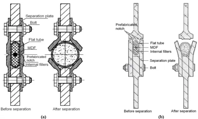
ZL205A is a series of Al-Cu-Mn cast aluminum material, which is intensively used in aerospace industry due to its high strength, low density, corrosion resistance, and high production efficiency (Li et al. 2011). An important application of ZL205A is used as separation plate material in expansion tube separation device. As a typical linear separation device, it mainly consists of a separation plate with a prefabricated notch, a flat tube, a mild detonating fuse (MDF), and some internal fillers of flat tube (Song et al. 2015; Fritz 2003), as shown in Figure 1. Upon detonating, the energy of the MDF will drive the flat tube expand rapidly which further fracture the surrounding separation plate from the prefabricated notch to achieve stage separation. Two representative separation structures of the separation device are shown in Figure 1(a) and (b). In the two structures, fracture mode of the separation plate is different since the position of the notch is different. Tensile fracture is prominent when the notch located on the center (Figure 1(a)), while mixed fracture pattern is obtained when the notch located on the upper or the lower part (Shown in Figure 1(b) is shear fracture mode). However, the fracture will produce significant shock to the separation structure owing to the sudden release of strain energy when the separation plate cracks no matter what fracture patterns (Chang and Kern 1986; Evans et al. 1987; Bement 1988). In this study, the influence to shock response of different fracture patterns is focused, which is of great significance to re-search on reducing the shock applied to equipment and astronauts in space rocket area.
Kerong Rena
Kang Lia
Yuliang Lina*
Rong Chena
Zhifeng Zhangb
Jing Sunb
a
College of Science, National University of Defen-se Technology, Changsha, Hunan, China. E-mail: [email protected], [email protected],
b Beijing Institute of Astronautical Systems
Engine-ering, Beijing, China. E-mail: [email protected], [email protected]
*Corresponding author
http://dx.doi.org/10.1590/1679-78254862
Figure 1: The expansion tube separation device. (a) Tensile fracture mode (Song et al., 2015). (b) Shear fracture mode (Fritz 2003).
From the researched literatures, there are extensive studies focus on crack mechanism and fracture properties under different loading mode, theoretically and experimentally. On theoretical aspects, there are a variety of fracture criteria proposed to describe the fracture properties of materials including crack initiation and propagation, such as the maximum tangential stress (MTS) criterion (Erdogan and Sih 1963; Li et al. 2013; Torabi and Keshavarzian 2016; Ma and Xie 2017), the mean stress (MS) criterion (Ayatollahi and Torabi 2010; Ayatollahi and Saboori 2015; Lazzarin et al. 2014), the strain energy density (SED) criterion (Torabi et al. 2015; Berto et al. 2016; Berto et al. 2015; Meneghetti et al. 2016; Berto 2016), the maximum effective stress (MES) criterion (Sajjadi et al. 2016), etc. As in experimental aspects, static or quasi-static experiments mainly have been carried out, in which the Arcan specimen and its modified configurations are extensively used (Arcan et al. 1978; Fagerholt et al. 2010; Zhang et al. 2011). As presented in Figure 2, different loading patterns of modified Arcan specimen are achieved with different loading angles. The recent experiments done by Wen et al. (2016) provide a novel method for dynamic mixed-mode fracture loading. In Wen’s study, a series of specimens with different loading angles in conjunction with the Arcan specimen (Fagerholt et al. 2010) and the widely used dumbbell-shape tensile specimen in SHTB tests are shown in Figure 3. Based on the SHTB test platform and these new-style spec-imens, the strength criterion and dynamic fracture properties of ZL205A material have been studied by Wen et al. (2016).
Figure 3: The novel specimens applied for the dynamic mixed-mode loading (Wen et al. 2016).
However, there is little research considering the shock characteristics of material under dynamic mixed-mode load-ing. Generally, shock event is a stress wave with high amplitude and high frequency, which will induce large loads on components in its path where crack initiation and fractures development can occur in brittle materials, local plastic de-formation, and accelerated fatigue life of avionics components (Piersol et al. 2010; Morais and Vasques 2017). Accord-ing to the previous reports from National Aeronautics and Space Administration (NASA) (Chang and Kern 1986; Evans et al. 1987; Bement 1988), usually, a large number of impact experiments based on the actual separation structures are conducted to determine a relatively friendly shock environment in aerospace engineering in order to ensure successful implementation of a space mission. Recently, some experimental and numerical studies on the pyroshock prediction of the separation process have been performed. Juho Lee et al. (2014; 2015a; 2015b; 2016) studied the shock propagation characteristics and the separation mechanical properties of a ridge-cut explosive bolt separation device mainly based on the Hydrocodes simulation. Their results provide a relatively comprehensive description about the separation mechanism and the shock environment characteristics of this separation device. Mijin Choi et al. (2014) preliminarily stimulated the separation process and computed the proper core loading of the expansion tube based on the AUTODYNA dynamic analysis code in combination with some separation tests. Nevertheless, their experimental and numerical procedures are only based on a specific separation device, which is inefficient and non-universal. The fracture pattern of the separation plate in linear separation device is of vital importance for the shock environment during stage separation. Consequently, it is necessary to investigate the shock characteristics of the separation plate material under dynamic mixed-mode load-ing, aiming at the structural design of the separation plate and the shock reduction design of the separation device.
In the present study, the shock characteristics of ZL205A under mixed-mode loading are researched by means of the SHTB apparatus and the finite element method. A new specimen configuration, SHTB test apparatus and piezoelec-tric accelerometers are used to characterize shock response properties. Numerical modeling based on the ANSYS/LS-DYNA finite element software is detailed for the assistant analysis in order to verify experiment results. The results in-cluding force-elongation relations, fracture angles and crack paths, shock environment characterizations are presented. The shock response under different loading angles has also been discussed based on the peak accelerations in time do-main and spectrum dodo-main.
2 EXPERIMENTAL SETUP
2.1 Specimen configuration
The chemical composition of ZL205A is presented in Table 1. Through a series of traditional SHTB tests, the basic mechanical properties of ZL205A were obtained by Wen et al, listed as Table 2.
Table 1: The chemical compositions of ZL205A (Wen et al. 2016).
Element Cu Mn Cd V Zr Re Al
Table 2: The basic mechanical properties of ZL205A (Wen et al. 2016).
Dynamic mechanical properties Value
Yield stress σy/MPa 323.2
Tensile strength σb/MPa 430.0
Fracture strain εf 0.125
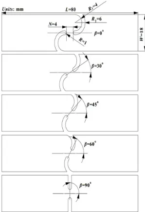
Similar with the U-notched mixed-mode tensile specimens proposed by Wen et al. (2016), the test specimen in this study is also a combination of the Arcan specimen and the SHTB tensile specimen. Differently, considering that the strength properties and the shock characteristics under mixed-mode will be studied rather than the crack initiation nor the fracture behavior, there is no prefabricated fatigue crack in the specimens and two symmetrical U-notches are manufac-tured. As shown in Figure 4, the mixed-mode load is applied to the specimens by different inclination angles (β, which is the angle between the U-notches’ midline and the bar’s axes). In particular, when β=0°, pure mode II loading (shear loading mode) is obtained; when β=90°, pure mode I loading (tensile loading mode) is obtained. The parameters R, R1, R2, β, L, W, and N in Figure 4 represent the notch radius, the inner radius, the outer radius, the inclination angle, the specimen length, the specimen width, and the length of reserved part between the two symmetrical U-notches, respec-tively. Thickness of all the specimens is 2 mm. The certain values of the parameters are shown in Figure 4. In order to verify repeatability of the experiments, three tests are performed for each inclination angle and 15 tests are carried out in the investigation totally.
Figure 4: Geometry of the specimens.
2.2 Test apparatus
Figure 5: The sketch of the SHTB test platform.
Table 3: Summary of the SHTB parameters.
Parameters Value
Diameter /mm 20
Striker bar /mm 1100
Incident bar /mm 4000
Transmitted bar /mm 2000
Young’s modulus /GPa 71
Density /(kg/m3) 2700
3 FINITE ELEMENT MODELING
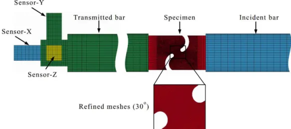
In order to get more detailed information, the corresponding numerical analysis was carried out with the AN-SYS/LS-DYNA finite element software (Version 971 smp d R7.0.0). The finite element model is shown in Figure 6. The incident bar and the transmitted bar are set as Mat Elastic model (LS-DYNA® 2007a, Keyword user’s manual Vol.II). For simplification, the stress pulse is directly applied on the striking end of the incident bar. The specimen is set as Mat Elastic Plastic Hydro Spall model (LS-DYNA® 2007b, Keyword user’s manual Vol.II) and shares common nodes with the incident bar and the transmitted bar in the glued area. The material parameters and models are summarized in Table 4. Moreover, the strain failure criterion is implemented for the specimen in the simulations that elements failure when ef-fective strain of elements exceeds the failure strain for erosion. All mesh grids of the model are hexahedral and the re-fined meshes are set up in the potential fracture area of the specimen. There are 448 elements for one sensor block and 28872~68208 elements for specimens with different loading angles. Totally, there are 208148-247484 elements for the whole model.
Table 4: The material parameters and models.
Parameters of the model Specimen Bar Sensor block
Model Elastic_Plastic_Hypro_Spall Elastic Elastic
Mass density ρ /(g/cm3
) 2.82 2.70 7.80
Shear modulus G /GPa 27.7 (none) (none)
Young’s modulus E /GPa (none) 71 210
Plastic hardening modulus Eh /MPa 910 (none) (none)
Poisson’s ratio ν 0.32 0.33 0.28
Yield stress σy /MPa 323 (none) (none)
Failure strain εf 0.125 (none) (none)
4 RESULTS AND DISCUSSION
4.1 Force elongation relations
In this part, the force-elongation relations are extracted to investigate the strength and ductility properties of speci-mens. According to the one-dimensional stress wave theory in SHTB tests, the force and elongation of the specimen can be expressed as:
b b t
f
E A
t
(1)
0
t
b i r t
e
C
d
(2)where Ab is the cross-sectional area of the output bar; Eb and Cb are Young’s modulus and one-dimensional elastic stress wave velocity of the incident/transmitted bar; εi(t) and εr(t) are strain histories of the incident and reflected waves recorded by strain gauges on incident bar; and εt(t) is strain history of the transmitted wave recorded by strain gauges on transmitted bar.
The curves in Figure 7 are all of the force-elongation testing results and numerical simulation results. And the quan-titative data of maximum force f0 and final elongation e0 are listed in Table 5. From Figure 7 and Table 5, it can be drawn a conclusion that the force increases with the loading angle when the elongation decreases as the loading angle increases, which is in good agreement with Wen’s study (Wen et al. 2016), demonstrating that the mixed loading patterns have a prominent influence on the strength and ductility properties of materials.
In addition, there are some differences between numerical simulation and experiments, that maximum force values are basically consistent but the relative error of final elongation e0 between numerical simulation and experiments in-creases with the increase of loading angle β. The possible reason maybe is that the failure strain εf, a material parameter, measured in the experiment (Wen et al. 2016) is the average strain at failure of the effective part of specimen, which is usually smaller than the true value. Therefore, when the mesh of the effective part of specimen is small enough, the final elongation of the numerical simulation will be smaller than the experimental result because the failure strain εf of the elements is assigned to the value measured in the experiment. Especially, when the effective part is under shear loading or tension-shear complex loading, this phenomenon is more obvious.
0.0 0.2 0.4 0.6 0.8 1.0 1.2
0 1 2 3 f (k N ) e(mm) Exp.-0° Exp.-30° Exp.-45° Exp.-60° Exp.-90° Simu.-0° Simu.-30° Simu.-45° Simu.-60° Simu.-90°
Table 5: Comparisons of maximum force f0 and final elongation e0 between experiments’ values and Wen's results.
Loading
angle β 0° 30° 45° 60° 90°
Maximum force
f0 /kN
Average of experiments 1.87 2.03 2.25 2.66 3.35
Wen et al. (2016) 1.73 1.97 2.23 2.56 3.17
Simulation 1.99 2.01 2.19 2.71 3.38
Relative error between exp. and Wen 8.10% 3.00% 0.90% 3.90% 5.70%
Relative error between exp. and simu. 6.03% 1.00% 2.74% 1.85% 0.89%
Final elonga-tion
e0 /mm
Average of experiments 1.16 0.58 0.44 0.37 0.31
Wen et al. (2016) 1.14 0.63 0.5 0.38 0.34
Simulation 0.77 0.37 0.31 0.27 0.27
Relative error between exp. and Wen 1.80% 7.90% 12% 2.60% 8.80%
Relative error between exp. and simu. 33.62% 36.21% 29.55% 27.03% 12.90%
4.2 Fracture angle and crack path
Figure 8 shows the recovered specimens in experiments and the Von-Misses stress distribution after fracturing in simulations. It can be seen that all the specimens were primarily fractured along a straight line. Thus, an image pro-cessing tool Drawing Board was utilized to measure the actual fracture directions (fracture angle α) of each specimen. The measured results are listed in Table 6. Two conclusions can be drawn from the recovered specimens in Figure 8 and the measured data in Table 6: the experimental results have good repeatability; the numerical results are in good coinci-dence with the experimental results. Quantitatively, the relative error of the actual fracture angle in experiments and simulations is within 10%. However, due to the complicated stress state at the notch tip, the specimens fractured not exactly along the loading angle except for the 0° and 90° specimens, which were under pure shear and pure tensile load-ing, respectively.
Table 6: Comparisons of actual fracture angle α between experiments’ values and simulations’ values.
Loading angle β
0° 30° 45° 60° 90°
Fracture angle α
Average of experiments 0° 18.3° 30.8° 44.9° 90°
Simulation 0° 19.5° 33.3° 46.3° 90°
Relative error 0 6.6% 8.1% 3.1% 0
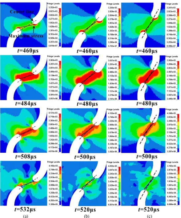
Figure 9 shows the fracture process of 30°, 45°, and 60° specimens in simulations. From the Von-Misses stress dis-tribution in Figure 9, it is obvious that the stress concentration effect in the reserved part between the two symmetrical U-notches is significant. Taking 30° specimen as a typical example, as shown in Figure 9(a), the dashed line is the center line of the notches and the continuous line reveals the maximum stress area. It’s obvious that the maximum stress which leads to the crack initiation appears at the area nearby the center line. Therefore, the actual fracture angle is smaller than the loading angle. As a result, the actual fracture angle is proposed to analyze the influence of different fracture modes in the following study.
4.3 Shock environment characterizations
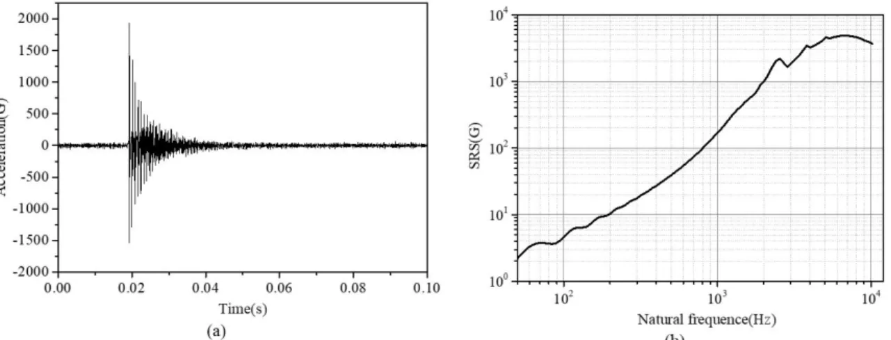
In most cases, the acceleration time history and its spectra are implemented to describe the shock environment, among which SRS is most widely used (Lee et al. 2016; Lee et al. 2012). SRS is an effective tool in vibration engineer-ing for characterizengineer-ing the transient response of the system undergoengineer-ing a shock excitation. SRS is defined as the data points of the peak acceleration response of a series of a single-degree-of-freedom (SDOF) system that possesses different natural frequencies (Irvine 2012). Since the peak acceleration is selected in different ways, SRS is classified as the posi-tive, negaposi-tive, primary, residual, and maximum SRS. In this paper, the most representative maximum SRS is employed, each SDOF system damping ratio is set as a common value of 0.05, and the natural frequency ranges from 50 Hz to 10 kHz is concerned. Figure 10 presents a typical shock pulse and the corresponding maximum SRS, where G is the local acceleration of gravity (10m/s2). The shock pulse in Figure 10(a) tends to be a complex waveform and oscillate in a symmetric manner about the zero baseline to some degree. The overall envelope of the curve shows an exponential de-cay tendency. The corresponding maximum SRS in Figure 10(b) is much more concise and its magnitude reflects the system response to the shock excitation.
Figure 10: Typical shock pulse and the corresponding maximum SRS (30°-1#). (a) Acceleration data in time domain. (b) The corresponding maximum SRS.
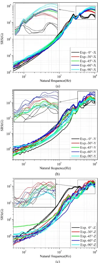
Figure 11 and Figure 12 present the maximum SRS of specimens under different loading angles in experiments and simulations, respectively. From Figure 11(a) and Figure 12(a), it can be seen that the experimental results in X-direction present a good consistency, and the trend of the experimental curves with different loading angles is consistent with the simulation results. However, since the propagation process of stress waves in Y-direction and Z-direction is more com-plicated than the wave propagation in X-direction, a small deviation of the actually fracture direction and the stress wave multiple reflections in the radial direction both may lead to deviation amplification. So the shock measurement curves of repetitive experiments in Y-direction and the Z-direction are not with good consistency. As a result, the shock character-istics in Y-direction and Z-direction only are analyzed by numerical simulation with no choice.
Figure 12: Maximum SRS in simulations. (a) X-direction. (b) Y-direction. (c) Z-direction.
4.4 Further discussion
Since the peak value is generally the most important and representative value for the shock response evaluation, the peak values in time domain and SRS are extracted to quantitatively analyze the shock characteristics under dynamic mixed loading. Meanwhile, it should be point out that only the shock peak values in X-direction are investigated because the experimental results in Y-direction and Z-direction are lack of good consistence and only the axial stress along the bar direction (X-direction) can be measured in the SHTB experiments.
Table 7: Comparisons of peak values in X-direction between experiments’ values and simulations’ values.
Loading angle β 0° 30° 45° 60° 90° I/II
Peak value in time domain /G
Average of experiments 1202 1951 2530 2617 3366 2.8
Simulation 1590 2246 2558 2939 3820 2.4
Relative error 32% 15% 1% 12% 14%
Peak value in SRS /G
Average of experiments 3166 5158 6186 6556 8244 2.6
Simulation 4918 6914 7859 9048 11419 2.3
Relative error 55% 34% 27% 38% 39%
The average value of I/II (pure mode I/pure mode II) is 2.6, with standard deviation 0.28.
Figure 13 (a) and (b) show the scatter plots of the peak value versus the fracture angle α in experiments, which show a parabola trend. The normalized fitting equation can be expressed as:
2max 0
A
A
B
(3)where Amax and α are the peak acceleration and the corresponding fracture angle, respectively. A and B are two parameters in parabola equation. α0 is the critical angle corresponding to the peak of Amax.
The fitting equations and the squared correlation coefficients are shown in Figure 13(a) and (b). Among them the squared correlation coefficient R2
(0.9633 and 0.9681) is very close to 1, which means that the fitting curves are suitable to describe trend of the scatter plots. According to the fitting equations, the peaks of Amax are obtained under the critical angle 97.04° in time domain and 95.05° in SRS, which are both closer to 90°. This indicates that pure tensile fracture contributes to the main part of the shock response in X-direction. Meanwhile, the trend of the curves illustrates that the shock response increases with the fracture angle. As a result, brief conclusions that the fracture mode of specimen is closer to shear fracture and the corresponding shock response is weaker in X-direction can be drawn preliminarily.
Table 8: Peak values of simulation results in three directions.
Loading angle β 0° 30° 45° 60° 90°
Peak value in time domain /G
X-direction 1590 2246 2558 2939 3820
Y-direction 586 448 511 508 420
Z-direction 251 388 443 511 650
Peak value in SRS /G
X-direction 4918 6914 7859 9048 11419
Y-direction 2033 1691 1825 1725 1172
Z-direction 970 1552 1860 2189 2652
5 CONCLUSIONS
In the present study, the shock characteristics of ZL205A under mixed-mode loading are preliminarily investigated by means of the SHTB apparatus. Five groups of U-notched ZL205A specimens with loading angle 0°, 30°, 45°, 60°, and 90° were designed for the mixed-mode loading and tested under the same condition. Furthermore, considering the deviation in experiments, numerical modeling based on the ANSYS/LS-DYNA finite element software is utilized for the assistant analysis along the specimen’s width and thickness directions.
The fractured specimens from experiments and simulations show that the actual fracture angles are smaller than the designed loading angle because of the complicated stress state at the notch tips except for 0° and 90° specimens. Hence, the actual fracture angles are measured to describe the fracture modes and investigate the corresponding shock response.
The maximum SRS is proposed for the shock data analysis. The experimental and numerical results show that the shock response along the specimen’s length direction increases with fracture angle. The numerical results show that there is little distinction between 0°, 30°, 45°, and 60° specimens along the specimen’s width direction, while the shock re-sponse is lower for the 90° specimens. Meanwhile, numerical results in the specimen’s thickness direction show that shock response increases with fracture angle. However, the shock response in width direction and thickness direction is observably lower than the data of length direction. Moreover, concerning the poor consistency of experimental results in the Y-direction and Z-direction in present study, further experiments and numerical simulations for separating and en-hancing the shock waves in Y-direction and Z-direction can conducted to carry on more in-depth researches in the future.
Relations between fracture angles and acceleration peaks in length direction are discussed. A parabola equation is employed to fit the peak values versus fracture angles. Results show that the acceleration peaks both in time domain and SRS fits well with the parabola curve and all the data points show an increasing trend with the fracture angle, which is of guiding significance for the structure design of separation plate. Specifically, the separation plate can be designed as shear fracture mode to attenuate shock response, which will be carried out in our following studies.
Acknowledgements
The financial support by the Natural Science Foundation of China (NSFC) [Grant no. 11672329] for this study is gratefully acknowledged.
References
Arcan, M., Hashin, Z. A., and Voloshin, A. (1978). A method to produce uniform plane-stress states with applications to fiber-reinforced materials. Experimental mechanics, 18(4), 141-146.
Ayatollahi, M. R., and Saboori, B. (2015). A new fixture for fracture tests under mixed mode I/III loading. European Journal of Mechanics-A/Solids, 51, 67-76.
Ayatollahi, M. R., and Torabi, A. R. (2010). Brittle fracture in rounded-tip V-shaped notches. Materials & Design, 31(1), 60-67.
Bement, L. J. (1988). Pyrotechnic system failures: causes and prevention. NASA.
Berto, F. (2016). Fatigue and fracture assessment of notched components by means of the Strain Energy Density. Engi-neering Fracture Mechanics, 167, 176-187.
Berto, F., Campagnolo, A., and Gallo, P. (2015). Brittle failure of graphite weakened by V-notches: a review of some recent results under different loading modes. Strength of Materials, 47(3), 488-506.
Chang, K., and Kern, D. (1986). Super zip (linear separation) shock characteristics. NASA.
Choi, M., Lee, J. R., and Kong, C. W. (2014). Development of a numerical model for an expanding tube with linear ex-plosive using autodyn. Shock and Vibration,2014,(2014-3-24), 2014(1), 1-10.
Erdogan, F., and Sih, G. C. (1963). On the crack extension in plates under plane loading and transverse shear. Journal of basic engineering, 85(4), 519-525.
Evans, M. J., Neubert, V. H., and Bement, L. J. (1987). Measurement, data analysis and prediction of pyrotechnic shock from pin-pullers and separation joints. NASA.
Fagerholt, E., Dørum, C., Børvik, T., Laukli, H. I., and Hopperstad, O. S. (2010). Experimental and numerical investiga-tion of fracture in a cast aluminium alloy. Internainvestiga-tional Journal of Solids and Structures, 47(24), 3352-3365.
Fritz, J. E. (2003). Separation Joint Technology. In 39th AIAA/ASME/SAE/ASEE Joint Propulsion Conference and Exhibit.
Irvine, T. (2012). An Introduction to the Shock Response Spectrum. Rev P, Vibration data.
Lazzarin, P., Campagnolo, A., and Berto, F. (2014). A comparison among some recent energy-and stress-based criteria for the fracture assessment of sharp V-notched components under Mode I loading. Theoretical and Applied Fracture Mechanics, 71, 21-30.
Lee, J. R., Chia, C. C., and Kong, C. W. (2012). Review of pyroshock wave measurement and simulation for space sys-tems. Measurement, 45(4), 631-642.
Lee, J., Han, J. H., Lee, Y., and Lee, H. (2014). Separation characteristics study of ridge-cut explosive bolts. Aerospace Science and Technology, 39, 153-168.
Lee, J., Han, J. H., Lee, Y., and Lee, H. (2015a). A parametric study of ridge-cut explosive bolts using hydrocodes. In-ternational Journal of Aeronautical and Space Sciences, 16(1), 50-63.
Lee, J., Hwang, D. H., Han, J. H., and Lee, Y. (2015b). Numerical study on pyroshock generation and propagation from pyrotechnic release devices using hydrocodes. In Proceedings of the 22nd International Congress on Sound and Vibra-tion.
Lee, J., Hwang, D. H., Jang, J. K., Kim, D. J., Lee, Y. J., and Lee, J. R., et al. (2016). Pyroshock prediction of ridge-cut explosive bolts using hydrocodes. Shock and Vibration,2016,(2016-9-20), 2016, 1-14.
Li, B., Shen, Y., and Hu, W. (2011). Casting defects induced fatigue damage in aircraft frames of zl205a aluminum alloy – a failure analysis. Materials & Design, 32(5), 2570-2582.
Li, Y., Fantuzzi, N., and Tornabene, F. (2013). On mixed mode crack initiation and direction in shafts: strain energy density factor and maximum tangential stress criteria. Engineering Fracture Mechanics, 109, 273-289.
LS-DYNA® Keyword user’s manual Volume II (Version 971) (2007a). Livermore Software Technology Corporation (LSTC), 26.
Ma, K., and Xie, H. (2017). Mixed-mode fracture investigation of PMMA with initial single/double crack (s) interfer-ence using phase-shifted coherent gradient sensing method. Polymer Testing, 59, 296-307.
Meneghetti, G., Campagnolo, A., and Berto, F. (2016). Averaged strain energy density estimated rapidly from the singu-lar peak stresses by FEM: cracked bars under mixed-mode (I+ III) loading. Engineering Fracture Mechanics, 167, 20-33. Morais, O. M. F., and Vasques, C. M. A. (2017). Shock environment design for space equipment testing. Proceedings of the Institution of Mechanical Engineers, Part G: Journal of Aerospace Engineering, 231(6), 1154-1167.
Piersol, A. G., Paez, T. L., and Harris, C. M. (2010). Harris' Shock and Vibration Handbook. Harris' shock and vibration handbook. McGraw-Hill.
Sajjadi, S. H., Salimi-Majd, D., and Ghorabi, M. O. A. (2016). Development of a brittle fracture criterion for prediction of crack propagation path under general mixed mode loading. Engineering Fracture Mechanics, 155, 36-48.
Song, B., Hu, Z., Sun, J., Liu, P., Tang, Z., and Suo, T.(2015). On the measurement of the separation time of expanding tube separation device. Journal of Experiment Mechanics, 30, 151-6.
Torabi, A. R., and Keshavarzian, M. (2016). Evaluation of the load-carrying capacity of notched ductile plates under mixed mode loading. Theoretical and Applied Fracture Mechanics, 85, 375-386.
Torabi, A. R., Campagnolo, A., and Berto, F. (2015). Local strain energy density to predict mode II brittle fracture in Brazilian disk specimens weakened by V-notches with end holes. Materials & Design, 69, 22-29.
Wen, X., Lu, F., Chen, R., Cao, L., and Lin, Y. (2016). Experimental studies on mixed‐mode dynamic fracture behaviour of aluminium alloy plates with narrow U‐notch. Fatigue & Fracture of Engineering Materials & Structures, 39(11), 1379-1390.