The Analysis of Alfv´en Wave Antenna Implementation
in the ETE Spherical Tokamak
L. F. Ruchko and R. M. O. Galv˜ao
Institute of Physics, University of S˜ao Paulo,CEP 05315-970, S˜ao Paulo, SP, Brazil
Received on 2 February, 2004; revised version received on 29 April, 2004
The preliminary design study of the Alfv´en wave system for the ETE spherical tokamak is presented. The main objective of the proposedRF system is generation of travelling Alfv´en waves, which can be used for the study of the non-inductive current drive and the plasma heating in a wide range of operational regimes, which are specific for tokamaks with small aspect ratioR/a≃1.2−1.5. The antenna system consists of four modules, which are separated by 90◦in toroidal direction. Each module has two sets ofRF current carrying
poloidal straps that are positioned symmetrically in relation to the equatorial plane of the vacuum chamber at the poloidal coordinates±45◦. The poloidal extension of each strap is approximately 90◦. The excited mode
numbers can be controlled by the phasing of the feedingRFcurrent. In the basic regime of operation, the straps in the same toroidal cross-sections are fed by the RF currents with(0,±π/2)phasing so that they can excite travelling modesM=±1,N =±1. In order to decrease the peripheryRFpower deposition and to improve the selectivity of the Alfv´en mode excitation, the inclination of the antenna straps in toroidal direction can be adjusted in the range of angles±30◦. The dependence of the antenna efficiency on the antenna orientation is
studied numerically in the frame of 1-D MHD model.
1
Introduction
The non-inductive current drive is of crucial importance to spherical tokamaks (ST). A reliable, totally non-inductive plasma current initiation and ramp-up would enable the ST option devoid of inductive transformer coils. Besides, even in present-generation machines the inductive transformer imposes a constraint on the discharge duration and current amplitude. The development of an efficient current drive method for ST is therefore very important.
The ST plasmas generally have very high dielectric constants. These features manifest themselves in the plasma resonance regions becoming almost or completely inacces-sible for the electron cyclotron resonance (ECR) and lower hybrid (LH) frequency range waves launched from the out-board plasma periphery. In the low-frequency ion cyclotron resonance (ICR) range high harmonic fast wave (HHFW) can propagate to the core of high temperature, high den-sity plasmas, and damp on electrons, and is therefore can be used for current drive in the ST plasmas. In the initial ex-periments, which have been carried out on the NSTX device [1] with the antenna phases to launch a toroidally directed spectrum, differences in loop voltage have been observed consistent with plasma current being driven by the wave. The value of the current driven, inferred from the magnetic measurements, is∼100 kA and is roughly consistent with theoretical estimates.
Yet another method of the plasma heating and non-inductive current drive, which has no severe plasma density restrictions, is related to the Alfv´en wave (AW) excitation. The possibility of utilization of low frequency ω < ωci
AWs (hereωci =ZeB/miis the ion cyclotron frequency,
miandBare ion mass and the magnetic field with toroidal
componentBT and poloidal componentBP,respectively)
for the non-inductive current drive in STs was analyzed in Ref. [2]. The obtained results of numerical calculations have demonstrated efficient generation of significant ponde-romotive forces andRFdriven currents in STs by the mode-conversion of fast waves to kinetic Alfv´en waves (KAWs) and their subsequent deposition via combined kinetic and collisional effects. These results are rather optimistic and justify the experimental verification. In the sequel we pre-sent the design study of theRF system for the ETE sphe-rical tokamak, which can be used in the experiments with travelling AW excitation in the wide range of plasma para-meters.
The RF system of the ETE tokamak was designed with the objective to ensure both effective plasma heating and non-inductive current drive.
It consists of the following parts:
1. Antenna system for excitation of travelling waves with well defined spatial spectrum, which delivers RF energy to the definite plasma zone;
2. Four phase RF generator with outputRFpower up to
PRF ≈1MW;
3. RF control and diagnostic system.
2
Theoretical considerations
The principle of the AW heating and current drive scheme is based on the conversion of an externally driven RF fi-eld below the ion-cyclotron frequencyωci, which are
laun-ched by the antennae from the plasma boundary, into the KAWs, which are dissipated via combined kinetic and col-lisional effects. This conversion occurs in inhomogeneous plasmas in the regions, where theRF generator frequency ωRF matches with the local AW frequency, k(r)CA(r).
Herek(r)is the wave number locally parallel to the
am-bient magnetic field−→B,CA(r)is the local Alfv´en velocity
CA(r) = B/
µ0mini(r), mi and ni are ion mass and
number density, respectively. The main details of the mode conversion process can be analyzed in the plane geometry [3]. It was shown that the absorption rate is independent of the dissipation mechanism and remains the same as the result of the magnetohydrodynamic calculation, if the con-verted wave dissipates completely inside the plasma.
Another basic question, which appears during the AW antenna system design, is choosing theRF generator fre-quency and the spatial spectrum of the excited modes. The coupling of the antennae to the AW in the plasma is most ef-ficient when the driving frequency is close to the frequency of the natural mode of the plasma-vacuum system. In the AW heating and current drive applications this corresponds to the lowest frequency mode of the fast wave. The presence of the AW conversion zone in the plasma strongly damps this mode, which is called ”surface wave”, so that there is a broad frequency range over which the efficient coupling is possible.
The theoretical analysis of the AW plasma heating and current drive in tokamaks has been carried out mainly in the cylindrical approximation [4, 5, 6], which is justified in the case of tokamaks with large aspect ratioR/a(hereRanda are the major and minor radius of the plasma column corres-pondingly). Nevertheless, some features of the AW excita-tion in tokamaks can be explained only by the toroidal wave coupling [7, 8, 9]. In this case the position of local AW reso-nances and the dissipation profile in tokamaks can be found with two-fluid toroidal code ALTOK [10]. The problem be-comes even more complicated in the case of the spherical tokamaks, when the AW spectrum can be modified both by the toroidal mode coupling and by the noncircular plasma column cross section [11].
Since our main goal is to make a preliminary study of the AW antenna system implementation in the ETE spherical to-kamak, and we are interested mainly in choosing the antenna configuration and the generator frequency range, the nume-rical calculations were made with the help of 1-D cylindri-cal code, which was described in the Ref.[12]. The plasma column characteristics were simulated by one dimensional MHD model of a current carrying plasma column with fi-niteω/ωci, which was described in details in the Ref.[13].
The effect of antenna feeders was taken into account in the same manner, which was used in the Ref.[14].
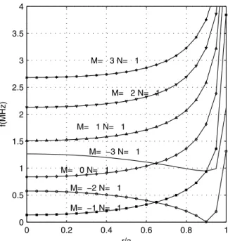
The frequency of theRF generator depends on the ra-dial position of the mode conversion zonerAand the excited
wave mode numbersM, Naccording to the dispersion
rela-tion ω2
RF =k
2
||(rA)CA2(rA)(1−ω2RF/ω
2
ci), (1)
where
k||(r) =
N R
1 + M
N q∗(r)
(2) Here we have used the effective safety factorq∗, which was
introduced in the MHD stability studies of the spherical to-kamaks [15, 16], q∗(r) = rBT
RBP(r)
1 +K2 2
,K is the vertical elongation,Ris the major radius of the plasma co-lumn, andris the radial coordinate of a pseudo-toroidal co-ordinate system centered at the magnetic axis,MandNare poloidal and toroidal wave numbers correspondingly.
The numerical simulation have been made for the fol-lowing ETE parameters:R0= 0.3m,a= 0.2m,B= 0.4T,
IP = 0.2MA,n0= 3×10¹⁹m−3,K= 1.6. The equations
forE⊥andB||, which determine excitation of fast Alfv´en
wave and its resonant absorption due to plasma inhomoge-neity, are solved for plasma column with parabolic density profile n = n0
(1−δ)1−r2
/a2
+δ, where a small density jump n0δ (δ =10−2 ;10−3 ) at the plasma
boun-dary is introduced in order to match bounboun-dary conditions and to avoid computational difficulties. Since the antenna system is designed for excitation of fast Alfv´en waves, this jump has no influence on calculated characteristics of an-tenna performance. The plasma current density is assumed to be of the form j = j0
1−r2
/a2
. The antenna im-pedance Za
M,N in the course of the excitation of the AW
with mode numbers M, N was determined by the relation Za
M,N = 2PM,N/Ia2, wherePM,N is theRF power input
through the modeM, N, andIais the antenna current.
0 0.2 0.4 0.6 0.8 1
0 0.5 1 1.5 2 2.5 3 3.5 4
M= −3 N= 1
M= −2 N= 1
M= −1 N= 1 M= 1 N= 1
M= 2 N= 1 M= 3 N= 1
M= 0 N= 1
r/a
f(MHz)
0 0.2 0.4 0.6 0.8 1 0
0.5 1 1.5 2 2.5 3 3.5 4
M= 0 N= 2 M= 1 N= 2 M= 2 N= 2
r/a
f(MHz)
M= 3 N= 2
M= −1 N= 2
M= −2 N= 2
M= −3 N= 2
Figure 2. Dependence of the AW frequency on the radial position of the resonance zone for the AW modes with toroidal mode num-berN = 2.
In the AW heating scheme, the waves are launched by an external antenna structure, which can define the toroi-dal wave numberN. However, because of toroidal mode coupling, the poloidal wave numberMis not uniquely defi-ned by the antenna structure. This feature will result in the simultaneousRF power deposition at different radial posi-tions. The calculations of the RF generator frequency for toroidal modesN = 1andN = 2are shown in Figs. 1, 2 correspondingly.
It is seen that many AW resonance zones can exist for given RF generator frequency at the same time, and in this caseRF power deposition zone can not be localized in the predefined plasma region. These calculations lead us to the conclusion that in order to decrease this effect the generator frequency has to be chosen as low as possible. The second conclusion, which can be made, is the need to guarantee the formation of monochromatic toroidal mode spectrum. The results of the AW antenna impedance calculations are shown in Fig. 3.
It is seen that the magnitude of the antenna impedance for the modes of interest is different, and this permits to find the optimal conditions for theRFsystem operation.
3
Antenna system of the ETE
3.1
Antenna structure
The design of the AW antenna system for the ETE tokamak has been done with regard to the already existing construc-tion of the vacuum chamber and the necessity to ensure the antenna mounting without major modifications of the exis-ting equipment. On the other hand the excitation of the
tra-velling waves has to be guaranteed. In this case the exci-tation of the monochromatic toroidal spectrum in the ETE tokamak with reasonable number of antenna straps can be accomplished with the eight antenna modules, which are installed in the four toroidal cross-sections of the vacuum chamber. The schematic representation of the proposed an-tenna structure is shown in Fig. 4 with the corresponding phasing of theRFfeeding currents.
1.4 1.6 1.8 2 2.2 2.4
0 0.5 1 1.5 2 2.5 3 3.5 4
M= −1 N= 2
M= 1 N= −2
M= −1 N= −1
f(MHz)
Za(Ohm) M= 1 N= 1
M=−1 N= −2
M=1 N= 2
Figure 3. Dependence of the impedance of ideal poloidal antenna on radial Alfv´en zone position for different Alfv´en modes.
Figure 4. Scheme of antenna straps positioning in the ETE and the phasing of the RF feeding currents for excitation of the mode M=-1, N=-1.
such sets of windings in four toroidal cross-sections of the vacuum chamber of the ETE. Such configuration of an an-tenna system permits to excite the predominating travelling Alfv´en mode withM=±1,N =±1. The direction of the wave propagation can be controlled by the corresponding phasing of the antenna feeding currents.
Figure 5. Schematical presentation of antenna construction for the ETE tokamak
The positioning of the antenna elements in the vacuum chamber of the ETE is shown schematically in Fig. 5. The design of the RF system for the ETE is based on model experiments that have been carried out in the TCABR to-kamak. The antenna modules are mounted on the vacuum flanges. The mounting of the antenna elements inside the vacuum chamber can be accomplished through the vacuum ports. The construction of antennae ensures protection from the direct antenna-plasma interaction in the form of side and front-end BN protectors. The four-phase RF generator with output power up to 1MW powers the antennae through the impedance matching units.
3.2
The impedance spectral characteristics of
the antenna system
The matching of theRF power generator with the antenna load requires the knowledge of antenna parameters in the working range of the operational parameters of the ETE to-kamak. In the low frequency range ofRFsystem operation (f = 1−3MHz) the antenna electrical scheme can be re-presented by the complex impedanceZ=Za+iZr, where
Zais responsible for theRF power dissipation both in the
plasma and in the antenna strap itself, andZris formed by
the antenna strap self inductance and by the inductance in-troduced by the coupling with the AW plasma oscillations. In the sequel we present the calculations of the part of the antenna impedance, which results from the AW dissipation in the plasma.
The procedure for the antenna impedance calculations consists of the following steps:
- representation of the real antenna geometry as a sum of basic current carrying straps;
- decomposition of the basic elementary current in heli-cal Fourier series ;
- finding field solutions of the boundary value problem for antenna currents , including also the corresponding ra-dial feeding currents;
- summing up the field harmonics with corresponding weight and finding the antenna impedances both for the sin-gleM,N mode excitation and for the total antenna delive-red power.
The geometry of a basic current carrying antenna ele-ment is shown in Fig. 6.
Figure 6. Scheme of one strap antenna current Fourier decomposi-tion.
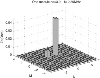
Since the total antenna impedance is formed by the con-tributions from the different AW modes, which ensureRF power input in the different plasma regions, we can analyze the conditions of the AW modes excitation in the different regimes of the AW system operation. The spectral contri-butions to the antenna module impedance, which is fed by the RF current at the frequencyf = 2.3MHz, are shown in Fig. 7. It is seen that a rather wide spectrum of the AW modes is excited. The main contribution to the antenna im-pedance is made by the modeM=−1, N=−1.
−5 0
5
−4 −2 0 2 4 0 0.01 0.02 0.03 0.04
N One module ne=3.0 f= 2.30MHz
M
Za(Ohm)
Figure 7. Partial spectral contributions to the antenna module im-pedance Za. The generator frequency isf = 2.3 MHz, n0 =
3×10¹⁹m−3
.
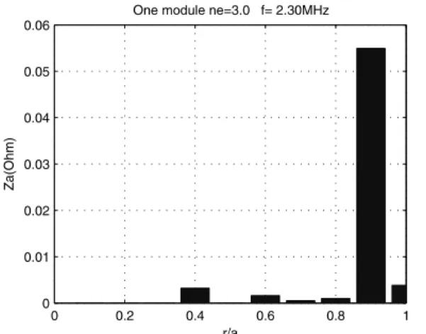
in the regions, which are close to plasma boundary. The ra-dial localization of theRF power input zones for this case is shown in Fig. 8.
0 0.2 0.4 0.6 0.8 1 0
0.01 0.02 0.03 0.04 0.05 0.06
r/a
Za(Ohm)
One module ne=3.0 f= 2.30MHz
Figure 8. Dependence of antenna module partial impedance on the plasma radius,f= 2.3MHz,n0= 3×10
19 m−3
.
−5 0
5
−4 −2 0 2 4 0 0.02 0.04 0.06 0.08 0.1 0.12
N Four modules ne=3.0 f= 2.30MHz
M
Za(Ohm)
Figure 9. Partial spectral contributions to the antenna module im-pedanceZa. The generator frequency isf = 2.3MHz, n0 =
3×10¹⁹m−3
. The antenna consists of four modules.
It is seen that the contribution of the modeM = −1, N =−1defines the total antenna impedance and makes it impossible to control the localization of theRFpower input in the predefined plasma region.
This situation can be improved if more antenna modu-les are activated. It has to be mentioned here that the AW excitation has a coherent nature, which makes it different, for example, from the electron cyclotron wave excitation. It means that the field amplitudes, which are excited by the all antennae, are summed, and that is why the activating of the additional antenna modules increases the antenna impe-dance as well. The spectrum distribution of the antenna im-pedance in the case, when all four modules are activated, is given in Fig. 9. The phasing of the feeding current was opti-mized in order to excite predominantly the modeM =−1, N =−2.
It is seen that theRFmode selection is better now, but nevertheless many additional modes are excited as well. The corresponding radial distribution of the RF power input is shown in Fig. 10. It is seen that the portion of theRFpower input in the inner part of the plasma column is higher now, but the RF power input at the plasma boundary is still high.
0 0.2 0.4 0.6 0.8 1 0
0.02 0.04 0.06 0.08 0.1 0.12 0.14
r/a
Za(Ohm)
One module ne=3.0 f= 2.30MHz
Figure 10. Dependence of the antenna module impedance on the plasma radius,f = 2.3MHz,n0= 3×10
19 m−3
. Four antenna modules are activated.
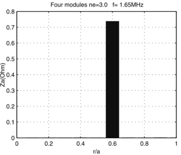
The profound changes in the possibility to control the localization of the RF deposition zone occur when the fre-quency is decreased, and the mode M=1, N=1 becomes prin-cipal. The spectrum distribution of the antenna impedance in this case is given in Fig. 11. It is seen that the main part of the antenna impedance is due to the excitation of the AW modeM= 1,N = 1.
−5 0
5
−4 −2 0 2 4 0 0.1 0.2 0.3 0.4 0.5 0.6 0.7
N Four modules ne=3.0 f= 1.65 MHz
M
Za(Ohm)
Figure 11. Partial spectral contributions to the antenna module impedance Za. The generator frequency is f = 1.65 MHz,
n0 = 3×10 19
m−3
0 0.2 0.4 0.6 0.8 1 0
0.1 0.2 0.3 0.4 0.5 0.6 0.7 0.8
r/a
Za(Ohm)
Four modules ne=3.0 f= 1.65MHz
Figure 12. Dependence of the antenna module impedance on the plasma radius,f= 1.65MHz,n0= 3×10
19 m−3
. Four antenna modules are activated.
2
2.5 3 3.5
4
0 0.5
1 0 0.2 0.4 0.6 0.8 1 1.2 1.4
no r/a
Za(Ohm)
Figure 13. Radial dependence of theRFpower input localization on the plasma central density. The antennae are formed by four modules. TheRF generator frequency is 1.65 MHz.
The corresponding radial distribution of the RF power input is shown in Fig. 12.
It is seen that the localization of the power deposition area is completely controlled by the AW system.
The dependence of the RF power input localization on the plasma density for this case is shown in Fig. 13. It is seen that the area of the RF power input is well controlled both by the AW system regime and by the plasma discharge parameters.
0 0.05
α= −15
0 0.05
α= −10
0 0.05
α= −5
0 0.05
α= 0
0 0.05
α= 5
0 0.05 0.1
α= 10
0 0.2 0.4 0.6 0.8 1 0
0.05 0.1
α= 15
r/a Za(Ohm)
Figure 14. Dependence of the radial distribution of theRFpower input on the inclination angleαof the antenna straps. The angular magnitude ofαis given in degrees.
The further improvements in the selectivity of the AW mode excitation and in the increasing of the antenna-plasma coupling can be obtained by an inclination of antenna straps in the toroidal direction, as is shown in Fig. 6. The calcula-ted dependence of the radial distribution of the RF power in-put on the inclination angleαis shown in Fig. 14. It is seen that the antenna strap inclination in a rather narrow range of angles (α = 10−15◦) permits to redistribute theRF
power input between the different AW modes, to decrease the power input at the plasma periphery, and to increase the antenna impedance. The design of the AW antenna for the ETE spherical tokamak provides the possibility to carry out the experiments on the comparative study of different an-tenna configurations and inclination angles.
4
Conclusion
The RF system of the ETE tokamak was designed with the objective to ensure both the effective plasma heating and the non-inductive current drive. In the course of the RF system design the results of the experiments on the Alfv´en wave heating and current drive, which were carried out in the TCABR tokamak, were used. The proposed RF system in-corporates components and technical solutions, which were tested and approved in the course of the design and exami-nation of the RF system of the TCABR tokamak.
of antenna straps, of the antenna feeding phasing and of the antenna inclination angles were studied.
The analysis of the AW antenna system implementation for the ETE spherical tokamak, which is presented in this work, has to be considered as the first preliminary step for the more detailed future design. The physical processes, which accompany the AW excitation in the spherical toka-mak, are much more complicated, and have to be analyzed in 2-D computational models. This work outlines only the questions, which have to be analyzed more thoroughly later.
Acknowledgments
The authors wish to acknowledge helpful discussions with G. O. Ludwig, E. Del Bosco, and A. G. Elfimov. This work has been supported by The National Council for Scien-tific and Technological Development CNPq, and The State of S˜ao Paulo Research Foundation FAPESP.
References
[1] J. R. Wilson, R. E. Bell, S. Bernabei M. Bitter, P. Bonoli, D. Gates, J. Hosea, B. LeBlanc, T.K. Mau, S. Medley, J. Menard, D. Mueller, M. Ono, C.K. Phillips, R.I. Pinsker, R. Raman, A. Rosenberg, P. Ryan, S. Sabbagh, D. Stutman, D. Swain, Y. Takase, and J. Wilgen, Phys. Plasmas10, 1733 (2003).
[2] S. Cuperman, C. Bruma, and K. Komoshvili, Phys. Letters A 311, 221 (2003).
[3] A. Hasegava and L. Chen, Phys. Fluids19, 1924 (1976).
[4] A. G. Elfimov, 2nd Joint Grenoble-Varenna Int. Symp. on He-ating in Toroidal Plasmas, Como, Italy, 683, (1980).
[5] D. W.Ross, G. L.Chen and S. M. Mahajan Phys. Fluids,25, 652 (1982).
[6] K. Appert, R. Gruber, F. Troyon, and J. Vaclavik, Plasma Phys.24, 1147 (1982).
[7] K. Appert, G.A. Collins, F. Hofmann, R. Keller, A. Lietti, J.B. Lister, A. Pochelon, and L. Villard, Phys. Rev. Lett.,2, 1671 (1985).
[8] J. Vaclavik and K. Appert, Nucl. Fusion,31, 1945 (1991).
[9] G. Amarante-Segundo, A. G. Elfimov, D. W. Ross, R. M.O. Galvo, and I. C. Nascimento, Phys. Plasmas,6, 2437 (1999).
[10] S. A.Galkin, A. A. Ivanov, S. Yu. Medvedev, and A. G. Elfi-mov, Comp. Phys. Communications,143/1, 29 (2002).
[11] K. G. McClements, L. C. Appel, M. J. Hole, and A. Thyaga-raja, Nucl. Fusion42, 1155 (2002).
[12] L. F. Ruchko, M. C. Andrade, R.M.O.Galv˜ao, Nuclear Fusion 36, 503 (1996).
[13] K. Appert, J. Vaclavic, and L. Villard. Introduction to the the-ory of Alfv´en wave heating. Lausanne, CRPP, report LRP 238/84, 1984.
[14] D. W. Ross, Y. Li, S. M. Mahajan, R. B.Michie, Nuclear Fu-sion26, 139 (1986).
[15] T. C. Hender, S. J. Allfrey, R. Akers, L.C. Appel, M.K. Be-vir, R.J Buttery, M. Gryaznevich, I. Jenkins, O.J. Kwon, K.G. McClements, R. Martin, S. Medvedev, M.P.S. Nightingale, C. Ribeiro, C.M. Roach, D.C. Robinson, S.E. Sharapov, S. Sykes, L. Villard, and M.J. Walsh, Phys. Plasmas,6, 1958 (1999).