Abstract
This paper deals with Finite Element refined and simplified mod-els of a mild steel spot-welded specimen, developed and validated based on quasi-static cross-tensile experimental tests. The first model was constructed with a fine discretization of the metal sheet and the spot weld was defined as a special geometric zone of the specimen. This model provided, in combination with experimental tests, the input data for the development of the second model, which was constructed with respect to the mesh size used in the complete car finite element model. This simplified model was developed with coarse shell elements and a spring-type beam ele-ment was used to model the spot weld behavior. The global accu-racy of the two models was checked by comparing simulated and experimental load-displacement curves and by studying the speci-men deformed shapes and the plastic deformation growth in the metal sheets. The obtained results show that both fine and coarse finite element models permit a good prediction of the experimental tests.
Keywords
Mild steel; Spot weld; Cross-tensile specimen; Quasi-static test; FEM.
Finite Element Method Based Modeling
of Resistance Spot-Welded Mild Steel
1 INTRODUCTION
Resistance Spot Welding is a widely used process of joining metal sheets in the automotive industry with at least 2000 to 5000 Resistance Spot Welds (RSW) in a typical car body. The failure of these spot welds significantly affects the deformation behavior of auto-body structures (Abadi and Pouranvari. 2014; Pouranvari and Marashi. 2013). Therefore, it is of high importance to understand their strength and failure mechanism under quasi-static, impact, and fatigue loading conditions for the vehicle performance assessments and crashworthiness. In this paper, we focus our attention on the failure behavior of spot welds under quasi-static loading condition.
Miloud Zaoui a,* Abdelhamid Hadjoui a
a Department of Mechanical Engineering,
Faculty of Technology, Abou Bekr Belkaid University of Tlemcen, 13000, Algeria
* Corresponding author’s e-mail:
[email protected] Tel. +213 555 797 807 Fax: +213 48 65 30 41
http://dx.doi.org/10.1590/1679-78252978
In automotive crash testing, comparisons between numerical results and experiments have shown that the main source of results’ dispersion is due to a bad prediction of the mechanical be-havior and fracture of spot-welded structures or other joining techniques (Lamouroux et al. 2007).
Over the past few decades, various finite element (FE) models of spot welds have been proposed for static and dynamic structural analysis (Palmonella et al. 2005; Radakovic and Tumuluru. 2012). Each of these FE models has its individual characteristics and advantages or disadvantages. Gener-ally, in a full-scale structural analysis, relatively simple models are used in the automotive industry since it is the global effect of the spot welds on the deformation shape of the welded parts, which is of interest and not their local behavior. From an industrial point of view, the major requirement of these spot weld models is to yield accurate predictions in a short modeling time.
To verify the prediction of the FE simulations, research also focused on experimental studies on the spot weld mechanical properties. For that purpose, lap-shear, coach-peel and cross-tension tests have been elaborately performed to estimate the failure characteristics of the spot weld (Abadi and Pouranvari. 2014; Radakovic and Tumuluru. 2012; Pouranvari et al. 2015; Chao. 2003a; Chao. 2003b; Zuniga et al. 1997; Lin et al. 2003; Marya et al. 2006; Lin et al. 2002). For example, Chao (2003a) studied the ultimate tensile strength of resistance spot welds in mild steel subjected to com-bined loading tension and shear loads, and verified that a spot weld under cross-tensile loading fails at a lower load than a spot weld subject to lap-shear loading. The failure modes of the RSW of advanced high-strength steels were investigated by Abadi and Pouranvari (2014) under tensile-shear, coach-peel and cross-tension tests. Their results show that the tendency to fail in the interfa-cial mode is highest in the tensile-shear loading condition, while the cross-tension test exhibits a higher tendency to fail in the pullout failure mode.
The objective of this paper was to investigate the strength and the failure mechanism of RSW in mild steel based on quasi-static cross-tensile experimental tests and 3D finite element analysis.
2 MATERIALS AND METHODS 2.1 Specimens and Quasi-Static Tests
Cross-tensile specimens of XES commercial mild steel were used. Assuming plastic hardening of metals is specified by the stress–strain curve in the form σy (p) = σ0 + Kpn, the material properties
and the parameters σ0, K and n are given in Table 1. In accordance with the EN ISO 18278-2
standard (ISO. 2004), these specimens are composed of two 38mm wide by 125mm long plates spot-welded at the middle of overlap region as shown in Figure 1. The RSW has 5mm nominal diameter and both the top and bottom sheets have the same thickness of 1.17mm. Resistance spot welding was performed using a static 50Hz machine according to the EN ISO 18278-2 standard (ISO. 2004). The welding parameters are summarized in Table 2.
E (MPa) ν σ0 (MPa) Rm (MPa) Ag (%) K (MPa) n
210000 0.3 54.80 297 26 412.95 0.241
Electrode force (kN)
Number of pulses
Welding time (cycles)
Holding time (cycles)
Welding current (kA)
3 1 12 12 7.5
Table 2: Welding parameters for the XES steel sheets.
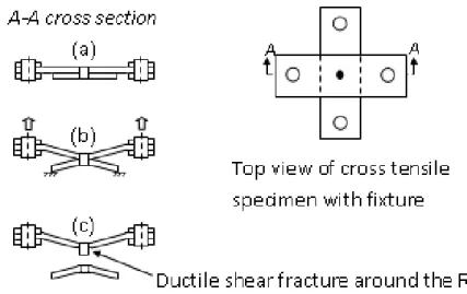
Figure 1: The cross-tensile specimen.
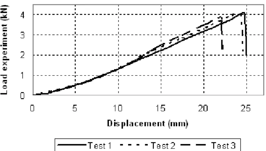
Quasi- static tests of cross-tensile specimens were conducted at low velocity (10mm/min) using a MTS Sintech 20D tensile testing machine. The Failure process of cross-tensile specimen is shown in Figure 2. The bottom plate is clamped and the top plate is submitted to displacement-controlled conditions. From these tests, general load-displacement curves were recorded. Figure 3 shows typi-cal load-displacement curves of three replicate quasi-static tests.
Figure 3: Load-displacement curves of three cross-tensile specimen tests.
2.2 Finite Element Modeling
Accurate predictions of the RSW behavior can be obtained only when realistic link models are used. However, the complexity of physical phenomena related to the welding process, the large number of spot welds in the car body-in-white and the mesh size used in the car FE-models prevents to have a fine FE-representation of each RSW. Accordingly, a coarse model of RSW should be defined as a compromise between modeling requirements and a good representativeness of the link element. For an optimal transition from the fine to the coarse model, it is necessary to determine the RSW effect on the plate’s deformation, especially in the strongly loaded zones surrounding the RSW. In par-ticular, for the quasi-static analysis of spot welded structures, the model should be able to accurate-ly predict the strength and failure of the RSW and consequentaccurate-ly the stiffness of the structure.
2.2.1 Definition of the Models
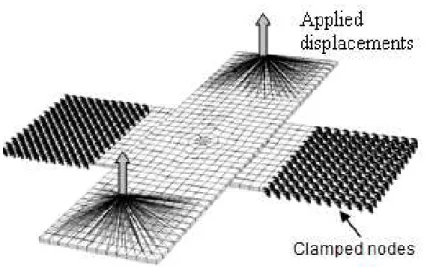
Our study is based on two finite element models constructed in the commercial FE-code ABAQUS: in the first one (Figure 4), fine solid-FE having sides of 3mm were used to mesh the metal sheets and the RSW was taken into account as a special geometric zone of the specimen. The bottom plate was clamped and a vertical displacement was applied at the two opposite sides of the top plate. Two regions of 30mm x 38mm were used to clamp the bottom plate, where two other regions with the same dimensions were used to apply the controlled displacements. The large grey arrows in Figure 4 schematically show the direction of the applied displacements.
Figure 4: Fine model of cross-tensile test.
Figure 5: Coarse model of the cross-tensile test.
2.2.2 Elastoplastic Equations of the Models
2.2.2.1 Elastic Behavior
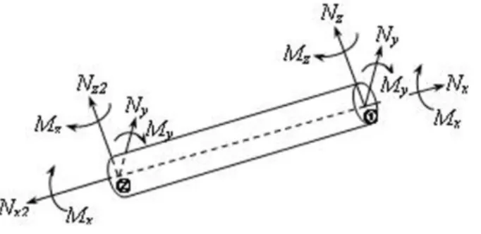
Figure 6 shows a circular cross-section of the FE-beam considered in modeling the RSW. The beam of length L and section S, was assumed to have a Young’s modulus E, the bending inertia I, the torsion inertia J, and the shear modulus G. All of these entities were defined in the local coordinate system xyz which is fixed on the center of gravity of the beam. In the forces resultant theory, each end of the beam is subject to the resultant vector R, which is defined as R = {Nx Ny Nz Mx
My Mz}, where Nx, Ny, Nz are the normal force and the two shear forces, respectively, and Mx, My,
Figure 6: Conventions of beam element.
The expression of the elastic strain energy per unit of length in the local coordinate of the beam can be written as equation (1) where Sr is the reduced section due to the shear load:
2
U
def
M
y 2
M
z2
EI
M
x2GJ
N
y2
N
z2GS
r
N
x2ES
(1)In practice, for massive beams the section Sr differs little from the section S. For this reason,
the calculation of deformation due to the shearing force is often performed taking into account S instead of Sr. The exact calculation is established by using the strain energy due to the shear load
(MacNeal and Harder. 1985).
Then, Hooke's law is written in generalized entities: g
E gWhere {σ}g and {ε}g are respectively the generalized stress and strain vectors. The elasticity
matrix [E] is defined by:
E
Cm
00
Cf
and
Cm
E 0 0
0 2G 0 0 0 2G
, Cf
G 0 0
0 E 0 0 0 E
2.2.2.2 Plastic Behavior
A quadratic yield surface could be defined as a criterion for predicting the elastoplastic hardening in terms of generalized loads which are assumed to be uncoupled. For this purpose, we chose the crite-rion proposed by Ilyushin (1956) and developed and generalized by Crisfield (1974). In our study, this criterion was written as follows:
F2
p Nx N0
23 Ny
N0
2
3 Nz
N0
2 Mx
M0
2 My
M0
2
Mz
M0
2
2
p(2)
where N0 and M0 are the load and the moment for which the plasticity may be started. γ(p) is a
function of the material’s hardening based on the normalized stress–strain curve in a form adapted for an optimization procedure such as Ludwig’s law equation (3):
y(p)0Kpn and
(p)
y(p)σ0 is the yield stress, p is an internal variable to model the material’s hardening, K and n are
pa-rameters of the Ludwig’s law.
The generalized stress vector being defined by:
g N M Criterion equation (2) can be written: F2(p) N M t
F(p)
NM
2(p)
Or in a more general form:
f tg
F gy2 0 (4)Thus, the generalized equivalent stress can be written as:
eq
gt
F g in which [F] isthe following matrix:
F
Am
00
Af
and
Am
1 0 0 0 3 0 0 0 3
, Af
1 0 00 1 0 0 0 1
The generalized plastic strains vector is calculated simply by using the normality rule equation (5):
d
p
g f
gd
(5)The equivalent plastic strain p is defined as being proportional to the plastic deformation ener-gy:
{ }
{ }
g t
ydp d p g
s = s e
Combining equations (4) and (5) leads to:
dp2
g
t
F
gd
/
y2
yd
Finally, the problem amounts to solving the following system of equations:
d
g
E ({d
}g{d
p}g)f
tg
F
g
y20d
p
g f
gd
and df 03 RESULTS 3.1 Failure Mechanism
Our tensile test results are consistent with experimental observations reported in the literature (Abadi and Pouranvari. 2014; Radakovic and Tumuluru. 2012; Chao. 2003a; Zuniga et al. 1997; Lin et al. 2003) and reveal the pullout failure process of the cross-tensile specimens as schematically demonstrated in Figure 2. Generally, when the load is applied, both plates undergo an initial global deflection until the intense plastic deformation occurs near the circumferential surface of the RSW. When the peak load is reached, the RSW may fail in two distinct modes: the interfacial failure and the pullout failure. In the interfacial mode, a failure occurs via a crack propagation, while, in the pullout mode, a failure occurs via a nugget withdrawal from one sheet. The pullout mode is the generally preferred failure mode due to its high load-carrying capacity and energy absorption capa-bility. However, when the spot weld process is inaccurate or the expected deterioration of spot welds quality occurs during the product lifetime, spot welds may have the interfacial failure mode as discussed by Chao (2003a, 2003b) and Lin et al (2003). It has been proved that the sheet thick-ness and the weld diameter are the two primary factors influencing the failure mode of the RSW. Therefore, the interfacial failure mode can be largely eliminated by controlling the welding process (Pouranvari and Marashi. 2013; Pouranvari et al. 2015; Chao. 2003a; Chao. 2003b; Zuniga et al. 1997; Lin et al. 2003; Marya et al. 2006).
3.2 Deformed Shape and Load-Displacement Curves
Figures 7 and 8 show a typical deformed shape of the fine and coarse cross-tensile models at a dis-placement of 19.5 mm. The top plate begins to deform before the bottom plate and when the load continues to increase, both plates present symmetric deformations about the interface. These obser-vations are confirmed by the experiment.
Figure 8: Deformed shape of the coarse cross-tensile model (D= 19.5 mm).
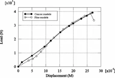
In our study, the strength of the RSW was characterized by studying the load-displacement curves of the specimens. As shown in Figures 9 and 10, the obtained computational load-displacement curves are in good agreement with the experimental curves.
Figure 9: Load-displacement curve of the fine model, comparison with the experiment.
Analysis of these curves highlights the existence of two phenomena in competition: plastic de-formation and geometric stiffening. Beyond an initial linear portion corresponding to the elastic behavior, the curve remains linear in the plastic portion until the maximum load, which is consid-ered as the failure load. Indeed, when the displacement continues to increase, the load starts drop-ping gradually as the crack initiation occurs followed by its propagation along the circumference of the nugget as discussed by Lin et al. (2002, 2003). However, in order to bring down these curves in the FE-model, a failure criterion must be introduced. Some failure criterions were proposed in the literature to investigate the failure load of spot welds. Pouranvari and Marashi (2013) critically review some of them. Moreover, spot welds in structural components often fail under combined loads during vehicle crashes; a general failure criterion for spot welds under combined loads will be then helpful for the crashworthiness analysis in the early automotive design stage.
3.3 Plastic Deformation
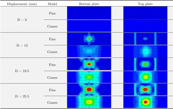
The study of the plastic deformation is helpful to determine the strongly loaded regions of the metal sheets where the failure is probable. Table 3 shows the plastic deformation growth in the fine and the coarse cross-tensile models. Maximum plastic deformation occurs in the circumferential surface of the weld when the displacement corresponds to the failure load. Moreover, the computation indi-cates that the rigidity of the spring-type beam element has two major influences: it increases the slope of the curve and supports the geometrical rigidity compared to the plastic deformation of the material.
Displacement (mm) Model Bottom plate Top plate
D = 0
Fine
Coarse
D = 13
Fine
Coarse
D = 19.5
Fine
Coarse
D = 25.5
Fine
Coarse
4 CONCLUSIONS
Quasi-static cross-tensile experimental tests and FE-analysis presented in this paper were performed to investigate the strength and the failure mechanism of spot-welded mild steel. The global accura-cy of the proposed refined and simplified FE-models was checked by comparing simulated and ex-perimental load-displacement curves and by studying the specimen deformed shapes and the plastic deformation growth in the metal sheets. The obtained results show a good agreement between the two models and experiments.
References
Abadi, M.M.H., Pouranvari, M., (2014). Failure-mode transition in resistance spot welded DP780 advanced high-strength steel: effect of loading conditions. Materiali in tehnologije / Materials and technology 48(1), 67-71.
Chao, Y.J., (2003a). Ultimate strength and failure mechanism of resistant spot weld subjected to tensile, shear, or combined tensile/shear loads. Journal of Engineering Materials and Technology 125(2), 125-132.
Chao, Y.J., (2003b). Failure of Spot Welds: Interfacial versus Pullout. Science and Technology of Welding and Join-ing 8(2), 133-137.
Crisfield, M.A, (1974). On an Approximate Yield Criterion for Thin Steel Shells. TRRL Report LR658, Transport and Road Research Laboratory, Crowthorne, Berkshire, UK.
Ilyushin, A.A, (1956). Plasticité (in French), Edition Eyrolles, Paris.
ISO (2004). "Resistance welding – weldability. Part 2: Alternative procedures for the assessment of steel sheets for spot welding", ISO 18278-2:2004E, ISO, Geneva, Switzerland.
Lamouroux, E.H.J., Courtellier, D., Doelle, N., Kuemmerlen, P. (2007). Detailed model of spot- welded joints to simulate the failure of car assemblie. International Journal for interactive design and manufacturing 1, 33-40.
Lin, S.H., Pan, J., Tyan, T., Prasad, P., (2003). A general failure criterion for spot welds under combined loading conditions. International Journal of Solids and Structures 40(21), 5539-5564.
Lin, S.H., Pan, J., Wu, S., Tyan, T., Wung, P., (2002). Failure loads of spot welds under combined opening and shear loading conditions. International Journal of Solids and Structures 39, 19-39.
MacNeal, R., Harder, R., (1985). A proposed standard set of problems to test finite element accuracy. Finite ele-ments in analysis and design 1, 3-20.
Marya, M., Wang, K., Hector Jr, L.G., Gayden, X.Q., (2006). Tensile-shear forces and fracture modes in single and multiple weld specimens in dual-phase steels. Transactions of the ASME Journal of Manufacturing Science and En-gineering 128(1), 287-298.
Palmonella, M., Friswell, M.I., Mottershead, J.E., Lees, A.W., (2005). Finite element models of spot welds in struc-tural dynamics: review and updating. Computers and Structures 83, 648-661.
Pouranvari, M., Marashi, S.P.H., (2013) Critical review of automotive steels spot welding: process, structure and properties. Science and Technology of Welding and Joining 18(5), 361-403.
Pouranvari, M., Marashi, S.P.H., Jaber, H.L., (2015). DP780 dual-phase-steel spot welds: critical fusion-zone size ensuring the pull-out failure mode”. Materiali in tehnologije / Materials and technology 49(4), 579-585.
Radakovic ,D.J., Tumuluru, M., (2012). An Evaluation of the Cross-Tension Test of Resistance Spot Welds in High-Strength Dual-Phase Steels. Welding Journal 91, 8s-15s.