STUDY OF Al/CAST IRON INTERFACE AND GRAPHITE BEHAVIOR
M. Akbarifara, M. Divandaria*
a Iran University of Science and Technology, Materials Engineering, Tehran, Iran
(Received 08 January 2016; accepted 25 October 2016)
Abstract
The interface characteristics of aluminum/cast iron bimetals produced by compound casting were investigated. Aluminum melt was poured into molds, at 700 ̊C and 750 ̊C, around cylindrical cast iron bars having melt-to-solid volume ratios (Vm/Vs) of 3, 5 and 8, respectively. Microscopic observations showed that a reaction layer may form at the interface. This layer is composed of Fe2Al5intermetallic which has been formed initially at the notches of the insert’s surface after making contact with the molten metal. The thickness of the interaction layer varied from 5μm, for the sample produced at 700 ̊C and 3 Vm/Vs, up to 20μm for the sample poured at 750 ̊C and 8 Vm/Vs. Microstructural analysis showed that increasing of the temperature and the melt-to-solid (m/s) volume ratio leads to the formation of a thicker and more uniform intermetallic layer. Microhardness of the Fe2Al5compound was measured 824 HV. A mechanism is suggested for the nucleation and growth of this intermetallic layer and also encapsulation of the flake graphite at the interface of two metals. It seems that the thermal and chemical situation at the interface of two metals, leads to an acceptable wettability of the graphite by molten aluminum.
Keywords:Aluminum; Cast Iron; Interface; Al-Fe Intermetallic; Graphite encapsulation
* Corresponding author: [email protected]
S e c t i o n B : M e t a l l u r g y
DOI:10.2298/JMMB160108027A 1. Introduction
Using aluminum/cast iron (Al/C.I.) couples is a matter of interest in automotive industries because of the high strength/weight ratio of aluminum. There have been reports on using the cast iron cores in order to reinforce the aluminum made pistons [1,2]. Furthermore, cast iron has become a suitable liner to place in the aluminum alloy cylinder blocks, in order to provide the wear resistance needed in the area [3]. Numerous ways such as diffusion bonding [4-12], friction stir welding [13-19], laser beam welding [20-22], brazing [23,24] and other mechanical welding methods [25-28] have been developed to produce metallic couples. Factors like shape, geometry and size of the bimetal, differences in characteristics of the selected metals, special equipment and tooling are restrictions of using aforementioned methods [29,30]. However, there are some interests in casting, as a suitable technique for bimetals production, which provides the ability of joining metals regardless of the size and complexity of the geometry.
Compound casting is a method for producing various components in which a metallic melt is poured into or around a solid metal to form an acceptable bonding at the interface [31-33].
Therefore, it would be important to study the interface structure and characteristics of two metals and the effects of various parameters on the interface. Entering the mold cavity, the molten metal has a high amount of thermal energy, which can provide the activation energy for the consequent interactions at both sides of the melt/insert interface. Accordingly, any changes in the casting temperature and the liquid/solid ratio can alter the condition at the interface [34-39]. Previous investigations on the aluminum/brass (Al/Brass) by authors, proved the effectiveness of the variation of the pouring temperature and melt-to-solid (m/s) volume ration on the characteristics of the interface between two metals [39]. As the solidification process begins, because of the interactions between two metals in the presence of thermal energy in use, intermetallic compounds can be formed [12]. In the case of Fe-Al system, these compounds are brittle and have the ability to deteriorate the mechanical properties of the interface. Apart from that, the wettability of graphite flakes with molten aluminum can be a challenge. Omrani et.al explain that the contact angle between aluminum and graphite is high enough to be an obstacle and hinder the process [40-41].
study the characteristics of Al/cast iron couples’ interface in various pouring temperatures and m/s volume ratios.
2. Experimental
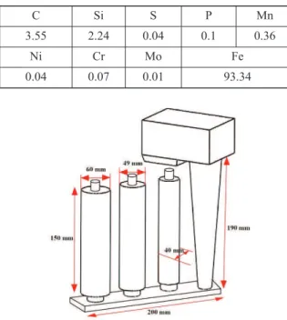
Six grey cast iron bars, with 20 mm in diameter and 200 mm in height, were used as inserts. The composition of the insert bars is given in Table 1. The surfaces of the bars were processed by polishing them up to a 1500-grit and degreasing before inserting them into position within the molds. The gating system was designed in such a way to fill all cavities simultaneously (Fig. 1).
Commercially pure aluminum (99.9%) was poured into two CO2 sodium silicate sand mold cavities with 40, 49 and 60 mm diameters cylinder, respectively, first at 700˚C followed by the second pouring at 750˚C. Cast iron bars were situated in the center of each cavity.
After solidification, the bimetal cast bars were sectioned transversely through the bond, and the main part of each sample was selected for further investigations. Cross sections were numbered as shown in Table 2, and then they were prepared by grinding with 2500-grit paper and polished with 0.1μm alumina powders. The surfaces were etched by Nital solution.
Microstructural analysis of the samples were conducted using an optical microscope and Vega IITescan scanning electron microscope (SEM)
equipped with energy-dispersive spectroscopy (EDS). Finally, micro-hardness measurements were taken using a MHV-100Z-SCTMC hardness tester.
3. Results and discussion
The microstructure of the sample C700-3 is presented in Fig 3.a. It seems that the heat content of the molten metal was not enough, in this case, to dissolve the prominent points of the insert’s surface. Therefore, no discernible interaction products were found at the interface. However, the interface seems quite flawless and a mechanical bond has possibly been formed between the two metals; wetting of the solid surface by molten metal is required for such a condition. Unlike the other cases, for instance Al/ Cu bimetal [30], no clear effects of aluminum oxide films were detected at the interface of two metals. This might be a result of reduction characteristics of graphite in the cast iron structure.
With an increase in the melt/solid volume ratio (Vm/Vs), some compounds are formed at the interface (Fig 3.b and c). Continuity of this layer increases with the increase of Vm/Vs, and its average width changes from 8.5 μm, in sample C700-5, up to 13.5 μm in sample C700-8. Interestingly, while the thermal energy of the melt led to dissolving of the so called prominent points at the solid surface, the graphite is holding its position and encapsulated by the new intermetallic phase.
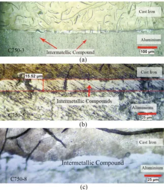
Fig. 4 shows the interface of the samples produced at 750 ̊ C with different m/s volume ratios. Clearly, the
C Si S P Mn
3.55 2.24 0.04 0.1 0.36
Ni Cr Mo Fe
0.04 0.07 0.01 93.34
Table 1. Chemical composition of the cast iron inserts used in this work (wt.%)
Figure 1. Schematic drawing of gating system
Sample No. Pouring
temperature M/S Volume Ratio
C700-3 700 ̊C 3
C700-5 700 ̊C 5
C700-8 700 ̊C 8
C750-3 750 ̊C 3
C750-5 750 ̊C 5
C750-8 750 ̊C 8
Table 2. Experimental samples investigated in this work
thickness of the intermetallic layer is increased in comparison to the samples produced at the lower temperature. The average thickness of this layer alters from 14 μm, in sample C750-3, to 15.5 and 19.5 μm in sample C750-5 and sample C750-8, respectively.
The corrugated nature of the interface (Fig 4.c) can be explained by the surface melting, the constitutional under-cooling caused by insert’s elements entering the melt and the formation mechanism of the intermetallic layer. Referring to the graphite position in Figs. 3 and 4, it can be seen that the melt/solid interface is moved toward the cast iron bar while their positions are intact. So, it is obvious that the formation of this layer is dominated by dissolving the iron from the insert into the molten aluminum.
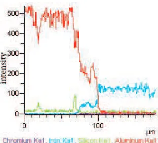
The intermetallic layer, formed at the interface of two alloys, can be seen in Fig. 5. EDS analysis of this layer shows a composition of 69.98 at. % Al and 30.01 at. % Fe (Fig. 6) which is identical to Fe2Al5 composition. In the binary Fe-Al system, FeAl3, FeAl2 and FeAl as well as Fe2Al5 are the stable intermetallic compounds at the temperatures below 750˚C [42]. FeAl3, FeAl2and FeAl compounds were not observed in any temperatures and m/s volume ratios in the present study. Probably, these three phases cannot grow to the visible thicknesses within this experimental conditions. Elemental distribution map for the interface of the sample C750-8 is presented in Fig. 7. Intensity of aluminum peak quickly falls to zero near the cast iron insert, while intensity of Fe peak increases in the solidified aluminum. The thickness of the reaction layer is about 27 μm including the region where both Al and Fe exist simultaneously.
Fig. 8 shows the SEM image of sample A700-3. Despite the fact that there is no visible evidence of any compound layer in Fig. 3, there are particles with average diameter of 5 μm grown at the areas with Figure 3. Optical micrographs of the interface layer in
samples produced at 700˚C with m/s volume ratios of a)3, b)5 and c) 8
Figure 4. Optical micrographs of the interface layer in samples produced at 750 ˚C with m/s volume ratios of a) 3, b) 5 and c) 8
higher surface roughness than nearby regions. It seems that the intermetallic layer, observed in the samples produced at the higher temperatures and m/s volume ratios, are formed by the growing, joining and overlapping of these particles. Similar observations are reported in literatures [43-44].
As the melt enters into mold cavity, it begins to dissolve insert’s surface. The effect of pouring temperature and m/s volume ratio is presented in Fig. 9. As it is expected, surface melting is mostly occurred in the lower parts of the inserts due to the higher temperature of the melt at the initial moments of filling. There is no sign of the surface melting in the middle and upper parts of sample C700-3 and sample C700-5 as is indicated in Fig. 9. However, it seems that the thermal energy of melt was not sufficient to dissolve more than 1 mm of the solid’s surface in almost all cases. Similar observations are reported for the Al/Brass couples [39].
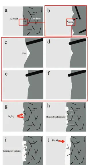
When the solid cast iron comes in contact with the molten aluminum, it starts to dissolve and form a Fe-Al intermetallic layer. Firstly, melt has to wet the surface of C.I. insert in order to form a sound and uniform interface. Despite conducting surface preparation of the inserts before putting them in the mold, they still may have notches which impede melt from touching their concaved ends (Fig. 10.b). This gap between the melt and the bottom of notches is possibly filled with the gases and should be eliminated in some way (Fig. 10.c). As the process continues, the prominent points start to dissolve into the molten metal and, the size of notches changes (Fig. 10.d and e). Finally, melt succeeds contacting the bottom of notch and aforementioned gases disappear from the interfacial area (Fig. 10.f). Therefore, wetting between melt and insert occurs successfully. Moreover, this leads to emergence of Fe rich regions, right behind the interface, which are suitable sites for the formation of intermetallic compound. The gas may either escape out, while the melt is coming up in the mold, or entrapped in the melt and/or participate in dissolving and also possible compound formation in the interface. Based on the Figure 6. EDS analysis of intermetallic layer in Fig. 5
Figure 7. Elemental distribution map at the interface of sample C750-8
Figure 8. SEM micrograph of sample A700-3 interface; Fe2Al5particles can be seen at the interface
Figure 9. Diagram of insert diameter after the
previous studies, formation of Fe2Al5 and FeAl3 intermetallic are expected as an interfacial reaction product [45-46], but, only Fe2Al5 was clearly observed at the interface. From the thermodynamic point of view, formation of FeAl3 is more possible because of the lower Gibbs energy of formation. In contrary to the thermodynamic principles, results proved the existence of Fe2Al5at the interface of two metals. Crystallographic defects in Al structure, leading to the high growth rate of Fe2Al5phase, is the main reason of appearing this phase instead of FeAl3
as Shahverdi et al. are asserted [45]. Vast numbers of vacancies along the axis of this phase with the orthorhombic structure offered a rapid diffusion path along [001] direction [47]. In other words, kinetics overcomes thermodynamics.
Apart from that, regarding the existence of Si in the composition of cast iron inserts, Yin et al. have discussed the Si’s role in reducing the activation energy of Fe2Al5, and decreasing the growth rate of FeAl3 [48]. Some other works have also reported the formation of Fe2Al5at the interface of Fe/Al in lower temperatures [47, 49-50]. Initial particles of Fe2Al5 nucleate at the indents (Fig. 10.g). This compound forms by the conventional way, i.e. nucleation and growth through the following reaction:
2Fel+ 5All= Fe2Al5s
Where the reactants are in liquid state in the vicinity of the insert and the product is in the solid form. In the next step, the nucleuses grow and join together by further precipitation from the melt and also diffusion of the Fe atoms toward this phase (Fig. 10.h). By combination of these new formed phases, further growth and overlapping of individual indents, a corrugated intermetallic layer forms (Figs. 10.i and j). It is worth to mention that Si prevents this phase from a completely preferential growth occupying vacancies in the c-axis of Fe2Al5structure [48]. With an increase in the solidification time, this layer can be more uniform and thicker. Moreover, interactions like the Fe transformation between the molten metal and the solid insert affect the solidification and the corrugation nature of the interfacial layer [45].
Fig.11 shows the schematics of graphite encapsulation by aluminum at the interface of two Figure 10. Schematic picture of intermetallic layer
formation at the interface of Al-C.I.
a)Inserts’ surface in touch with the molten aluminum
b)Air gap between the melt and the solid surface c)Melting of bulge areas and dissolvation of insert’s surface into Al melt
d)Complete wetting of solid surface e)Fe2Al5nucleates at the indents of surface f)Identical growth of the nucleases g) oining of the indents
h) - l) Overlapping and formation of a uniform intermetallic layer at the interface
Figure 11. Schematic picture of graphite’s encapsulation at the interface of Al-C.I.
a) Solvation of the insert’s surface in touch with the molten aluminum
b) Melt touches the graphite and tries to surround it
metals. In the process of solvation of solid surface, elements form the cast iron enters the melt (Fig. 11.a). By decreasing the thickness of the insert, melt reaches to graphite at some points of insert’s surface and surrounds it (Fig. 11.b, c). In order to getting wet by the melt, the surface tension between the graphite and the molten metal needs to be reduced [40-41]. Probably, this problem has been tackled by the preheating of the graphite flakes by the molten metal before getting touched by melt (before the state of Fig. 11.b), together with the dissolvation of the insert’s elements into the melt. Finally, getting trapped in the melt, graphite appears at the interfacial layer by the end of the solidification process (Fig. 11.d).
Microhardness test was applied to the interfacial layer. The result shows a hardness of 834VHN for the Fe2Al5intermetallic layer.
4. Conclusions
1-Some of the effective production parameters of the Al/cast iron bimetal including, melt/solid volume ratio and pouring temperature were studied. Increasing the m/s volume ratio, from 3 to 8, and the pouring temperature from 700 ˚C to 750 ˚C led to the surface melting of inserts and formation of the interface layers with the thicknesses varied from 5 to 20 μm.
2-The thickness of the affected zone is changing from bottom to the top of casting. The effect of this parameter has to be noticed and evaluated during production of certain castings. However it would be possible to control the thickness of the affected zone by changing various production parameters such as geometry of castings, the direction of molding and pouring and designing special system for locally cooling of the castings.
3-The interface was formed without any serious defects. Such result is not always the case in production of dissimilar bimetals by casting process and need more attention. This may be the result of presence of graphite at the interface.
4-An intermetallic layer of Fe2Al5was detected at the interface of two metals. While formation of FeAl3 is more possible because of the lower Gibbs energy of formation, results proved the existence of Fe2Al5 at the interface of two metals.
5-By increasing the pouring temperature and the melt/solid volume ratio, the thickness and uniformity of interface layer were increased. Microhardness analysis shows a hardness of 834VHN for this layer. Decreasing the thickness of interface layer would possibly help reaching to a better compound product.
References
[1] M. Uthayakumar, G. Prabhakaran, S. Aravindan, J. V. Sivaprasad, IJPEM, 10 (2009) 7-13.
[2] G. Manikanadan, M. Uthayakumar, S. Aravindan, International Journal of Advanced Manufacturing Technology, 66 (2013) 711-720.
[3] J. Lenny, Master of Engineering Thesis, Rensselaer Polytechnic Institute. 2011, p.9.
[4] G. Mahendran,V. Balasubramanian, T. Senthilvelan , J. Trans. Nonferrous Met. Soc. China, 20 (2010) 997-1005.
[5] M. J. Fernandus, T. Senthilkumar, V. Balasubramanian, S. Rajakumar, J. Materials and Design, 33 (2012) 31-34.
[6] N. Özdemir, M. Aksoy,N. Orhan, Journal of Materials Processing Technology, 141 (2003) 228-233.
[7] J. Wang, Y. Li, P. Liu, J. Materials Letters, 57 (2003) 4323-4327.
[8] G. Xie, O. Ohashi, K. Wada, T. Ogawa, M. Song, K. Furuya, J. Material Science and Design, 428 (2006) 12-17.
[9] A. Çalik, J. Material Letters, 63 (2009) 2462-2465. [10] J. Shang, K. Wang, Q. Zhou, D. Zhang, J. Huang, J. Ge,
J. Trans. Nonferrous Met. Soc. China., 22 (2012) 1961-1966.
[11] S. Kundu, S. Chatterjee, J. Materials Science and Engineering A, 527 (2010) 2714-2719.
[12] R.S. Timsit, J. Acta Metallurgica, 33 (1985) 97-104. [13] P. Liu, Q. Shi, W. Wang, X. Wang, Z. Zhang. J.
Materials Letters, 62 (2008) 4106–4108.
[14] R. Lee, C. Liu, Y. Chiou, H. Chen, Journal of Materials Processing Technology, 213 (2013) 69–74.
[15] A. Esmaeili, H.R. Zareie Rajani, M. Sharbati, M.K. Besharati Givi, M. Shamanian, J. Intermetallics, 19 (2011) 1711-1719.
[16] P. Xue, D.R. Ni, D. Wang, B.L. Xiao, Z.Y. Ma, J. Materials Science and Engineering A, 528 (2011) 4683–4689.
[17] A. Esmaeili, M. K. Besharati Givi, H.R. Zareie Ranjani, J. Materials Science and Engineering A, 528 (2011) 7093-7102.
[18] P. Venkateswaran, A.P. Reynolds, J. Materials Science and Engineering A, 545 (2012) 26-36.
[19] Z. Zhang, H.W. Zhang, J. Materials and Design, 30 (2009) 900–907.
[20] H. Chen, A.J. Pinkerton, L. Li, Z. Liu, A.T. Misty, J. Materials and Design, 32 (2011) 495–504.
[21] G. Padmanaban, V. Balasubramanian, J. Optics & LaserTechnology, 42 (2011) 1253–1260.
[22] X. Qi, G. Song, J. Material and Design, 31 (2010) 605-609.
[23] W. Dai, S. Xue, J. Lou, Y. Lou, Sh. Wang, Trans. Nonferrous Met. Soc. China., 22 (2012) 30-35. [24] L. Peng, Yajiang, W. Juan, J. Jishi, J. Materials research
bulletin, 38 (2003) 1493-1499.
[25] L. Liming, W. Shengxi, Z. Limin, J. Materials Science and Engineering A, 476 (2008) 206–209.
[26] Z. Xu, J. Yan, B. Zhang, X. Kong, S. Yang, J. Material Science and Engineering, 415 (2006) 80-86.
Design, 26 (2005) 497-507.
[28] J.L. Song, H. Liu, S.B. Lin, C.L. Yang, C.G. Ma, J. Materials Science and Engineering A, 509 (2009) 31– 40.
[29] E. Hajjari, M. Divandari, S.H. Razavi, T. Homma, S. Kamado, Journal of Intermetallic, 23 (2012) 182-186. [30] H.R. Zare, M. Divandari, H.Arabi, J. Materials Science
and Technology, 29 (2013) 190-196.
[31] K.J.M. Papis, J.F. Loeffler, P.J. Uggowitzer, J. Science in China Series E: Technological Sciences, 52 (2009) 46-51.
[32] K.J.M. Papis, B. Halstedr, J.F. Loffler, P.J. Uggowitzer, J. Acta Materiala, 56 (2008) 3036-3043.
[33] K.J.M. Papis, J.F. Loeffler, P.J. Uggowitzer, J. Materials Science and Engineering A, 527 (2010) 2274–2279.
[34] M. Sacerdote-peronnet, E. Guiot, F. Bosselet, O. Dezellus, D. Rouby, J.C. Viala, J. Material Science and Engineering, 445 (2007) 296–301.
[35] J. Pstrus, P. Fima, T. Gancarz, JMEPEG., 21 (2012) 606-613.
[36] A. Akdemir, R. Kuş, M. Şimşir, J. Material Science and Engineering A, 528 (2011) 3897–3904.
[37] E. Hajjari, M. Divandari, J. Material and Design, 29 (2008) 1685-1689.
[38] K. Keşlioğlu, N. Maraşlı, J. Materials Science and Engineering A, 369 (2004) 294-301.
[39] M. Akbarifar, M. Divandari, International Journal of Metalcasting, 10 (2016).
[40] A. Dorri Moghadam, E. Omrani, P. L. Menezes, p. K. Rohatgi, Composites part B, 77 (2015) 402-420. [41] E. Omrani, A. Dorri Moghadam, P. L. Menezes, P. K.
Rohatgi, International Journal of Advanced Manufacturing Technology, 83 (2016) 325-346. [42] H. Baker, ASM Handbook, Alloy phase diagram, 10th
ed. 3 (1993) 294-295.
[43] U.B. Kuruveri, P. Huilgol, J. Joseph, J. ISRN Metallurgy, (2013) 1-6.
[44] T. Shih, Sh. Tu, J. Material science and engineering A, 454 (2007) 349-356.
[45] H.R. Shahverdi, M.R. Ghomashchi , S. Shabestari, J. Hejazi, Journal of material processing technology, 124 (2002) 345-352.
[46] W. Deqing, Sh. Ziyuan, Z. Longjing, J. Applied surface sciences, 214 (2003) 304-311.
[47] W. Cheng, Ch. Wang, J. Surface and coatings technology, 204 (2009) 824-828.
[48] F. Yin, M. Zhao, Y. Liu, W. Han, Z. Li, J. Trans. Nonferrous Met. Soc. China., 23 (2013) 556-561. [49] M. Yousaf, J. Iqbal, M. Ajmal, J. Materials
Characterization, 62 (2011) 517-525.