PARAFAC Receiver for Uplink Cooperative
Relay-Assisted DS-CDMA Systems
Andr´e L. F. de Almeida, C. Alexandre R. Fernandes, and Daniel Benevides da Costa
Resumo— Neste artigo, considera-se o uplink de um sistema de comunicac¸˜ao DS-CDMA multiusu´ario cooperativo, em que cada usu´ario se comunica com a estac¸˜ao-base com a ajuda de
R relays. Uma configurac¸˜ao DS-CDMA cooperativa utilizando
espalhamento espectral nos relays ´e proposta neste trabalho, e para este cen´ario cooperativo, ´e formulado um novo modelo trilinear para o sinal recebido que combina os links
source-destination (SD) and relay-destination (RD). Baseado no modelo trilinear em quest˜ao, ´e proposto um receptor cego para a estimac¸˜ao dos vetores de respostas do arranjo, do ganho do canal, e dos s´ımbolos transmitidos de todos os usu´arios. Resultados num´ericos s˜ao fornecidos para ilustrar o desempenho do receptor cego proposto. Os resultados obtidos corroboram ainda com os benef´ıcios de se explorar a diversidade de espalhamento para a detecc¸˜ao multiusu´ario cega neste cen´ario cooperativo.
Palavras-Chave— Diversidade cooperativa, comunicac¸˜oes multiusu´ario, DS-CDMA, PARFAFAC, receptor cego.
Abstract— In this paper, we consider the uplink of a multiuser cooperative DS-CDMA communication system, where each user communicates with the base station with the help of R relays. A cooperative DS-CDMA configuration with
direct-sequence spreading at the relays is proposed and for this cooperative scenario we formulate a new trilinear model for the received signal that combines source-destination (SD) and relay-destination (RD) wireless links. Based on this trilinear model, we propose a blind receiver for the joint estimation of antenna array responses, channel gains and transmitted symbols of all the users. Numerical results are provided to illustrate the performance of the proposed blind receiver. Our results also corroborate the benefits of exploiting spreading diversity for blind multiuser detection in the considered cooperative relay-assisted DS-CDMA scenario.
Keywords— Cooperative diversity, multiuser communications, DS-CDMA, PARAFAC, blind receiver.
I. INTRODUCTION
Cooperative diversity has recently emerged as a promising wireless solution due to its ability for exploiting spatial diversity without the need of multiple antennas implemented at the terminals. More specifically, cooperative diversity systems emulate an antenna array in a distributed manner by allowing one or more mobile terminals to relay the information transmitted from a source node to the destination node [1]. Several cooperative relaying protocols have been proposed in the literature such as the amplify-and-forward (AF), fixed
Andr´e L. F. de Almeida is with the Department of Teleinformatics Engineering, Federal University of Cear´a, Fortaleza, Brazil (email: andre@gtel.ufc.br). The work of A. L. F. de Almeida is partially supported by the CNPq (Proc. 303238/2010-0). D. B. da Costa and C. A. R. Fernandes are with the Federal University of Cear´a - Campus Sobral, CE, Brazil (email: danielbcosta@ieee.org, alexandrefernandes@ufc.br). The work of D. B. da Costa is partially supported by the CNPq (Proc. 302106/2011-1). The work of C. A. R. Fernandes is partially supported by the FUNCAP (Proc. BPI-0031-00106.01.00/10).
decode-and-forward (FDF), and selective decode-and-forward (SDF) [2]. The AF protocol avoids decoding at the relays and, therefore, is often preferable when complexity and/or latency issues are of importance. The FDF protocol includes decoding at the relay nodes, being an alternative to the AF protocol in noise-limited scenarios. The SDF protocol also uses decoding at the relays but has the key feature of opportunistic relay use, meaning that a relay is only used if the associated signal-to-noise (SNR) ratio is above a certain threshold.
A few recent works have developed tensor-based receivers in cooperative diversity systems [3], [4]. In [3], a supervised tensor-based receiver was proposed for two-way relaying cooperative systems with multiple antennas at the relay nodes. In [4], a tensor-based receiver was derived for decentralized wireless sensor networks based on direct-sequence code division multiple access (DS-CDMA). In that work, using the idea of collaborative signal processing, a distributed blind channel and symbol estimation algorithm based on alternating least squares estimation was proposed. The work [5] proposed a distributed Khatri-Rao space-time coding model with distributed blind decoding. In both [4] and [5], a parallel factor (PARAFAC) model [6], [7] was used to formulate the receiver algorithm. In a recent work [8], a tensor-based blind receiver was proposed for uplink multiuser cooperative diversity systems employing an antenna array at the destination node (base station). Therein, the original idea was to explicitly incorporate cooperative diversity as the third dimension of the received data tensor, in addition to common space (receive antennas) and time (symbol periods) dimensions. The approach of [8] is also based on a PARAFAC modeling of the received data tensor and considers AF, FDF, and SDF relaying protocols.
In this paper, we propose a PARAFAC-based blind multiuser detection approach for uplink multiuser cooperative diversity communication system employing DS-CDMA. Considering a cooperative relay-assisted DS-CDMA based scenario where direct-sequence spreading is used at the relays along with the AF protocol, we formulate a new trilinear model for the received signal by combining source-destination (SD) and relay-destination (RD) wireless links. Based on this model, we propose a blind receiver for the joint estimation of antenna responses, channel gains and transmitted symbols of all users by means of the alternating least squares algorithm.
[9] to cooperative relay-assisted communications. In contrast to [8], the proposed blind receiver is designed to operate in the case where all the relays of a cluster transmit simultaneously towards the base station by possibly using very short and not necessarily orthogonal spreading codes.
Notation: The following notation is used throughout the paper: Scalars are denoted by lower-case letters (a, b, . . .), vectors are written as lower-case boldface letters(a,b, . . .), matrices
as upper-case boldface letters (A,B, . . .), and tensors as
calligraphic letters (A,B, . . .). To retrieve the element (i, j)
from a matrix A, we use the notation [A]i,j. The i-th row
and j-th column of A are denoted by Ai. ∈ C1×J and A.j ∈ CI×1, respectively. AT and A† stand for transpose
and pseudo-inverse of A, respectively. The operator diag(a)
forms a diagonal matrix out of its vector argumenta, while the
operatorDi(A)forms a diagonal matrix out of thei-th row of A. The Khatri-Rao (columnwise Kronecker) product between
two matrices A ∈ CI×R and B ∈ CJ×R is symbolized by A⋄B, i.e.:
A⋄B=
BD1(A)
.. .
BDI(A)
. (1)
II. TENSORPREREQUISITES
For an third-order tensorX ∈CI1×I2×I3with entriesx
i1i2i3
(in = 1,2,· · ·, In,forn= 1,2,3), each indexinis associated
with a mode, andIn is the mode-ndimension. In its general
form, the parallel factor (PARAFAC) decomposition amounts to decomposing X ∈ CI1×I2×I3 into a sum of R outer products of 3 vectors, i.e. R rank-one third-order tensors [6], [9]. It has the following scalar representation:
xi1i2i3=
R
X
r=1
a(1)i1ra(2)i2ra(3)i3r, (2)
where a(innr) = [A
(n)]
in,r is a typical element of the n-th
mode matrix factor A(n) ∈ CIn×R, n = 1,2,3. When R is
minimal, it is called the rank ofX. The third-order PARAFAC decomposition is unique up to permutation and scaling of the columns of its matrix factorsA(1),A(2),A(3), if [10]
kA(1)+kA(2)+kA(3) ≥2R+ 2 (3)
where kA(n) stands for the Kurskal-rank (also calledk-rank) of the matrix A(n), defined as the maximum number r
such that every set of r columns of A(n) ∈ CIn×R is
linearly independent [11]. Note that kA(n) ≤ rank(A(n)) ≤ min(In, R).
Matrix slices: For a third-order tensorX ∈CI1×I2×I3, we can define three types of matrix slices denoted by X(1)i
1 ∈
CI2×I3, X(2)
i2 ∈ C
I3×I1, andX(3)
i3 ∈ C
I1×I2, whereX(j)
ij ∈ CIk×Il denotes thei
j-th matrix slice of dimensionsIk ×Il,
and (j, k, l) = (1,2,3),(2,3,1)or (3,1,2). Theij-th matrix
slice is obtained by fixing the modejof the tensor to indexij,
j = 1,2,3. Note that[X(1)i
1 ]i2,i3 = [X
(2)
i2 ]i3,i1 = [X
(3)
i3 ]i1,i2 =
xi1i2i3. The trilinear decomposition (2) can be written in terms of three systems of simultaneous matrix factorizations [6]:
X(ij) j =A
(k)
Dij(A
(j))A(l)T
, (4)
..
.
Base Station
1 User 1
.
.
.
12
K
Cluster
2
R
User M R
Cluster
.
.
.
2 1
User 2
Cluster R
1
.
.
.
.
.
.
Fig. 1. Uplink multiuser cooperative communication scenario.
forij= 1, . . . , Ij,j = 1,2,3.
Matrix unfoldings: A third-order tensorX ∈CI1×I2×I3 has three standard matrix unfoldings, obtained by stacking matrix slices of the same type. The mode-l matrix unfoldingXl ∈ CIjIk×Il is defined by
Xl =
X(1j)
.. .
X(Ij) j
=
A(k)D1(A(j))
.. .
A(k)D
Ij(A
(j))
A(l)T
= (A(j)⋄A(k))A(l)T, (5) where we have invoked property (1), and (j, k, l) = (1,2,3),(2,3,1) or(3,1,2).
III. SYSTEMOVERVIEW ANDSIGNALMODEL
We consider M co-channel users transmitting signals towards a base station equipped with a uniform linear array of Komnidirectional antennas. Assuming a cooperative diversity scenario, each user communicates with the base station with the help of R relays. Each user and relay are single-antenna devices and operate in a half-duplex mode. We assume that fading is frequency-flat and that users are synchronized at the symbol level.
Figure 1 illustrates the considered cooperative communication scenario. We consider three types of links: source-destination (SD), source-relay (SR) and relay-destination (RD) links. The cooperative relay-assisted DS-CDMA configuration of this work assumes that direct-sequence spreading is used at the relays, i.e. each one of theRrelays of a cluster employs a specific spreading code assigned by the base station. These spreading codes are reused at the M different clusters of relays meaning that each user will be linked to the same set of R spreading codes via its respective relays. Note that in the considered scenario, theR relays of each one of theM clusters simultaneously transmit towards the base station such that the overall cooperative communication process has only two phases.
be exploited in the next section to derive the proposed blind PARAFAC receiver.
Following [8], we make some key assumptions regarding the cooperative scenario and channel model:
A1. Each user and its R relays are close to each other and located in a “cluster”. More specifically, there is a one-to-one correspondence between a given user and its associated relays;
A2. The signals received at the relays of a given user contains no significant contribution from the signals transmitted by other users, which means that there is no interference among users’ source-relay (SR) links; A3. The source-destination (SD) and relay-destination
(RD) links of the different users are subject to multipath scattering that occurs in the far field of the antenna array receiver. This means that the SD and RD links of each user are characterized by a common angle of arrival and angle spread is negligible1.
The discrete-time baseband signal x(knSD) received through the direct links (source-destination) at the k-th base station antenna and n-th symbol period can be written as
x(knSD)= M
X
m=1
h(mSD)ak(θm)snm+vkn(SD), (6)
whereh(mSD)is the complex fading amplitude associated with
the m-th SD link,ak(θm)is the response of thek-th antenna
to a plane wave coming from azimuthal direction θm of the
m-th user-relay cluster, snm is the n-th symbol transmitted
by the m-th user, and vkn(SD) is the additive white Gaussian noise (AWGN) component at thek-th antenna andn-th symbol period. The data symbols snm,m = 1, . . . , M, are assumed
to be independent and identically distributed (i.i.d.), with a uniform distribution over a phase shift keying (PSK) or quadrature amplitude modulation (QAM) alphabet. For the source-relay links, the discrete-time baseband signal x(rmnSR)
received by at the r-th relay of them-th user during then-th symbol period is given by
x(rmnSR)=h( SR)
rm snm+vrmn(SR), (7)
whereh(rmSR) is the channel coefficient between them-th user
and its r-th relay, andv(rmnSR)is the noise component.
For the relay-destination links, assuming direct-sequence spreading at the relays, and since all relays transmit simultaneously, we can write the signal received at the k-th base station antenna during thep-th chip ofn-th symbol period as
x(kpnRD)= M
X
m=1
R
X
r=1
h(rmRD)ak(θm)cprqrmn+vkpn, (8)
where h(rmRD) is the complex fading amplitude associated
with the (r, m)-th RD link, cpr is the p-th chip of
spreading code used by the r-th relay, v(kpnRD) is the corresponding noise component, and qrmn is the signal
1This propagation scenario is typical in suburban environments, where the
base transceiver station is on a tower or on the roof of a building [13], [14].
retransmitted by the r-th relay of the m-th cluster at the n-th symbol period, which depends on the type of relaying processing that is implemented. In this work, we consider the amplify-and-forward (AF) protocol, although other decode-and-forward protocols can also be used [8]. In the AF protocol, the relays only amplifies and forwards the received signal, which gives
qrmn=γrmx(rmnSR), (9)
whereγrm is the amplification factor of ther-th relay of the
m-th user. The amplification factor depends on the channel gain and noise variance [2]. Combining (7) with (9), and substituting into (8) yields:
x(kpnRD) = M
X
m=1
R
X
r=1
h(rmRD)ak(θm)cprγrmh(rmSR)snm+vkpn,
= M
X
m=1
R
X
r=1
ak(θm)cprhrmsnm+vkpn, (10)
where
hrm=h(rmRD)γrmh(rmSR) (11)
is the overall channel coefficient resulting from the cascade of source-relay and relay-destination links including the amplification factor, and
vkpn= M
X
m=1
R
X
r=1
h(rmRD)ak(θm)cprγrmvrmn(SR)
!
+vkpn(RD) (12) denotes the composite noise term. Note that the contribution within parenthesis corresponds to the filtered noise associated with the SR link.
IV. PROPOSEDPARAFAC RECEIVER
The ultimate goal of the proposed multiuser detection receiver is to blindly estimate the symbols transmitted by the co-channel users without resorting to training sequences, and without knowledge of their spatial location or those of their relays. This is possible by relying on a PARAFAC modeling of the received data. Thanks to the uniqueness property of the PARAFAC model, a joint estimation of antenna array responses, channel gains and transmitted symbols of all users is possible. In the following, we recast the signal model for system configurations derived in the previous section using the trilinear (PARAFAC) modeling framework. For notational simplicity, we drop the additive noise term.
A. Trilinear model
The signal models for the SD and RD links given in (6) and (13) can be rewritten, respectively, as
x(knSD)= M
X
m=1
akmgmsnm, x(kpnRD)= M
X
m=1
akmh¯pmsnm,
(13) where
gm=. h(mSD), akm=. ak(θm), ¯hpm=. R
X
r=1
The SD and RD received data (13) can be stored in a third-order received data tensor X ∈ CK×(P+1)×N
defined as follows
[X]k1n=x( SD)
kn , and [X]kpn=x( RD)
k(p−1)n, (15)
where k = 1,2, . . . , K, p = 2,3, . . . ,(P + 1), n = 1,2, . . . , N. This tensor can be written as the following trilinear model:
xkpn = M
X
m=1
akmh¯pmsnm, (16)
with matrix factors A ∈ CK×M, H¯ ∈ C(P+1)×M andS ∈ CN×M, where
[A]k,m=akm
[ ¯H]p,m=
gm, for p= 1 ¯
hpm, for 2≤p≤(P+ 1) [S]n,m=snm.
By analogy with (2), we deduce the following correspondences
(I1, I2, I3, R)↔(K, P + 1, N, M)
(A(1),A(2),A(3))↔(A,H¯,S). (17)
Note that the matrix-slices and the matrix unfoldings of the date tensor X ∈ CK×(P+1)×N can be easily deduced from
equations (4) and (5), respectively:
X(1)
k = ¯HDk(A)ST ⇐⇒X3= (A⋄H¯)ST (18)
X(2)p =SDp( ¯H)AT ⇐⇒X1= ( ¯H⋄S)AT (19) X(3)n =ADn(S) ¯HT ⇐⇒X2= (S⋄A) ¯HT (20)
B. Uniqueness conditions and their implications
Applying the uniqueness condition (3) we obtain:
kA+kH¯ +kS≥2M+ 2. (21)
Assume that users’ signals undergo independent fading channels and arrive at the base station array with distinct directions of arrival. If spreading codes are linearly independent, which implies P ≥ R, condition (21) is equivalent to the following one:
min(K, M) +min(R+ 1, M) +min(N, M)≥2M+ 2. (22)
In practice, it happens almost always thatN >> M, so that
min(K, M) +min(R+ 1, M)≥M+ 2 (23)
is a sufficient condition for the uniqueness ofA,H¯ andS. This
condition guides the choice of suitable values for the number of receive antennas (K) and relays (R) for a target number of users to be jointly handled at the base station receiver. Condition (23) implies that
• If K ≥M, then a single relay per user is sufficient for
uniqueness;
• IfR≥M−1, then two base station receive antennas are
sufficient for uniqueness.
C. Trilinear alternating least squares (TALS)
We assume that channel state information is not available at the receiver. Note that the spreading codes used by the relays are not required to be orthogonal, and may or may not be known at the receiver. This algorithm consists in fitting a trilinear model to the received data tensor by alternatively optimizing the following three least squares (LS) criteria:
ˆ
A=argmin
A
X1−( ¯H⋄S)AT2
F (24)
ˆ ¯
H=argmin
¯
H
X2−(S⋄A) ¯HT2
F (25)
ˆ
S=argmin
S
X3−(A⋄H¯)ST2
F (26)
In our case, the component matrices to be estimated are the array response matrix, effective code matrix and symbol matrix. We assume that the uniqueness conditions (21) are fulfilled and propose to use the alternating least squares (ALS) algorithm [15].
DefineX˜i=Xi+Vi,i= 1,2,3, as a noisy version ofXi,
whereVi is an additive complex-valued white gaussian noise
matrix. The algorithm is summarized as follows:
RECEIVER ALGORITHM
1) Initialization:Seti= 0;
InitializeHb¯(i=0) andbS(i=0);
2) i=i+ 1;
3) UsingX˜1,find a LS estimate ofA(i):
b
AT
(i)= Hb¯(i−1)⋄bS(i−1)
†˜
X1;
4) UsingX˜2,find a LS estimate ofH¯(i):
b ¯ H
T
(i)= Sb(i−1)⋄Ab(i)
†˜
X2;
5) UsingX˜3,find a LS estimate ofS(i):
b
ST(i)= Ab(i)⋄Hb¯(i)
†˜
X3;
6) Repeat steps 2-5 until convergence.
The convergence of the algorithm at the i-th iteration is declared when the error between the true received signal tensor and its version reconstructed from the estimated component matrices does not significantly change between iterations i and i + 1. Instead of using random initializations in the ALS algorithm, in this work we consider a more efficient initialization strategy, which consists in first obtaining an estimation of the column space of H¯ and S by means of
singular value decompositions of X2 ∈ CN K×(P+1) and
X3∈CK(P+1)×N, respectively.
V. PERFORMANCEEVALUATION
0 3 6 9 12 15 18 21 10−3
10−2 10−1 100
SNR(dB)
Average BER
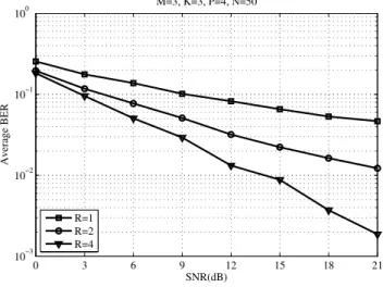
M=3, K=3, P=4, N=50
R=1 R=2 R=4
Fig. 2. BER vs. SNR performance.
0 5 10 15 20 25
10−5 10−4 10−3 10−2 10−1 100
SNR(dB)
NMSE
M=3, K=3, P=4, N=50
R=1 R=2 R=4
Fig. 3. NMSE ofAb.
angles of arrival, and additive noise. Our goal is to evaluate the impact of the number R of relays on the performance of the proposed PARAFAC receiver using the ALS algorithm described in the previous section.
Figure 2 shows the average bit-error-rate (BER) versus the signal-to-noise-ratio (SNR) at the base station for different number of relays. It can be seen that the BER performance is considerably improved as the number of relays increases. We can also conclude from the slope of the BER curves that a higher diversity order is obtained as more relays are used to assist the communication of the users with the base station.
In Figure 3, we evaluate the accuracy of the estimation of the array response matrix A provided by the proposed
PARAFAC receiver. For this sake, we compute the following normalized mean square error (NMSE) measure from L = 1000 Monte Carlo runs: NMSE(Ab) =
1
L L
P
l=1
vec(Ab(l)−A)Hvec(Ab(l)
−A)
vec(A)Hvec(A) . Note that more satisfactory
results are obtained with a higher number of relays, as expected. In particular, using R = 4 relays leads to a considerably improved estimation accuracy in comparison with the configurations withR= 1and 2 relays.
VI. CONCLUSION ANDPERSPECTIVES
We have addressed the problem of blind multiuser detection and channel estimation for uplink cooperative relay-assisted DS-CDMA systems. Relying on a trilinear PARAFAC modeling for the composite received data tensor (SD and RD links combined), our receiver exploits space (first dimension), cooperative/spreading (second dimension) and time (third dimension) diversities for blindly estimating the users’ transmitted symbols and channels and it is designed to operate in the case where all the relays transmit simultaneously towards the base station. This work has several perspectives, and among them we can cite:
• A comparison with traditional pilot-assisted receivers
using ZF and/or MMSE detection;
• The impact of other relay processing methods such as
decode-and-forward (DF) and selective DF;
• The modeling of multiuser interference on the SR links;
• The use of multiple antennas and direct-sequence
spreading at the users’ transmission;
• The design of distributed tensorial space-time codes
across the multiple relays.
REFERENCES
[1] J. N. Laneman, D. N. C. Tse, and G. W. Wornell, “Cooperative diversity in wireless networks: efficient protocols and outage behavior,” IEEE Trans. Inf. Theory, vol. 50, no. 12, pp. 3062–3080, Dec. 2004. [2] K. J. Ray Liu, A. K. Sadek, W. Su, and A. Kwasinski, “Cooperative
communications and networking, Cambridge University Press, 2009.” [3] F. Roemer and M. Haardt, “Tensor-based channel estimation and
iterative refinements for two-way relaying with multiple antennas and spatial reuse,” IEEE Trans. Signal Process., vol. 58, no. 11, pp. 5720–5735, Nov. 2010.
[4] A. Y. Kibangou and A. L F. de Almeida, “Distributed PARAFAC based DS-CDMA blind receiver for wireless sensor networks,” Proc. SPAWC 2010, Marrakech, Morocco, Jun. 2010.
[5] A. Y. Kibangou and A. L F. de Almeida, “Distributed Khatri-Rao space-time coding and decoding for cooperative networks,” Proc. EUSIPCO 2011, Barcelona, Spain, Aug. 2011.
[6] R. A. Harshman,Foundations of the PARAFAC procedure: Models and conditions for an “explanatory” multimodal factor analysis, UCLA Working Papers in Phonetics, 16th edition, Dec. 1970.
[7] J. D. Carroll and J.-J. Chang, “Analysis of individual differences in multidimensional scaling via an N-way generalization of “Eckart-Young” decomposition,” Psychometrika, vol. 35, no. 3, pp. 283–319, Sep. 1970.
[8] C. A. R Fernandes, A. L. F. de Almeida, and D. B. da Costa, “ Unified tensor modeling for blind receivers in multiuser uplink cooperative systems,” IEEE Signal Process. Lett., vol. 19, no. 5, pp. 247-250, May 2012.
[9] N. D. Sidiropoulos, G. B. Giannakis, and R. Bro, “Blind PARAFAC receivers for DS-CDMA systems,” IEEE Trans. Signal Process., vol. 48, no. 3, pp. 810–823, Mar. 2000.
[10] N. D. Sidiropoulos, R. Bro, “On the uniqueness of multilinear decomposition ofN-way arrays,” Journal of Chemometrics, vol. 14, pp. 229–239, 2000.
[11] J. Kruskal, “Three way arrays: Rank and uniqueness of trilinear decomposition with applications to arithmetic complexity and statistics,”
Linear Algebra and its Applications, vol. 18, pp. 95–138, 1977. [12] X. Liu, and N. D. Sidiropoulos, “PARAFAC methods for blind
beamforming: multilinear ALS performance and CRB” Proc. ICASSP 2000, Istanbul, Turkey, June 2000.
[13] R. B. Ertel, P. Cardieri, K. W. Sowerby, T. S. Rappaport, and J. H. Reed, “Overview of spatial channel models for antenna array communication systems.,”IEEE Personal Commun., vol. 5, no. 1, pp. 10–22, Feb. 1998. [14] A.-J. van der Veen, “Algebraic methods for deterministic blind beamforming.,” Proc. of IEEE, vol. 86, no. 10, pp. 1987–2008, Oct. 1998.