UNIVERSIDADE DE LISBOA
Faculdade de Ciências
Departamento de Informática
EXTENDED PERSPECTIVE SYSTEM
VISUALIZER
VERSÃO PÚBLICA
Robin Charles Rosa Burgess
DISSERTAÇÃO
MESTRADO EM ENGENHARIA INFORMÁTICA
Interacção e Conhecimento
UNIVERSIDADE DE LISBOA
Faculdade de Ciências
Departamento de Informática
EXTENDED PERSPECTIVE SYSTEM
VISUALIZER
Robin Charles Rosa Burgess
DISSERTAÇÃO
MESTRADO EM ENGENHARIA INFORMÁTICA
Interacção e Conhecimento
Trabalho orientado pelo Prof. Doutora Teresa Chambel e co-orientado por Prof. Doutora Ana Paula Cláudio
Acknowledgements
I would like to thank my supervisors Prof. Teresa Chambel and Prof. Ana Paula Cláudio for their help, work and patience. I would also like to extend my gratitude to all the other members of the NAADIR team: Prof. Luís Romão, Prof. Carlos Albuquerque, Prof. Beatriz Carmo, Prof. Vítor Correia, Prof. Manuel Couceiro, Prof. Susana Rosado-Ganhão, Prof. Ana Guerreiro, Christian Marques, Sara Garcia, Diogo Henriques and Vera Osório.
I would like to thank the FCT (Fundação para a Ciência e Tecnologia) and acknowledge their investment in the research and development project NAADIR (PTDC/AUR-AQI/098388/2008) and my scholarship. My thanks also go to the LabMAg and LaSIGE laboratories of the Faculty of Science of the University of Lisbon for providing a pleasant and friendly workspace.
My appreciation goes to the participants in the studies described in this dissertation for their collaboration.
vii
Resumo
A projecção perspectiva linear tem sido o modo predominante de desenhar imagens de espaços tridimensionais há séculos, sejam estes desenhos manuais ou computacionais. Em particular, os arquitectos usam o sistema perspéctico linear no desenho formal como forma de representar o seu trabalho como este seria observado através da visão humana. Porém, este sistema perspéctico é limitado nesta capacidade. Quando se utilizam ângulos de visão mais alargados, os desenhos que utilizam projecção perspectiva linear manifestam uma distorção que dificulta a interpretação da imagem e limitam a capacidade desta perspectiva de verdadeiramente representar a visão humana. Aos 180º de ângulo de visão, o máximo possível neste sistema, a imagem passa a ser inteiramente irreconhecível.
Formas de projecção perspectiva não lineares, ou curvilíneas, como a perspectiva cilíndrica ou panorâmica ou a perspectiva esférica, não apresentam a mesma limitação. Usando estas perspectivas, o ângulo de visão pode ser alargado até aos 360º sem que esta distorção apareça. Porém, estes sistemas também não são soluções perfeitas já que a rectilinearidade não é preservada.
O Sistema Perspéctico Expandido (EPS) foi criado por membros da equipa NAADIR (New Approach on Architectural Drawings Integrating computeR
descriptions) para responder às limitações dos sistemas individuais existentes. O seu
trabalho, bem como esta dissertação, foram realizados no âmbito do projecto NAADIR (PTDC/AUR-AQI/098388/2008), financiado pela Fundação para a Ciência e Tecnologia. A equipa inclui membros da Faculdade de Ciências e da Faculdade de Arquitectura da Universidade de Lisboa.
Este sistema une os sistemas perspécticos linear, esférico e cilíndrico num contínuo híbrido controlado por dois parâmetros. Variando estes dois parâmetros, o utilizador pode encontrar sistemas intermédios e obter deste modo uma melhor visualização do espaço tridimensional representado. O sistema tem também o objectivo
viii
de ajudar os arquitectos no seu processo de design, ajudando-os a ter uma melhor visualização do espaço em que trabalham.
O sistema EPS realiza a projecção em dois passos e utiliza duas superfícies, uma superfície de projecção elipsoidal e uma superfície de representação plana. O primeiro passo consiste em projectar o espaço 3D sobre a superfície de projecção. O segundo consiste em mapear a superfície de projecção sobre a superfície de representação, de modo análogo à cartografia, em que a superfície da terra é mapeada sobre um plano, criando um mapa. A imagem criada sobre a superfície de representação é a imagem final. O elipsóide da superfície de projecção pode ser manipulado com dois parâmetros: raio e excentricidade. Esta manipulação afecta a perspectiva final. Um raio e excentricidade pequenos produzem uma perspectiva mais próxima da esférica, um raio pequeno e excentricidade elevada aproximam uma perspectiva cilíndrica, e um raio elevado aproxima a perspectiva linear. É possível também escolher um de três modos diferentes de mapeamento da superfície de projecção sobre a de representação, o modo esférico (projecção azimutal equidistante), o modo cilíndrico (projecção sinusoidal) e o modo híbrido.
Devido à sua natureza dinâmica, o EPS é sobretudo útil implementado computacionalmente, com uma interface que permita a sua fácil manipulação. Em trabalho prévio, a equipa NAADIR iniciou a implementação do EPS Visualizer, um visualizador de modelos 3D que implementa o sistema EPS. Nesta fase, o visualizador foi desenvolvido ainda sem implementar a maior parte do sistema EPS e sem ser avaliado.
Nesta versão inicial estava apenas implementada a projecção usando o mapeamento esférico até aos 180º de ângulo de visão. A interface do visualizador era composta por quatro viewports, um principal e três secundários, e por dois menus. Cada
viewport permitia visualizar o espaço 3D a partir de cima, baixo, frente, trás, esquerda
ou direita, usando projecção perspectiva linear ou projecção paralela, ou permitia visualizar o espaço a partir de uma câmara usando projecção perspectiva linear ou usando o sistema EPS. Os menus permitiam manipular a posição e orientação da câmara, o ângulo de visão, a rotação da câmara em relação ao seu eixo frente-trás e os parâmetros do sistema EPS, raio e excentricidade. O visualizador podia ainda renderizar os modelos em wireframe ou com faces opacas. A renderização em wireframe era
ix
relativamente rápida mas a renderização com faces sólidas era lenta, demorando cerca de um minuto a produzir uma única imagem.
O projecto descrito por esta dissertação teve dois objectivos principais. O primeiro foi a conclusão do EPS Visualizer. Sub-objectivos desta tarefa foram a implementação do sistema EPS por inteiro, o melhoramento do seu desempenho e o melhoramento da sua interface com o utilizador. O segundo foi a realização de duas avaliações do visualizador. As avaliações tiveram como objectivo avaliar a qualidade da interface, ajudar a identificar formas de melhorar a interface e avaliar a utilidade do sistema EPS como ferramenta no processo de design de arquitectos.
Durante o desenvolvimento do projecto, o EPS Visualizer foi concluído e foram realizadas as avaliações previstas, atingindo-se os objectivos.
O desenvolvimento do visualizador pode ser dividido em quatro áreas. A implementação do sistema EPS, o melhoramento do desempenho, a restruturação interna do software e o melhoramento da interface.
Foram implementadas as projecções usando o mapeamento esférico até aos 360º, usando o mapeamento cilíndrico e usando o mapeamento híbrido. Completou-se assim a
implementação do sistema EPS no visualizador.
O desempenho do software foi melhorado implementando-se multi-threading para o cálculo da projecção. Isto permitiu separar a interface do processo de rendering do cálculo da projecção EPS e permitiu também que o cálculo da projecção fosse dividido pelos múltiplos cores que são hoje habituais em processadores. Foi também criado um novo sistema de rendering de faces opacas com desempenho similar ao desempenho da renderização de wireframe. Para permitir a implementação do
multi-threading, foi necessário reestruturar o visualizador. Este processo resultou num
número maior de classes mais pequenas e num programa que mais facilmente poderia ser adaptado ao multiprocessamento.
Finalmente, a interface foi alterada e melhorada. Este processo teve duas fases. A primeira fase ocorreu antes da primeira avaliação. Os menus for reorganizados, o controlo da câmara com o rato foi melhorado e fizeram-se outras modificações menores. Após a avaliação deu-se a segunda fase do desenvolvimento da interface. Foram implementadas funcionalidades sugeridas por observações e sugestões feitas durante a avaliação. Surgiram opções alternativas para certos elementos da interface que foram
x
implementadas em versões alternativas da interface. Estas versões alternativas foram depois testadas na segunda avaliação de modo a se escolher os elementos melhores das duas versões.
A primeira avaliação foi realizada no contexto de um workshop e teve como foco principal o estudo da utilidade do sistema EPS como suporte ao design arquitectónico. Alunos de arquitectura tiveram acesso ao EPS Visualizer durante o workshop no contexto de um projecto de design de arquitectura. Cada aluno pôde usar a ferramenta livremente tendo no final preenchido um questionário sobre a sua experiência. Os alunos mostraram interesse em usar a ferramenta no futuro e de a ver implementada em software de modelação tridimensional. Consideraram a interface fácil de usar.
A segunda avaliação teve como foco o estudo da usabilidade do visualizador e consistiu em entrevistas individuais supervisionadas com guião. Os utilizadores foram divididos em três grupos: alunos de arquitectura, profissionais de arquitectura e alunos de informática com experiência de computação gráfica e modelação 3D. Os utilizadores foram conduzidos através de um conjunto de tarefas em que avaliaram cada elemento da interface. Para cada elemento das duas versões do visualizador, os utilizadores puderam experimentar ambas as versões e indicar a sua preferência. No final preencheram um questionário sobre a sua opinião global acerca do visualizador, incluindo um teste SUS (System Usability Scale). Os utilizadores avaliaram a interface de forma positiva, indicando as suas preferências sobre versões alternativas de elementos da interface.
O Visualizador EPS foi concluido com sucesso, tendo sido implementado o sistema EPS por completo e o desempenho e interface da aplicação melhorados. Realizaram-se ambas as avaliações com bons resultados. Foram portanto atingidos os objectivos propostos. Foram ainda publicados três artigos científicos no contexto desta tese.
Palavras-chave: projecção perspectiva curvilínea, computação gráfica, design
arquitectónico, sistema de perspectiva expandido, renderização, multi-threading, interfaces com utilizadores
xi
Abstract
For centuries, linear perspective projection has been the dominant way of accurately drawing the world as seen from the human eye. In particular, it has been a tool used by architects in rigorous formal drawing. However, this system is limited by the distortions that manifest when large fields of view are used, making the interpretation of the image more difficult and limiting its ability to express human vision in its full dynamic breadth. Alternative curvilinear perspective systems do not share this limitation and can serve as a complement to linear perspective projection, though they are not without their own limitations. The Extended Perspective System is an alternative system that blends linear and curvilinear perspective systems into a single continuum, responding to the limitations of the individual systems. In this capacity, it also aims to aid architects in their design process.
In previous work, a computational implementation of the EPS system, the EPS Visualizer was started to demonstrate its properties and test its usefulness as a tool for architects. However, it was left incomplete, lacking most key perspective features and leaving the EPS' usefulness unevaluated.
The project described in this dissertation had two main objectives. The first was to complete the EPS Visualizer, implementing the EPS system fully, improving its performance and user interface. The second was to perform two evaluations, the first to determine the usefulness of the EPS system as a tool in the architectural design process and the second to evaluate the usability of the visualizer's user interface.
The EPS Visualizer was completed and the two evaluations were performed, fulfilling the objectives of the project. The evaluation of the usefulness of the EPS system indicated that there was interest on the part of architects and architecture students in the visualizer and a desire to see it integrated into design software. The evaluation of the user interface aided in its development and gave positive results overall.
Keywords: curvilinear perspective, computer graphics, architectural design, extended
xiii
Contents
Resumo ... vii
Abstract ...xi
Contents ... xiii
List of Figures ... xvii
1 Introduction ... 1
1.1 Motivation... 1
1.2 Objectives ... 3
1.3 Context ... 4
1.4 Work Plan ... 4
1.5 Developed Work and Contributions ... 5
1.6 Document Structure ... 6
2 State of the Art ... 9
2.1 The Concept of Projection ... 9
2.1.1 Linear Perspective Projection ... 10
2.1.2 Curvilinear Perspective Projection ... 11
2.2 The EPS Concept ... 12
2.2.1 Fundamental Concepts ... 13 2.2.2 Mutability ... 14 2.2.3 Mapping ... 16 2.3 Related Work ... 19 2.3.1 Raytracing Techniques... 19 2.3.2 Multi-Camera Techniques ... 20
2.3.3 Non-Raytracing Single Camera Techniques ... 22
2.4 Previous Work ... 24
2.4.1 The Viewports ... 25
2.4.2 The Camera and Cursor ... 25
xiv
2.4.4 Rendering ... 26
2.4.5 File Interface ... 28
2.4.6 Implementation and Class Structure ... 28
2.5 Summary ... 29
3 EPS Visualizer ... 31
3.1 Requirements ... 31
3.2 EPS Visualizer Core ... 32
3.2.1 EPS Projection Modes ... 32
3.2.2 Solid Faces Rendering ... 33
3.2.3 Multi-Threading ... 34 3.2.4 Code Restructuring ... 38 3.3 User Interface... 40 3.3.1 Restructuring Phase ... 40 3.3.2 Refinement Phase... 44 3.3.3 Final Version ... 48 3.4 Summary ... 48 4 User Evaluation ... 49
4.1 The EPS for Architectural Design ... 49
4.1.1 Method ... 49 4.1.2 Participants ... 51 4.1.3 Results ... 51 4.1.4 Discussion ... 53 4.2 EPS Usability ... 53 4.2.1 Method ... 54 4.2.2 Participants ... 56 4.2.3 Results ... 56 4.2.4 Discussion ... 61 4.3 Summary ... 61
xv
5 Conclusion and Future Work ... 63
5.1 Overview and Conclusions ... 63
5.2 Future Work ... 64
References ... 67
Appendices ... 71
Appendix A –First Evaluation ... 73
A1 –Questionnaire ... 75
A2 – Quick Start Guide ... 81
A3 –Results ... 85
A4 – Photos ... 89
Appendix B –Second Evaluation ... 95
B1 –Interview Scripts ... 97 B2 –User’s Drawings ... 119 B3 –Interviewer’s Drawings ... 123 B4 –User’s Manual ... 127 B5 –Results ... 131 B6 – Photos ... 139
Appendix C –Class Diagrams ... 143
C1 –Initial Version ... 145
C2 –Final Version ... 149
xvii
List of Figures
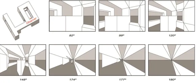
Figure 1: The effect of widening the field of view in linear perspective projection. Figure 2: An example of linear perspective projection.
Figure 3: Three point perspective projection. Figure 4: A photograph taken with a fish-eye lens. Figure 5: A drawing using cylindrical perspective.
Figure 6: A view of the three perspective systems that the EPS brings together. Figure 7: An illustration of the radius parameter.
Figure 8: An illustration of the eccentricity parameter.
Figure 9: The effects of the radius and eccentricity parameters demonstrated. Figure 10: The three projection modes.
Figure 11: Flocon and Barre’s illustration of the azimuthal projection of a half sphere. Figure 12: An example of Glassner (2000)’s cubist cameras.
Figure 13: An example of artistic projection using Yu and McMillan’s framework. Figure 14: An example of an MCOP image.
Figure 15: An multiprojection still life containing 10 camera groups made using Agrawala et al.’s system.
Figure 16: Sticky camera scene from animation “Ryan”.
Figure 17: A cylindrical projection rendering using Trapp and Döllner’s approach. Figure 18: A projection using nonlinear projectors created with Brosz et al.’s interface. Figure 19: Interface of the initial version of the EPS Visualizer.
Figure 20: The cursor.
Figure 21: The cube map concept illustrated.
Figure 22: Illustration of the process of mapping the images to grids in 3D space. Figure 23: Simplified UML class diagram.
Figure 24: A 3D model rendered with the new algorithm. Figure 25: UML Activity Diagram of thread activity.
xviii
Figure 26: A simplified UML diagram of class relationships of the present version of the EPS Visualizer.
Figure 27: The new EPS Visualizer interface.
Figure 28: Showing the two colour schemes side by side, the initial version and the new version.
Figure 29: The position and projection control windows in EPS Visualizer. Figure 30: The final interface.
Figure 31: The two camera cursor colour schemes. Figure 32: The three methods of changing the viewports. Figure 33: Photo of the workshop.
Figure 34: Graphs of the answers for questions 5, 6 and 10. Figure 35: A view of the interviews taking place.
Figure 36: Graph of the answers comparing the visualizer to similar software and free-hand drawing.
1
Chapter 1
Introduction
This chapter introduces the work described in this dissertation, describing its motivation, objectives and context, as well as its planning, the developed work and contributions.
1.1 Motivation
For centuries, hand drawings have been the fundamental tool of the architect’s craft. Informal drawing is an aid in the process of conception and design. Formal architectural drawing, using strict graphical projection, allows the rigorous representation of the work. Parallel projection, which maintains the relative lengths and orientations of lines, is used to express the shape of objects in a way that conveys the information required to construct the object. Classical linear perspective projection is used to represent the object as seen by the naked human eye, providing the viewer with a better idea of what the object will look like when constructed.
Despite its precision and historical success, classical perspective projection is in no way a perfect method of simulating human perception. For classical perspective projection to produce results that are pleasing to the human eye, the field of view must be relatively narrow. As shown in Figure 1, when the field of view is widened, classical perspective projection begins to distort the object depicted, the centre of vision becoming more and more distant and the periphery more and more prominent. When the full 180º field of view is used, the image becomes entirely distorted and unrecognizable; all points in view having shifted into a single point.
Though other forms of projection have appeared, such as the curvilinear methods described in section 2.1.3, they have never managed to replace classical linear perspective projection. Firstly, they too are not perfect methods of depicting reality.
2
Human vision is a complex and dynamic cognitive process and could never be perfectly mirrored by a static image. Secondly, they are usually far more difficult to use than linear perspective projection. This being said, when put together and used to complement each other, they can offer the viewer a much wider breadth of information than any single system ever could.
Figure 1: The effect of widening the field of view in linear perspective projection. One reason why rough sketching is still so useful to architects is its flexibility and ability to disregard the strict restrictions of formal projection systems. It can be distorted whichever way is most useful. Indeed, it is not uncommon for curvature to spontaneously appear in free-hand drawing. In formal depictions, it is too complex to use curvilinear perspective projection due to lines becoming curved depending on their orientation (Flocon and Barre, 1968). Determining the exact curvature of these lines and then drawing them is simply too complex a task to be done by humans in useful time. This is not a problem in informal hand-drawing where the process can be done intuitively.
The Extended Perspective System (EPS), designed by members of the NAADIR team, brings together linear and curvilinear systems (cylindrical and spherical systems) in to a continuous framework, creating a vast array of intermediate projection systems. It is the aim of the NAADIR team to develop and implement the EPS system so as to bring the flexibility of free-hand drawing to the realm of formal depictions and making the advantages of each individual system, as well as an intermediate continuum of new systems, easily available to the user. This thesis plays an important part in achieving
3
that goal by implementing the EPS system computationally with an easy-to-use interface
1.2 Objectives
The primary objective of the thesis was to complete the EPS Visualizer, an interactive implementation of the EPS system started previously by the NAADIR team. This is composed of two different interweaved tasks:
1. Complete the implementation of the EPS Visualizer. This consists of expanding the software’s projection capacity by implementing the EPS system fully, optimizing these capacities in order to improve performance, and adjusting its interface according to the results of the evaluation process described below.
2. Evaluate the EPS Visualizer both as a tool to support the architectural design process and as a user interface, in regards to its functionalities and usability as an interactive tool. This was performed in two different evaluation moments. The first one was an evaluation of the EPS system’s usefulness in the architectural design process and took place in a workshop at the Faculty of Architecture, where students were able to use the application in the context of their university projects. The second one was a usability user evaluation with architecture students, architecture professionals and computer engineers with experience with computer graphics.
The development of the software was driven by three fundamental requirements.
Expand the projection capabilities of the Visualizer by completing its implementation of the EPS system. Specifically, implement the spherical projection mode for the full 360º field of view, implement the cylindrical projection mode and implement the hybrid projection mode.
Improve the performance of the Visualizer so as to approximate real-time as much as possible.
Improve the usability Interface of the Visualizer
The first requirement was completed before the others, as the associated algorithms had already been implemented by other members of the team in Octave when the project started. The second requirement took a significantly longer amount of time, due to its complexity. It proved necessary to restructure the application, apply multi-threading and design a new solid face rendering algorithm. The greatest amount of time
4
was given to the final requirement as it went through several stages and it depended greatly on the two evaluations. The interface was restructured and then refined, in accordance to both expert knowledge and the user evaluations.
1.3 Context
The work presented in this dissertation was developed within the context of the NAADIR project (PTDC/AUR-AQI/098388/2008), funded by the FCT, in collaboration with a team of researchers and students in the fields of Architecture, Drawing, Geometry, Mathematics, Human-Computer Interaction and Computer Graphics from the Faculty of Architecture and the Faculty of Science of the University of Lisbon. The author joined the team to continue the work of Christian Marques, who had previously developed work for the team in the context of his own Master’s in Informatics Engineering. The work was done in the Laboratory of Agent Modelling (LabMAg) and the Large-Scale Informatics Systems Laboratory (LaSIGE) of the Department of Informatics of the Faculty of Science of the University of Lisbon.
1.4 Work Plan
The work for the thesis was done between mid-September 2012 and the end of June 2013. The work plan went as follows:
15th – 30th September
Reading the prior work and documentation
1st October – 5th December
Initial development in preparation for the workshop and the first evaluation moment
6th – 11th December
The first evaluation moment – EPS support for design in Architecture
12th December – 1st February
Analysis of the workshop data and writing of the preliminary report
1st February – 1st May
5
2nd – 22nd May
The second evaluation moment – EPS usability
22nd May – 30th June
Analysis of the evaluation results and finalization of the Visualizer
1st July – 31st July
Writing of the dissertation
During the project there were some changes to the scheduling. For logistic reasons, the first evaluation moment’s schedule was changed from November to mid-December, which delayed the preliminary report. In addition to this, during the second half of the project three papers were written and a trip to Shanghai took place in early July to present one of those papers in the international conference CAAD Futures 2013. Although introducing a delay in certain phases, it greatly enriched the contributions of the thesis and the project. Despite these changes, the work was completed within the allotted timeframe. For personal reasons, the writing of the dissertation was placed on hiatus in August 2013 and resumed in late 2013/2014.
1.5 Developed Work and Contributions
During the project, the following tasks were completed:
The software’s projection capabilities were completed according to the EPS specification.
Multi-Threading was added to the software, so as to smoothen the interface performance.
A new faster way of rendering the models solidly with hidden surface removal was applied.
The interface was given an overhaul, improving it.
Two evaluations of the software took place regarding the usefulness of the EPS system in the architectural design process and of the usability of the software. The work was structured incrementally, taking the previous version and adding the required features and modifications step-by-step as opposed to in parallel or monolithic chunks so as to allow testing at each step, maintaining the correctness of the software throughout and avoiding obscured bugs as much as possible. On the other hand, the
6
development of the user interface was iterative, each iteration alternating with the evaluation moments.
The thesis led to several contributions to the field in the form of conference papers:
Correia, V., Romão, L., Ganhão, S., Couceiro da Costa, M., Guerreiro, A., Henriques, D., Garcia, S., Albuquerque, C., Carmo, M. B., Cláudio, A. P., Chambel, T., Burgess, R., Marques, C., "A New Extended
Perspective System for Architectural Drawings". In Proc. of 15th CAAD
Futures' 2013, 15th Int. Conf. on Computer Aided Architectural Design, Tongji University, Shanghai, China, July 3-5, 2013. In Jianlong Zhang, and Chengyu Sun (eds.), Global Design and Local Materialization: Communications in Computer and Information Science, vol.369, pp.63-75, 2013.
Burgess, R., Cláudio, A. P., Chambel, T., Carmo, M. B., Albuquerque, C., Marques C., Correia, V., Romão, L., Ganhão, S., Couceiro da Costa, M., Guerreiro, A., Garcia, S., Henriques, D., "Visualizador Interactivo de
Desenhos Arquitectónicos em Sistema de Perspectiva Expandido". Proc.
Interação'2013, 5º Conferência Nacional de Interação Pessoa-Máquina, pp.144-151, Vila Real, Portugal, Nov 7-8, 2013.
Burgess, R., Chambel, T., Cláudio, A. P., Carmo, M. B., Albuquerque, C., Correia, V., Romão, L., Ganhão, S., Couceiro da Costa, M.,
Guerreiro, A., Garcia, S., "Interactive Visualizer for the Extended
Perspective System as Support for Architectural Design". In Proc. of
GRAPP'2014, 9th International Conference on Computer Graphics Theory and Applications, pp.453-463, Lisbon, Portugal, January 5-8, 2014.
The CAAD Futures 2013 and GRAPP 2014 papers were presented at the respective conferences by the author of this dissertation, who also participated in the latter conference as a student volunteer.
1.6 Document Structure
The rest of this dissertation is divided into four more chapters.
Chapter 2 describes the state of the art. It first briefly describes the existing perspective systems, along with the EPS concept the project is based on. It then describes previous work done implementing curvilinear perspective computationally as well as the previous work done on the EPS Visualizer, which this project aimed to complete.
7
Chapter 3 describes the development of the EPS Visualizer. The first section of the chapter describes the work done to the software’s algorithmic capabilities and its optimization, the second section describes the work done to the software’s interface.
Chapter 4 describes the two user evaluations done of the usefulness of the EPS system for the architectural design process and of the usability of the EPS Visualizer, including their methodology, a description of the results and conclusions taken.
Finally, chapter 5 concludes the dissertation giving an overview and conclusion of the project and hints for future work that might be done, beyond the scope of this thesis, should the project be continued.
Because this is the public version of the thesis, chapters 2, 3, 4 and the appendices have been omitted.
63
Chapter 5
Conclusion and Future Work
5.1 Overview and Conclusions
The work consisted of two primary objectives; the development of the EPS Visualizer and its evaluation as a tool to aid architects in their design process. Both of these tasks were completed.
As a reminder, the functional requirements for the project were the following:
Implementing the full spherical mapping mode for 360º field of view.
Implementing the cylindrical mapping mode.
Implementing the hybrid projection modes.
The non-functional requirements were:
Improving the usability of the user interface
Improving the performance of the software.
All functional requirements were completed. The Visualizer implements the full Extended Perspective System, providing the user with the ability to flexibly parameterize the perspectives in which their architectural models are projected. More specifically, it allows them to interactively control the radius and eccentricity of an ellipsoidal projection surface, resulting in a visualization of a 3D scene using linear, spherical and cylindrical perspective projections as well as a wealth of intermediate projections. Concurrently, they can navigate the 3D scene, by controlling the camera and the viewport.
To improve the software’s performance, it was restructured to use multi-threading and a new solid face rendering algorithm was created. Real-time efficiency was not achieved except for simpler models and it is difficult to notice a great change in the efficiency of wireframe rendering. However, due to the nature of multi-threading the
64
difference is likely to become more noticeable as the number of cores in processors doubles according to Moore’s Law (Moore, 1965). The change also improved the software’s usability by eliminating the situations where the application froze while calculating the projection of heavier 3D models.
Furthermore, the performance of solid face rendering improved drastically. While the original rendering algorithm required almost a minute to create a single image, the new algorithm is practically as fast as wireframe rendering, an improvement of a whole order of magnitude. This change in performance came with a decrease in the quality of the image rendered, where in certain situations faces can bleed through each other unexpectedly.
The user interface was restructured and refined, taking into account the results of two user evaluations carried out during the work.
The two evaluations were carried out with the intent of evaluating the usefulness of the EPS concept as a tool for architects and evaluating the usability of the EPS Visualizer interface for those in the field of architecture as well as those outside the field with some experience with 3D graphics.
The first evaluation showed that students of architecture see the tool as potentially useful in their design process, that they would like to see it integrated into modelling software and that it produces images of interest to their work. They found the interface flexible and relatively easy to use. The second evaluation indicated that users liked the layout, features, produced images and flexibility of the interface, but hinted that the EPS system itself may take some practice to use effectively. The results of the two evaluations were overall quite positive, and provided insights on how the tool could be improved. These insights led to further alterations of the user interface and the addition of new features such as the settings options, the ability to embed the projection floating window into the main window and the orbital control.
5.2 Future Work
Despite the fact that the objectives set out for the tool’s development were mostly complete, there is still space for improvement and its algorithms can be further optimized. For example, it is theoretically possible to replace the numerical calculations of partial elliptical circumferences with a polynomial approximation of the partial
65
elliptic integral of the second kind, though it is unknown how much this would effectively improve performance as a working one was not found in the literature explored. The solid face rendering algorithm too can still be improved, hopefully eliminating the faults of the new rendering method. It is possible that having both the old and the new methods side by side could be useful in different situations. The slower method could be used to produce high quality images to be used punctually, while the fast method could be used to explore perspectives quickly and effectively in the same way as wireframe rendering.
Other paths that can be taken to improve the software include: improving camera control features; integration with existing 3D modelling software, this way the EPS depictions could be used together with editing and throughout all the design process; development of the EPS system itself, adding new parameters and projection surfaces and thus increasing the variety of projections available to the user; and expansion beyond the domain of architectural design into other realms such as product design, videogames, education, art and culture, through new ways to communicate and depict the world.
67
Bibliography
Agrawala, M., Zorin, D., Munzner, T., 2000. Artistic multiprojection rendering. In
Proceedings. of the Eurographics Workshop on Rendering Techniques, pp. 125-136,
London, UK. Springer-Verlag.
Bonbon, B.S., 1985. La Geometrie Spherique Tridimensionnelle. Éditions Eyrolles, Paris.
Brooke, J., 1996. "SUS: a "quick and dirty" usability scale". In P. W. Jordan, B. Thomas, B. A. Weerdmeester, & A. L. McClelland. Usability Evaluation in Industry. London: Taylor and Francis.
Brosz, J., Samavati, F. F., Carpendale, S. M. T., Sousa, M. C. 2007. Single camera
flexible projection. In Proceedings of the 5th International Symposium on
Non-Photorealistic Animation and Rendering (NPAR’07), pages 33–42. ACM.
Burgess, R., Chambel, T., Cláudio, A. P., Carmo, M. B., Albuquerque, C., Correia, V., Romão, L., Ganhão, S., Couceiro da Costa, M., Guerreiro, A., Garcia, S., Interactive
Visualizer for the Extended Perspective System as Support for Architectural Design.
In Proc. of GRAPP'2014, 9th International Conference on Computer Graphics Theory and Applications, pp.453-463, Lisbon, Portugal, January 5-8, 2014.
Burgess, R., Cláudio, A. P., Chambel, T., Carmo, M. B., Albuquerque, C., Marques C., Correia, V., Romão, L., Ganhão, S., Couceiro da Costa, M., Guerreiro, A., Garcia, S., Henriques, D., Visualizador Interactivo de Desenhos Arquitectónicos em Sistema de
Perspectiva Expandido. Proc. Interação'2013, 5º Conferência Nacional de Interação
Pessoa-Máquina, pp.144-151, Vila Real, Portugal, Nov 7-8, 2013.
Carlbom, I., Paciorek, J., 1978. Planar Geometric Projections and Viewing Transformations. ACM Comput. Surv. 10, 4 (December 1978), 465-502.
Casas, F. R., 1983. Flat-Sphere Perspective, Leonardo, Vol.16, No. 1 (Winter) pp. 1-9, The MIT Press.
Christian, M., Extended Perspective System Visualizer, Faculdade de Ciências da Universidade de Lisboa, 2011.
68
Coleman, P., Singh, K. R., 2004. Rendering your animation nonlinearly projected. In
Proceedings of the 3rd international symposium on Non-photorealistic animation and rendering, NPAR ’04, pp. 129–156, New York, NY, USA, ACM.
Correia V., Romão, L.,: Extended perspective System. In Proceedings of the 25th eCAADe International Conference, pages 185-192, (2007).
Correia V., Romão L., Rosado-Ganhão, S., Albuquerque, C., Cláudio, A. P., Carmo, M. B., “A new perspective on Perspective”. Poster at Nexus 2010 Conference, Porto, June 2010.
Correia, V., Romão, L., Ganhão, S., Couceiro da Costa, M., Guerreiro, A., Henriques, D., Garcia, S., Albuquerque, C., Carmo, M. B., Cláudio, A. P., Chambel, T., Burgess, R., Marques, C., "A New Extended Perspective System for Architectural Drawings". In Proc. of 15th CAAD Futures' 2013, 15th Int. Conf. on Computer Aided Architectural Design, Tongji University, Shanghai, China, July 3-5, 2013. In Jianlong Zhang, and Chengyu Sun (eds.), Global Design and Local Materialization: Communications in Computer and Information Science, vol.369, pp.63-75, 2013. Craig, T., A Treatise on Projections, U.S. Coast and Geodetic Survey, Washington:
Govt. Print. Off., 1882
Flocon, A., Barre, A., 1968. La Perspective Curviligne, Flammarion Éditeur, Paris. Glassner, A. S., 2000. Cubism and cameras: Free-form optics for computer graphics.
Technical Report MSR-TR-2000-05, Microsoft, California.
Gröller, E., 1995. Nonlinear ray tracing: Visualizing strange worlds. Visual Computer, 11(5):263-274, May.
Hansen, R., 1973. This Curving World: Hyperbolic Linear Perspective, The Journal of
Aesthetics and Art Criticism, Vol. 32, No. 2 (Winter) pp. 147-161, Wiley.
Lund, A.M., 2001. Measuring Usability with the USE Questionnaire. STC Usability SIG
Newsletter, 8:2.
Moore, G. E., 1965. Cramming more components onto integrated circuits. Electronics Magazine. p. 4.
Moose, M., 1986. Guidelines for Constructing a Fisheye Perspective, Leonardo, Vol. 19, No. 1, pp. 61-64, The MIT Press.
Rademacher, P., Bishop, G., 1998. Multiple-center-of-projection images. In
Proceedings of the 25th annual conference on Computer graphics and interactive techniques, SIGGRAPH ’98, pages 199–206, New York, NY, USA, ACM.
69
Salomon, D., 2006. Transformations and Projections in Computer Graphics, Springer Verlag, August 2006.
Singh, K., 2002. A fresh perspective. Graphics Interface (GI'02), pp. 17-24, May (2002).
Trapp, M., Döllner, J., 2008. A generalization approach for 3d viewing deformations of singlecenter projections. In GRAPP International Conference on Computer Graphics
Theory and Applications, pages 163-170, January.
Hans Vredeman de Vries. Book of Perspective. printed by Hendrick Hondius, 1604. Weiskopf, D., 2000. Four-dimensional non-linear ray tracing as a visualization tool for
gravitational physics. In Proceedings of the conference on Visualization ’00, VIS ’00, pages 445–448, Los Alamitos, CA, USA, IEEE Computer Society Press. (2000). Wyvill, G., McNaughton, C., 1990. Optical Models. In Proc. of the 8th international
conference of the Comp. Graphics Society on CG International: comp. Graphics
around the world, pages 83-93. Springer Verlag, November.
Yu, J., McMillan, L., 2004a. A framework for multiperspective rendering. In Rendering
Techniques, pages 61–68.
Yu, J. and McMillan, L., 2004b. General linear cameras. In ECCV (2), pages 14–27. (url-gl) http://www.opengl.org/ OpenGL project website.
(url-qt) http://qt-project.org/ Qt project website.
(url-video) https://www.youtube.com/watch?v=VJpWpvxYMyY&feature=youtu.be