Joana Isabel Ferreira da Silva
Tribocorrosion behaviour of
Ti-TiB-TiN
xin-situ hybrid composite
Joana Isabel Ferreira da Silva
dezembro de 2014 UMinho | 201 4 Tr ibocor rosion beha viour of T i-T iB-T iN x in-situ h ybr id com posite
Universidade do Minho
Escola de Engenharia
dezembro de 2014
Dissertação de Mestrado
Ciclo de Estudos Integrados Conducentes ao
Grau de Mestre em Engenharia de Materiais
Trabalho efetuado sob a orientação de
Fatih Toptan
Joana Isabel Ferreira da Silva
Tribocorrosion behaviour of
Ti-TiB-TiN
xin-situ hybrid composite
Universidade do Minho
This thesis is dedicated to my parents, my brother and his family and
my boyfriend…
iii
Acknowledgement
Firstly, I want acknowledge the essential person of this project, Professor Fatih Toptan, my supervisor, by the incentive, advice, accessibility, the trust placed in me and mainly patience with me.
To Engª Alexandra Alves and Professor Ana Maria Pinto for all availability, clarification all my doubts and all advices.
To Engº Oscar Carvalho and Engº Vitor Neto for your patience and help with assembling the hot pressing device.
To Vania Pinto for help on profilometry tests.
To my academic colleagues and friends for accompany me all these years for help me whenever I needed and by always having a friendly word, especially to Sara Castro to help me with my English language.
Special thanks to my parents for all the support, love, comfort, not only at this stage but in all stages of my life and be with me in good and bad moments of my life.
To my brother and his wife and my niece for all the support and motivation whenever I need.
Lastly, one of the persons more important of my life, my boyfriend, for your love and comfort, for your patience, for always standing by my side in good times and bad times and your ability to cheer me up.
This study was supported by The Calouste Gulbenkian Foundation through “Programa de Mobilidade Académica para Professores” and Portuguese Foundation for Science and Technology (FCT–Portugal), under the project EXCL/EMS-TEC/0460/2012.
v
Title
Tribocorrosion behaviour of Ti−TiB−TiNx in-situ hybrid composite
Abstract
Ti and its alloys are attractive materials for a variety of fields due to their properties such as high specific strength, long fatigue life, excellent corrosion resistance and biocompatibility. However, a major problem of Ti and its alloys is their poor wear resistance. It is well known that reinforcing Ti with hard ceramic phases can substantially improve the wear resistance. Thus, Ti−TiB−TiNx in-situ metal matrix composites were synthesized by
reactive hot pressing utilizing Ti-BN powder blends with 23:1 Ti:BN weight ratio.
Corrosion behaviour of the both materials was investigated in 9 g/l NaCl solution at 37ºC by performing open circuit potential (OCP) measurements, potentiodynamic polarization (PD), and electrochemical impedance spectroscopy (EIS). Tribocorrosion behaviour of the samples was investigated using reciprocating ball-on-plate tribometer, against 10 mm diameter alumina ball, under 1 N and 10 N normal load, 1 and 2 Hz frequency and 3 mm of total stroke length with the total sliding time of 3h, in 9 g/l NaCl solution at 37ºC. Worn and corroded surfaces were investigated by field emission gun scanning electron microscope (FEG-SEM) equipped with energy dispersive X-ray spectroscopy (EDS), and the 2D profiles of wear tracks were obtained by a non-contact profilometer.
Results suggested that formation of TiB and TiNx in-situ phases did not affect
significantly the corrosion behaviour of Ti. Regarding the triboelectrochemical tests, composites tested under 1 N load and both 1 and 2 Hz frequency exhibited significantly lower tendency to corrosion under sliding, together with significantly lower wear loss as compared to the unreinforced samples. However, no clear difference was observed between the samples tested under 10 N.
vii
Titulo
Comportamento à Tribocorrosão do in-situ hibrido compósito Ti−TiB−TiNx
Resumo
O titânio e as suas ligas são materiais atrativos para uma variedade de áreas, devido às suas propriedades tais como alta resistência específica, tempo de vida em fadiga, excelente biocompatibilidade e resistência à corrosão.
No entanto, um dos principais problemas do Ti e das suas ligas é a sua baixa resistência ao desgaste. Sabe-se que ao reforçar o titânio com fases cerâmicas duras pode melhorar consideravelmente a sua resistência ao desgaste. Assim, tanto amostras de titânio como de um compósito in-situ de matriz metálica Ti-TiB-TiNx, utilizando uma mistura 23:1 Ti/BN de
relação peso, foram processados por prensagem a quente.
O comportamento à corrosão dos dois materiais foram investigados numa solução de 9% em peso de NaCl a 37ºC através da realização testes de potencial de circuito aberto (OCP), polarização potenciodinâmica (PD) e espectroscopia de impedância eletroquímica (EIS). O comportamento à tribocorrosão das amostras foram estudadas numa solução de 9 g/l de NaCl a 37ºC usando um regime alternativo num tribómetro, tendo sido utilizado uma bola de alumina de 10 milímetros de diâmetro como contra-corpo, com uma carga normal de 10 N e 1 N e uma frequência de 1 Hz e 2 Hz com 3mm de comprimento de total de curso e um tempo total de deslizamento de 30 minutos. As superfícies corroídas e desgastadas foram analisadas por microscopia eletrónica de varrimento equipado com equipado com espectroscopia de energia dispersiva de raios X (EDS), e os perfis de pista de desgaste foram traçados utilizando um perfilometro.
Os resultados sugerem que a formação das fases in-situ TiB e TiNx não têm um efeito
significativo no comportamento do Ti à corrosão. Quanto aos testes de tribocorrosão, os compósitos testados com uma carga de 1 N com ambas as frequências de 1 e 2 Hz apresentaram uma menor tendência para a corrosão durante o deslizamento. Além disso, os compósitos testados com estas condições também apresentaram perda de desgaste
Tribocorrosion behaviour of Ti−TiB−TiNx in-situ hybrid composite
viii significativamente menor, em comparação com as amostras não reforçadas. No entanto, não foi observada nenhuma diferença clara entre as amostras testadas com uma carga de 10 N.
ix
Table of contents
Acknowledgement ...iii Abstract ... v Resumo ... vii Table of contents ... ix List of Figures ... xiList of Tables ... xiii
Abbreviations ... xv
Motivation and Objectives... 1
Chapter 1: Titanium Matrix Composites ... 3
1.1. Introduction ... 3
1.2. Titanium ... 3
1.3. Reinforcements ... 5
1.3.1. Titanium Nitride (TiN) ... 6
1.3.2. Titanium Boride (TiB) ... 6
1.4. Processing techniques ... 7
1.5. In-situ composites ... 8
1.6. The Ti-BN system ... 9
Chapter 2: Degradation of Titanium Matrix Composites ... 11
2.1. Introduction ... 11
2.2. Degradation due to wear ... 11
2.3. Degradation due to corrosion ... 14
2.4. Degradation due to tribocorrosion ... 16
Chapter 3: Materials and Methods ... 21
3.1. Materials ... 21
3.2. Methods ... 21
3.2.1. Mixing ... 21
3.2.2. Processing ... 22
3.2.3. Chemical, Microstructural and Physical Characterization ... 23
3.2.4. Corrosion Tests ... 24
3.2.5. Tribocorrosion Tests ... 25
Tribocorrosion behaviour of Ti−TiB−TiNx in-situ hybrid composite
x
4.1. Chemical, Microstructural and Physical Characterization ... 27
4.2. Corrosion behaviour ... 29
4.3. Tribocorrosion behaviour ... 33
Conclusions ... 45
Future works ... 47
xi
List of Figures
Figure 1 - Calculated standard Gibbs energy changes in potential reactions for the Ti -BN
system at different temperatures. b) Possible reactions in Ti−BN system [44]. ... 9
Figure 2 - Wear volume loss values of as-rolled Ti, HP Ti and Ti-TiB-TiNx after dry sliding wear tests [3]. ... 13
Figure 3 - SEM image of the wear tracks: a) As-rolled Ti; b) HP Ti; c) Ti-TiB-TiNx composite [3]. ... 13
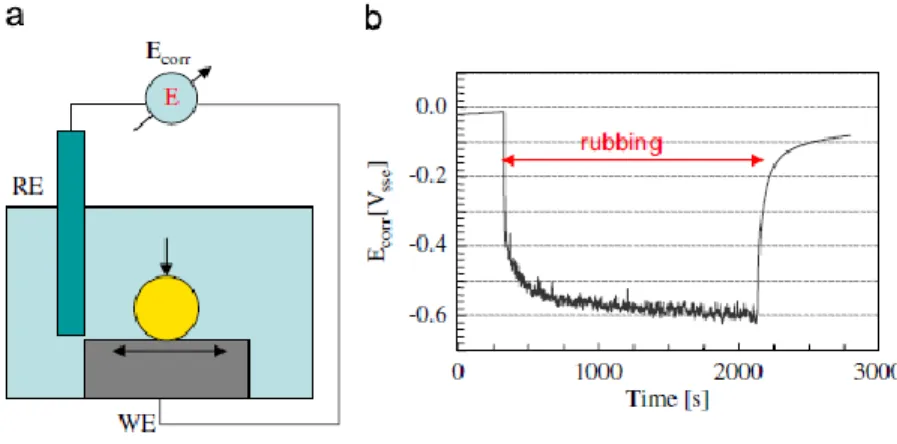
Figure 4 - a) Schematic view of a tribocorrosion experimental set-up for the corrosion potential technique and (b) Evolution of the potential of a Ti6Al4V alloy rubbing against an alumina ball in 0.9% NaCl solution. (WE: working electrode, RE: reference electrode) [70]... 16
Figure 5 - (a) Schematic view of a tribocorrosion experimental set-up for the potentiostatic tribocorrosion tests and (b) Evolution of the current of a Ti6Al4V alloy rubbing against an alumina ball in 0.9% NaCl solution at imposed potential of 0.3VSSE [70] ... 17
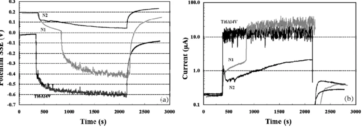
Figure 6 - Evolution of the potential a) and galvanic current b) during wear tests in OCP conditions for the untreated and plasma nitrided Ti6Al4V alloy (samples treated at 973 K are denominated N1 while samples treated at 1173 K are denominated N2) [72]. ... 18
Figure 7 - The evolution of the (a) OCP and (b) current density before, during, and after sliding [65]. ... 19
Figure 8 - Flowchart that summarize the methodology used in this thesis. ... 21
Figure 9 - Hot pressing procedure: a) painting of the die walls by zirconia, (b) introducing the powder, (c) applying the pressure, and (d) overall representation of the system [adapted from [73]]. ... 22
Figure 10 - RHP Thermal cycle. ... 23
Figure 11 - Corrosion test set-up [96]. ... 24
Figure 12 - Tribocorrosion test set-up. ... 25
Figure 13 - a ) XRD spectrum of the composite sample, b) secondary electron SEM image of the deep-etched composite sample together with the EDS spectra taken from the marked zones. ... 28
Figure 14 – Evolution OCP with time for Ti and its composite. ... 29
Figure 15 - Potentiodynamic polarization curves of Ti and its composite. ... 30
Figure 16 - SEM images of a, c) as-processed and b, d) corroded Ti and Ti-TiB-TiNx samples, respectively. ... 31
Figure 17 - (a) Nyquist and (b) Bode diagrams of experimental data and fitted curves for Ti and Ti-TiB-TiNx. ... 32
Figure 18 - Equivalent circuit used for fitting the experimental data of unreinforced titanium and composite samples. [68]. ... 33
Figure 19 - Evolution of COF under sliding, together with evolution of OCP before, during and after sliding in 9 g/l NaCl solution... 36
Figure 20 - Low magnification SEM images of the wear tracks from unreinforced and composite samples under different testing conditions. ... 37
Tribocorrosion behaviour of Ti−TiB−TiNx in-situ hybrid composite
xii Figure 21 - SE SEM images of the counter material surfaces worn against unreinforced and composite samples at different conditions, together with the EDS spectra taken from the wear scars. ... 38 Figure 22 - Higher magnification SEM images taken from inside of the wear tracks under different conditions. ... 40 Figure 23 - Schematic illustration of surface crack initiation mechanism on fatigue wear, together with the effect of oxide films on surface crack development (adapted from [90]). 41 Figure 24 - Wear track profiles... 42
xiii
List of Tables
Table 1 - Typical reinforcements used in MMCs [4]. ... 3 Table 2 - Mechanical properties of commonly used orthopaedic biomaterials [9]. ... 5 Table 3 - Particle reinforcements for MMCs [17]. ... 6 Table 4 - The properties Ti, together with TiB,TiB2, TiC, and TiN reinforcement materials
[26,28]. ... 7 Table 5 - Parameters of tribocorrosion tests. ... 25 Table 6 - ipass and E(i=0) values of Ti and its composite. ... 30
Table 7 - Equivalent circuit parameters obtained from EIS data in NaCl for Ti and Ti-TiB-TiNx. ... 33
xv
Abbreviations
MMC Metal matrix composite Ti Titanium
Ti6Al4V Titanium - aluminum – vanadium alloy Ti6Al7Nb Titanium - aluminum – niobium alloy CoCrMo Cobalt - chromium – molybdenum alloy CP Ti Commercially pure titanium
HP Hot pressing NaCl Sodium chloride OCP Open circuit potential COF Coefficient of friction D0,5 Medium particle size
SEM Scanning Electron Microscope RHP Reactive hot pressing
Al2O3 Alumina
XRD X-Ray diffraction OM Optical microscope HV Vickers hardness
EIS Electrochemical Impedance Spectroscopy PD Potentiodynamic Polarization
RE Reference electrode
SCE Saturated Calomel Polarization CE Counter electrode
icorr Corrosion current density
ipass Passivation current density
E(i=0) Corrosion potential
Rsol Electrolyte resistance
Rp Passive film resistance
Qox Capacitance of oxide film
CPE Constant phase element
TEM Transmission Electron Microscope XPS X-Ray Photoelectron Spectroscopy
Tribocorrosion behaviour of Ti−TiB−TiNx in-situ hybrid composite
1
Motivation and Objectives
Titanium and its alloys are being used in orthopaedic and dental implants due to their good mechanical properties, excellent corrosion resistance and good biocompatibility. Titanium and its alloys are also being used in automotive and aerospace industries due to combination of high stiffness and high temperature properties. However, poor wear and tribocorrosion resistance is a major concern for both biomedical and industrial applications. On biomedical implants case, tribocorrosion leads to the intense release of metallic ions and wear debris, with local and systemic harmful effects.
It is hypothesized that reinforcing titanium with in-situ ceramic phases can improve the tribocorrosion behaviour, increasing the lifetime of the parts where titanium is applied, particularly in biomedical applications. Thus, the main objective of this work was to produce and to triboelectrochemically characterise Ti−TiB−TiNx in-situ hybrid composites.
3
Chapter 1: Titanium Matrix Composites
1.1. Introduction
A material is considered as a composite material when combines two or more chemically and physically distinct phases where one is the matrix (major percentage of the material) and other is the reinforcement (dispersed phases in the matrix). A composite containing more than one type of reinforcement is defined as hybrid composite [1,2].
Metal matrix composites (MMCs) can be reinforced with various oxides, carbides, nitrides and borides in particulate, whisker or fiber form such as SiC, Al2O3, B4C, TiC, TiB2,
MgO, TiO2, AlN, BN and Si3N4, etc (Table 1) [2–4]. The success of the composite is strongly
influenced by chemical, mechanical and physical stability between reinforcement and matrix [1].
Table 1 - Typical reinforcements used in MMCs [4].
Type Aspect Ratio Diameter, µm Examples
Particle 1 – 4 1 – 25 SiC, Al2O3, BN, B4C, WC Short fiber or whiskers 10 – 10000 1 – 5 C, SiC, Al2O3, Al2O3 + SiO2
Continuous fibre >1000 1 - 150 SiC, Al2O3, C, B, W,
Nb-Ti, Nb3Sn 1.2. Titanium
Titanium and its alloys have many interesting properties for many applications in industry, such as low density, long fatigue life, excellent corrosion resistance, good chemical resistance, high hardness, high temperature resistance, good formability and excellent biocompatibility. However, Ti based materials have low wear and tribocorrosion resistance [5–7]. The incorporation of ceramic phases with high strength and high stiffness can improve drastically their mechanical and tribological performances [8].
One of the most important field for Ti-based materials is biomedical applications [9]. The metallic implants have significant economic and biomedical impacts. The worldwide market for all type of biomaterials was estimated at over $20 billion in 2000 and $23 billion in 2005,
Tribocorrosion behaviour of Ti−TiB−TiNx in-situ hybrid composite
4 and the rate of market growth estimated at about 12 to 20% per year. In United States, statistics showed that about 4.6% of the American population had at least one implant in 2000. Additionally, 152,000 total hip replacements performed in 2000 and it is estimated that this number will be increased up to approximately 272,000 by 2030 [10,11].
The design and selection of materials for biomedical applications depend on the intended medical applications. Biomaterials science is an interdisciplinary field requiring a collaborative effort between material scientists and engineers, biomedical engineers and medical doctors. An implant should have high fatigue strength and long fatigue life that determine the long-term success of the implant when subjected to cyclic loading. The implant should also have a low Young’s modulus, being close to that of cortical bone, in order to reduce the stress shielding effect. Others important point is the non-toxicity of the implant materials. Implant materials should not cause any inflammatory or allergic reactions in the human body. A good biomaterial depends on the reaction of the human body with the implant, i.e. biocompatibility.
Wear and corrosion resistance, or tribocorrosion resistance is also essential for the implant materials. If the biomaterial has a low tribocorrosion resistance, its presence in the body fluids results in releasing of non-compatible metal ions, causing allergic and toxic reactions. Finally, the implant should be able to integrate with the adjacent bone and other tissues that is defined as osseointegration [12–14].
CP Ti is the most commonly used material in dental implants due its high corrosion resistance, whereas Ti6Al4V alloy widely is used in orthopaedic applications due to its better mechanical properties when compared with CP Ti [9]. Table 2 shows the mechanical properties of commonly used biomaterials in orthopaedic implants. It can be seen that, generally, titanium and Ti6Al4V alloy have mechanical properties that exceed those of stainless steel. However the flexural rigidity of Ti and Ti6Al4V is lower than that of stainless steel and CoCrMo alloys. The torsional and the axial stiffness of Ti alloys are closer to those of bone than others metals, but they are sensitive to geometrical factors, particularly notch sensitivity, that reduces the effective strength of a component by increasing the susceptibility to crack propagation through the component. It has been considered that one of the biggest disadvantage of titanium and its alloys when compared with CoCrMo is their low wear
5 resistance and poor frictional properties. Therefore, the use of Ti alloys are restricted on the applications where the hardness or wear resistance is the primary concern [9].
Table 2 - Mechanical properties of commonly used orthopaedic biomaterials [9].
Orthopaedic biomaterial ASTM designation Young’s modulus (GPa) Yield strength (MPa) Ultimate strength (MPa) Fatigue strength (MPa) Hardnes s HVN Elongation at fracture (%) Cortical bonea Low strain 15.2 114t 150c/90t 30–45 — — High strain 40.8 — 400c– 270t — — — Polymers UHMWPE 0.5–1.3 20–30 30–40t 13–20 60–90 (MPa) 130–500 PMMA 1.8–3.3 35–70 38–80t 19–39 100–200 (MPa) 2.5–6 Ceramics Al2O3 366 — 3790c / 310t — ZrO2 201 — 7500c / 420t — — Metals Stainless steels 190 792 930t 241–820 130–180 43–45 Co–Cr alloys ASTM F75 210–253 448–841 655– 1277t 207–950 300–400 4–14 ASTM F90 210 448–1606 1896t 586–1220 300–400 10–22 ASTM F562 200–230 300–2000 800– 2068t 340–520 8–50 (RC) 10–40 ASTM 1537 200–300 960 1300t 200–300 41 (RC) 20 CP Ti ASTM F67 110 485 760t 300 120–200 14–18 Ti-6Al-4V ASTM 136 116 897–1034 965– 1103t 620–689 310 8 1.3. Reinforcements
The reinforcements in MMCs can be used in the form of continuous fibers, short fibers, whiskers, or particles. Continuous fibers have an aspect ratio of infinity while the aspect ratio of particles is around one [15,16]. The particle reinforcements are normally being chosen for economic reasons. Various oxides, nitrides, carbides, and borides that have been considered as particle reinforcements are given in Table 3 [17].
a Cortical bone is both anisotropic and viscoelastic thus properties listed are generalized.
Tribocorrosion behaviour of Ti−TiB−TiNx in-situ hybrid composite
6
Table 3 - Particle reinforcements for MMCs [17].
Metal-basis Carbide Nitride Boride Oxide
boron B4C BN - - tantalum TaC - - - zirconium ZrC ZrN ZrB2 ZrO2 hafnium HfC HfN - HfO2 aluminium - AlN - Al2O3 silicon SiC Si3N4 - -
titanium TiC TiN TiB2 -
chromium CrC CrN CrB Cr2O3
molybdenum Mo2C, MoC Mo2N, MoN Mo2B, MB -
tungsten W2C, WC W2N, WN W2B, WB -
thorium - - - ThO2
1.3.1. Titanium Nitride (TiN)
Nitrides belongs to the group of refractory materials and they are used as reinforcement in many applications. TiN has high hardness, high wear resistance and high electrical performance. Moreover TiN is chemically and thermodynamically stable and its melting point is 2950°C, which allows it to have high temperature resistance [18–21]. Besides, studies showed that TiN reinforced Ti-based composite structures exhibits excellent corrosion resistance and biocompatibility that makes it an ideal reinforcement for biomedical applications [22]
1.3.2. Titanium Boride (TiB)
TiB offers good advantages as reinforcement for titanium, such as high hardness, high corrosion resistance, thermal and chemical stability, formation of a clean interface and good bonding with Ti [23–25].The high elastic modulus, the possibility of obtaining a significant increase in strength and deformation resistance makes TiB an attractive reinforcement material. On the other hand, the coefficient of thermal expansion (CTE) of TiB is closer to that of Ti. Besides, the small density difference between Ti and TiB gives the possibility of increasing the volume fraction of TiB without affecting the density of the composite, significantly [26–28].
7 The properties of TiN and TiB are given in Table 4, together with Ti, TiB2 and TiC.
Table 4 - The properties Ti, together with TiB,TiB2, TiC, and TiN reinforcement materials [26,28].
Property/material Ti TiB TiB2 TiC TiN
Density (g/cm3) 4,5 4,56 4,52 4,92 5,43
Elastic modulus (GPa) 110 371 540 450 390
CTE at room temperature (×10-6/ºC) 8,2 7,15 6,2 7,95 9,35 Vickers hardness 150 1800 2200 3200 2300 Melting/decomposition temp. (°C) 1668 2200 2970 3054 3220 1.4. Processing techniques
Titanium matrix composites can be processed by liquid, solid or gaseous state processing routes [29–32]. Solid state routes such as powder metallurgy and hot pressing are being commonly used for MMCs due to the ease of obtaining a homogenous distribution of the reinforcements and avoiding the detrimental reaction products that are likely to occur at high processing temperatures of the liquid-state routes [33].
As an essential step for the solid-state processing routes, sintering is the consolidation process with the heat treatment below the melting temperature of the matrix metal. During sintering, solid-solid interfaces are formed, and mass transport to the pores normally leads to shrinkage and densification [34]. The hot pressing technique, consisting in heating and pressing simultaneously, promotes compaction and densification at high temperatures and the pores or voids simply collapse under axial deformation [35,36]. The densification process under the action of the pressure can be represented through the mechanism of material transport that involves sliding of whole particles along their boundaries by changing their shape in order to adapt themselves to the shapes of their nearest neighbours, and counter this impeding action of obstacles [37]. Thus, hot pressing technique involves plastic deformation, creep and diffusion mechanism to cause localized flow of material into the pores [36]. Reactive hot pressing (RHP) is a processing method for in-situ composites where thermodynamically favourable reactions form intermetallic and non-oxide ceramic
Tribocorrosion behaviour of Ti−TiB−TiNx in-situ hybrid composite
8 reinforcements by a solid-state diffusion-controlled process. RHP process allows to control the reactions whereas simultaneous application of pressure allow to obtain dense specimens [38]. Moreover, the technique also allows to adjust the volume fraction of the reinforcements and particle size along with the strict control of particle distribution via initial blending and subsequent thermomechanical deformation, resulting in improvement of some properties such as ductility, toughness and fatigue [2,39,40].
1.5. In-situ composites
An in-situ composite is a material class that uses reactions in different components during the processing. In-situ process is divided into two categories, namely reactive and non-reactive. In the reactive processes, the components react exothermically to form the reinforcement phases. In the non-reactive processes, a two phase system is formed by eutectic and monotectic alloys to form fibres and in-situ matrix [40,41].
In the reactive processes, the reaction between components can happen both during mixing the powders and in the subsequent processing. However, a minimum induced energy is needed to get the reaction going. This process can take place with thermal energy of hot pressing or by high kinetic energy obtained in the case of the mechanical alloying [5].
In-situ composites present 'clean' interfaces, no detrimental reactions products, no interfacial discontinuities and usually stronger interfaces [42]. Furthermore, in-situ phases are normally finer in size and their distribution in matrix is more uniform, resulting in better mechanical properties [41,43].
A wide range of in-situ MMCs have been developed with different matrix materials like aluminium, titanium, copper, nickel and iron with the second-phases such as borides, carbides, nitrides, oxides and their mixtures [43].
9 1.6. The Ti-BN system
Z.L. Yang et al. [44] presented a thermodynamic consideration on the Ti−BN system. The possible reactions that can occurs in Ti−BN system are given in Figure 1. The thermodynamically favourable and exothermic reactions are reactions (1), (2), (3) and (8), since they have Gibbs free energy values below zero (ΔG<0). The authors reported that TiN and TiB2 are the most favourable reaction products in the Ti−BN system since the reaction
(1) has the most negative ΔG values. However, it has been reported that in the presence of excess Ti, more specifically, if the average B concentration in the reaction zone is less than 18% in mass fraction, TiB2 transforms to TiB at elevated temperatures [45,46].
Combination of the reinforcing phases of TiB and TiN offers to improve the wear resistance of Ti owing to their high hardness, excellent thermal and chemical stability and corrosion resistance [24,27,47]. However, the tribocorrosion behaviour of in situ Ti−TiB−TiN MMCs is yet to be studied.
Figure 1 - Calculated standard Gibbs energy changes in potential reactions for the Ti -BN system at different temperatures. b) Possible reactions in Ti−BN system [adapted by 44].
11
Chapter 2: Degradation of Titanium
Matrix Composites
2.1. Introduction
Material degradation can be defined by the loss of properties, thus, performance of materials in an engineering system. It has been reported that materials degradation can cause capital loss of 5% a year corresponding to values between $100 billion to $1 billion a year [48]. 10% of the material degradation in engineering parts attributed to corrosion, while 30% is due to abrasion, 15% is due to adhesion and 10% is duo to Tribocorrosion [49].
2.2. Degradation due to wear
Wear is defined as the progressive loss of a material due to mechanical interaction between two contacting surfaces [50].
The two most common wear mechanisms are adhesive wear and abrasive wear. However there are other mechanisms involved such as tribochemical reactions, fatigue wear and delamination wear [50,51].
The adhesive wear can occur during a relative motion between two smooth surfaces. The fragments generated by the movements are pulled off from one surfaces and adhere to other one [52]. On the other hand, abrasive wear occurs when a rough surface or soft surface containing hard particles is sliding against another surface, resulting in ploughs and series of grooves on the worn surfaces. The abrasion damage appears like regular patterns of scratches (two body abrasion). [52] When wear is caused by particles confined within the two sliding surface areas, the wear mechanism in known as three-body abrasion [50,51].
Foure et al. [53] studied the dry sliding wear behaviour of Ti6Al4V alloy under different sliding velocities. The authors concluded that when sliding velocity increased, there was an increase on friction. The effect of friction heating during sliding leads to a softening of the surface. As a result, adhesive wear and abrasive wear took place on the worn surface.
Tribocorrosion behaviour of Ti−TiB−TiNx in-situ hybrid composite
12 In the literature, numerous studies that are using Ti with several reactants to produce in-situ composites were aimed development of ceramic matrix composites. Furthermore, most of studies were focused on structural and microstructural characterization of in-situ composites whereas the studies on the wear behaviour is very limited. Y. Qin et al [54] studied the dry sliding wear behaviour of TiB and TiC reinforced Ti−MMCs processed by reactive hot pressing followed by extrusion. After the dry sliding wear tests performed against a tool steel counter material by using a pin-on-disk tribometer, the authors reported that in-situ ceramic phases significantly improved the wear resistance of pure Ti, as well resulted in lower coefficient of friction (COF). The similar system (Ti−TiB−TiC) produced by lost-wax method was also studied by I.Y.Kim et al. [55] against a 52100 bearing steel ball by using ball-on-disk tribometer, where lower wear loss and COF values was also reported. J.S. Kim et al. [56] recently studied the fretting behaviour of Ti−TiB−TiC MMCs against a bearing steel ball specimen and reported that the wear volume decreased with the increased volume fraction of the hard ceramic phases.
The previous study [57] investigated the dry reciprocal sliding wear behaviour of in-situ Ti−TiB−TiNx composites, in comparison with rolled titanium (Ti) and hot pressed titanium
(HP Ti) against a 10mm diameter of alumina ball under 10 N normal load, with 1 Hz frequency, 3 mm stroke length and 30 min sliding time. The results showed that the dry sliding wear resistance significantly increased by incorporation of TiB and TiNx phases. As
it can be seen on Figure 2, the wear volume loss of the composite samples were about 5 times lower than the one that of the as-rolled Ti.
13 Figure 3 presents the SEM images of the wear tracks. It can observed that the composite samples presented the smallest wear track. However the wear mechanisms on the three materials was reported as mainly the combination of abrasive, adhesive, and oxidative wear for the as-rolled and HP Ti samples whereas the mechanism was mainly as a combination of abrasive and adhesive wear for the composite samples [57].
Figure 3 - SEM image of the wear tracks: a) As-rolled Ti; b) HP Ti; c) Ti-TiB-TiNx composite [57].
Figure 2 - Wear volume loss values of as-rolled Ti, HP Ti and Ti-TiB-TiNx after dry sliding wear tests [57].
Tribocorrosion behaviour of Ti−TiB−TiNx in-situ hybrid composite
14 2.3. Degradation due to corrosion
Corrosion is defined by D. Landolt [58] as “an irreversible interfacial reaction of a material with its environment resulting in the loss of material or in the dissolving of one of the constituents of the environment into the material”
The corrosion behaviour can be influenced by the chemical composition and the microstructure of the metal, type of the environment, physical parameters and mechanical forces ( tensile stresses, shocks or friction) [58].
Titanium has high affinity to oxygen and forms a thin, very stable, protective and strongly adherent passive oxide layer [59–61]. In the presence of such an oxide film, the dissolution rate of the passive metal at given potential is much lower than that of an active material. The dissolution rate depends on the properties of the passive film and its solubility in the solution. During the transition from active to the passive state, the rate of dissolution decreases dramatically [58]. On the other hand, this oxide layer also plays an important role on the bio-compatibility of titanium implants [62].
Cai et al. [63] studied the in-vitro corrosion behaviour of CP Ti and cast Ti alloys (Ti6Al4V, Ti6Al7Nb, Ti13Nb13Zr) with three different surface conditions (sandblasted, polished surface after removal of the reaction layer and sandblasting after removal of the reaction layer), in modified Tani-Zucchi synthetic saliva at 37°C. The results indicated that both CP Ti and Ti alloys presented excellent corrosion resistance. However, the surface condition had stronger effect on the corrosion behaviour of these alloys than the surface reaction layer.
Kuphasuk et al. [64] compared the corrosion behaviour of Ti and alloys (unalloyed Ti, Ti6Al4V, NiTi, Ti4.5Al3V2Mo2Fe, Ti5Al2.5Fe, Ti5Al3Mo4Zr) by electrochemical polarization tests at 37°C, in Ringer’s solution. The authors concluded that all samples presented good resistance to corrosion over the potentials of relevant intraoral conditions, whereas CP-Ti and Ti5Al2.5Fe were reported as the most resistant to corrosion. All tested samples at 37°C in Ringer solution were mainly covered by a layer of rutile (TiO2).
15 In MMCs, the corrosion behaviour can be significantly influenced by different parameters, such as chemical composition of the matrix and reinforcement phases, residual stresses, microcrevices, porosity, interaction products and secondary phase precipitates. The corrosion in MMCs occurs mainly due to galvanic coupling between the matrix and the reinforcement materials, selective corrosion at the matrix/reinforcement interface, chemical degradation of the interphases and the reinforcement materials, and corrosion of the matrix defects [65].
In the literature, there is limited information about the corrosion behaviour of titanium matrix composites. Lavrenko et al. [66] studied the kinetics and mechanism of electrolytic corrosion of hot isostatic pressed titanium based ceramics (TiN−AlN, TiB2−AlN, TiB2−TiN
and TiC0.5N0.5) by anodic polarization in 3% NaCl solution containing Mg2+ ions as additive
at 20°C. The authors concluded that the electrolytic corrosion of titanium matrix composite is a multistep process. After an initial anodic dissolution, with transfer of Ti3+, TiO2+ and H3BO3 into the solution, the formation of TiNxOy, TiCxNyOz or rutile partially protecting
layers took place; this latter oxide slows down the dissolution of the composites. Besides, the authors reported that the studied materials presented three-four orders lower corrosion rates than that of majority of metallic materials such as low carbon steels, stainless, etc.
Alkhateeb et al. [67] studied the electrochemical evolution of the corrosion behaviour of titanium-based ceramic coating layers (TiN, TiB2 and Ti−BN with different boron content)
by potentiodynamic polarization and electrochemical impedance spectroscopy method in a 0.5M NaCl solution. It was showed that the steel coated with TiB2 and TiBN with a boron
content of 20% presented the best corrosion resistance.
Valente et al. [60] investigated the corrosion behaviour of reactive plasma sprayed titanium−titanium nitrides coatings in a neutral solution (0,5 M NaCl) and acid solution (0,5 M NaCl + 1 M HCl). The authors reported that the corrosion behaviour of titanium−titanium nitrides coatings was strictly dependent on the coating porosity and that the corrosion resistance of titanium-based coatings were always lower than that of the bulk titanium.
Tribocorrosion behaviour of Ti−TiB−TiNx in-situ hybrid composite
16 2.4. Degradation due to tribocorrosion
Tribocorrosion is a research area that combines tribology and electrochemistry [68]. Tribocorrosion is defined by Landolt et al. [69] as “an irreversible transformation of a material resulting from simultaneous physic-chemical and mechanical interactions that occur in a tribological contact”.
Tribocorrosion can be characterized by the synergism resulting as consequence of simultaneous action of wear and corrosion where the degradation rate can be different from that estimated from the sum of corrosion rate of the wear rate measured individually [68].
The most commonly used electrochemical techniques for the tribocorrosion tests are corrosion potential technique and potentiostatic technique. The corrosion potential technique consist in monitoring the potential difference between the testing samples and a reference electrode placed in the solution close to the samples [70]. As showed in Figure 4b, when rubbing action started, the corrosion potential of the passive titanium alloys shift to lowers values. During rubbing, the measured corrosion potential is a combination of two distinct surfaces states of the material: unworn and worn areas. After stopping the sliding, depending on the characteristics of material/electrolyte interface, the potential values may increase up to near the initial values due to repassivation [70].
Figure 4 - a) Schematic view of a tribocorrosion experimental set-up for the corrosion potential technique and (b) Evolution of the potential of a Ti6Al4V alloy rubbing against an alumina ball in 0.9% NaCl solution. (WE: working
17 On potentiostatic tribocorrosion tests (Figure. 5 (a)), a selected potential is applied to the metallic samples by using a three electrode set-up including the working electrode (the sample), the reference electrode and the counter electrode. The three electrodes are connected to a potentiostat that maintains the selected potential between working and reference electrodes by passing an appropriate current between working and counter electrodes. The current is measured at fixed potential as a function of time to follow the evolution of the electrochemical kinetics of the involved reactions. As can be seen on Figure 5 (b), when rubbing starts, the measured current values increase due to the removal of the passive film, indicating an increased corrosion rate. When rubbing stops, depending on the characteristics of the material/electrolyte interface, repassivation may occur, thus the values may decrease near the initial values [70].
Figure 5 - (a) Schematic view of a tribocorrosion experimental set-up for the potentiostatic tribocorrosion tests and (b) Evolution of the current of a Ti6Al4V alloy rubbing against an alumina ball in 0.9% NaCl solution at imposed potential of
0.3VSSE [70]
On potentiostatic tribocorrosion tests, applied potential can be selected as corrosion potential, a cathodic potential or an anodic potential. At the corrosion potential, anodic and cathodic reactions occur at the same rate, thus the current is measured as zero. At the cathodic applied potentials, the measured current is determined by the kinetics of the cathodic reactions. The tribocorrosion experiments performed under cathodic applied potentials can
Tribocorrosion behaviour of Ti−TiB−TiNx in-situ hybrid composite
18 be considered as representing the wear due to the mechanical action (rubbing) together with the lubricant effect of the solution, since the metal dissolution rate is negligible. At anodic potentials, on the other hand, the measured current is determined by the kinetics of the metal oxidation [70,71].
Galliano et al. [72] investigated the tribocorrosion behaviour of plasma nitrided Ti6Al4V alloy in a 0.9 M NaCl solution at room temperature. The authors concluded that TiN layer on the surface improved the tribocorrosion resistance in a neutral saline solution, as it is presented in Figure 6, by higher potential values and lower galvanic values under sliding.
To the best of our knowledge, there is no study in the literature on the tribocorrosion behaviour of titanium matrix composites. However, there are studies on the other MMCs showing the possibilities of improving the tribocorrosion behaviour by reinforcing a passive metal matrix with hard ceramic phases. Toptan et al. [65] studied the tribocorrosion behaviour of Al-alloy matrix B4C reinforced composites against an alumina ball in 0.05 M
NaCl solution. The evolution of OCP and current density before, during and after sliding is given in. Figure 7. As can be seen on the graphs, as opposite to the unreinforced alloy, composite samples presented an increase on the potential and a decrease on the current density values under sliding, indicating a lower tendency and lower corrosion rate under sliding. The authors attributed this behaviour to a mechanism where the counter material was
Figure 6 - Evolution of the potential a) and galvanic current b) during wear tests in OCP conditions for the untreated and plasma nitrided Ti6Al4V alloy (samples treated at 973 K are denominated N1 while samples treated at 1173 K are
19 sliding mainly on B4C particles, which protected the matrix alloy from severe corrosion/wear
damage. Thus, the tribocorrosion behaviour was improved with the hard ceramic particle addition.
21
Chapter 3: Materials and Methods
3.1. Materials
Testing samples (unreinforced Ti and Ti composites) were produced using commercially pure titanium (CP Ti) powders (Alfa Aesar) and Boron Nitride (BN) powders (Sigma – Aldrich) both in angular shape and having 28.8 and 1 µm average particles sizes, respectively.
3.2. Methods
The purpose this thesis was study the tribocorrosion behaviour of Ti−TiB−TiNx in-situ
composite. Figure 8 presents the flowchart that summarize the methodology that was followed in this work.
Figure 8 - Flowchart that summarize the methodology used in this thesis.
3.2.1. Mixing
Particles blends having 23:1 Ti:BN weight ratio were ball milled at 25 rpm speed during 3h using alumina balls. Prior to the processing, powder mixtures were dried in a muffle furnace at 105ºC for 1h in order to remove the humidity.
Tribocorrosion behaviour of Ti−TiB−TiNx in-situ hybrid
composite
22
3.2.2. Processing
The samples were processed by reactive hot pressing technique (RHP). The schematic representation of the RHP process is given in Figure 9. The powders were insert into a graphite die having 10 mm of inner diameter. The die walls were painted with zirconia paste to avoid the contamination and to prevent diffusion of carbon. The die was mounted into a hydraulic press and heated up to 1100°C with the heating rate of 10°C/min. The entire process was performed under 10-2 mbar vacuum, 40 MPa constant pressure with a sintering time of 30 min. The temperature was monitored during the whole process, using a type K thermocouple connected to a data logger (National Instruments – NI SCXI-1000). The thermal cycle is given in Figure 10.
Figure 9 - Hot pressing procedure: a) painting of the die walls by zirconia, (b) introducing the powder, (c) applying the pressure, and (d) overall representation of the system [adapted from [73]].
23
3.2.3. Chemical, Microstructural and Physical Characterization
After processing the samples were ground down to 2400 mesh SiC paper followed by polishing with a colloidal silica suspension (0,04 µm). Finally, the samples were cleaned ultrasonically with propanol during 10 min followed by distilled water during 5 min. In order to obtain the similar surface conditions, each sample was kept in a desiccator for 24 h before starting the electrochemical and triboelectrochemical tests.
The structural analysis of the in-situ composites was determined by X-Ray diffraction (XRD; Cu Kα radiation, Brunker D8 Discover).
The microstructures of in-situ composites were characterized, after a deep etching with Kroll’s (H2O-HF-HNO3), by FEI Nova 200 Field Emission Gun Scanning Electron
Microscope (FEG-SEM) equipped with Dispersive X-Ray Spectroscopy (EDS).
Corroded and worn surfaces were also characterized using Leica DM2500 optical microscope (OM) and FEG-SEM/EDS. All worn surface images were taking as parallel to the sliding direction.
Vickers macro-hardness values were measurement by a mean of 3 indentations per sample at a 30 Kg with dwelling time of 20 s by using Officine Galileo Mod. D 200 tester.
0 200 400 600 800 1000 1200 0 2000 4000 6000 8000 10000 12000 14000 Tem p e ratu re ( °C) Time (s)
Tribocorrosion behaviour of Ti−TiB−TiNx in-situ hybrid
composite
24
3.2.4. Corrosion Tests
Electrochemical tests consist in open circuit potential (OCP), electrochemical impedance spectroscopy (EIS) and potentiodynamic polarization (PD). All tests were carried out in a 9 g/l NaCl solution at 37 ± 2ºC using Gamry Potentiostat/Galvanostat (model Referece-660).
The electrochemical tests were performed using a standard three-electrode electrochemical cell (adapted from ASTM: G3-89) with an electrolyte volume of 180 ml. Saturated calomel electrode (SCE) used as the reference electrode, Pt electrode used as the counter electrode, and the samples having an exposed area of 0.34 cm2 used as the working electrode (Figure 11).
Both EIS and PD measurements were performed by using an initial delay time at equilibrium state of 120 min in order to stabilize the surface at OCP. The polarization scan was performed in anodic direction, starting at 0.9 V to 1V with a scanning rate of 1 mV/s.
In the EIS measurements, the data acquisition was done by scanning a rage of frequencies from 65 kHz till 10 mHz with 10 points per frequency decade, and the amplitude of the sinusoidal was ± 10 mV, in order to guarantee linearity of the electrode response.
25
3.2.5. Tribocorrosion Tests
For the tribocorrosion tests, the electrochemical cell was mounted on a ball-on-plate tribometer (CETR-UMT-2) with a reciprocating plate adapter having the working surfaces facing upwards, against the counter material (10 mm diameter alumina ball, Ceratec), as shown in Figure 12.
The electrochemical measurements (OCP) were carried out at 37 ± 2°C using the same electrode setup and 30 ml the same solution that used in the corrosion tests. The OCP monitored before, during and after sliding where the sliding started after reaching stable OCP values. All electrochemical measurements were performed using a Voltalab PGP201 potentiostast. The tribological parameters that were used on the tribocorrosion tests were given in Table 6. After the tribocorrosion tests, five 2D profiles were taken from each wear track using a non-contact profilometer (Veeco Dektak).
Table 5 - Parameters of tribocorrosion tests.
Load (N) Maximum Initial
Hertzian Contact Pressure (MPa) Total stroke length (mm) Frequency (Hz) Time (s) 1 10 410 890 3 3 1 and 2 1 1800 1800
27
Chapter 4: Results and Discussion
4.1. Chemical, Microstructural and Physical Characterization
J. Li et al. [74] investigated the microstructure evolution on Ti/BN powder blends having 3:2 Ti to BN molar ratio and reported after DSC analysis that TiN phase forms between 300−500°C, whereas TiB2 and TiB phases form at the temperature range of 500−900°C. On
the other hand, as stated above, in the presence of excess Ti, TiB2 transforms to TiB at
elevated temperatures [75,76]. Furthermore, Z.-L. Yang et al. [44] reported for the Ti−BN system that N atoms dissolve into the α−Ti as interstitials and form α−TiN0.3. Then, N atoms
from BN react with α−TiN0.3 and form Ti2N and substoichiometric TiNx. Above 1100°C,
Ti2N transforms to TiNx where as more N atoms diffuse into the TiNx phase, its composition
becomes close to stoichiometric TiN. As can be seen on the XRD spectrum given in Figure 13a, the composites exhibited TiB and TiNx in-situ reinforcement phases, as in accordance
with the literature. On the other hand, it is known that B atoms have faster diffusion rates in the [010] direction as compared to the other directions, resulting in a needle-like morphology for the TiB phase [77,78]. In accordance with the literature [24,79], TiB whiskers were clearly observed on the SEM images of the deep-etched composite samples (Figure 13b). However, although TiNx phase was detected by XRD and the presence of N was found by
EDS, TiNx phase was not visible on the SEM images probably due to its finer structure [74].
Thus, further characterization studies (i.e. TEM) are needed for microstructural characterization of TiNx phase.
Tribocorrosion behaviour of Ti-TiB-TiNx in-situ hybrid composite
28
Figure 13 - a ) XRD spectrum of the composite sample, b) secondary electron SEM image of the deep-etched composite sample together with the EDS spectra taken from the marked zones.
Macro hardness of titanium and Ti−TiB−TiNx in-situ composite were measured. Results showed that the composite presented a high hardness (718 ± 22) as compared to the unreinforced titanium (345 ± 16), presenting more than double the value which indicate that with the formation of the in-situ TiB and TiNx phases, the hardness significantly increased.
29 4.2. Corrosion behaviour
Open circuit potential (OCP):
OCP gives information on the electrochemical state of a material in contact with an electrolyte, for example if a metal is in active or passive state. However, this technique gives limited information about the kinetics of the reactions [80]. Figure 14 gives the evolution of OCP with time for Ti and its composite. As can be observed on the graph, both Ti and its composite presented similar evolution. A slightly increase on potential values through time was noticied, that can be attributed to the formation of a protective layer on the surface. However, no significant differences were noticed on the corrosion potential values between Ti and its composite.
Figure 14 – Evolution OCP with time for Ti and its composite.
Potentiodynamic polarization:
Potentiodynamic polarization measurements is the most useful method to determine the active/passive behaviour of the material at different potentials [80]. Figure 15 shows the potentiodinamic polarization curves of Ti and composite samples and Table 6 gives the
Tribocorrosion behaviour of Ti-TiB-TiNx in-situ hybrid composite
30 average passivation current density (ipass) and corrosion potential E(i=0) values obtained by
Tafel extrapolation method. It can be observed from polarization curves that the two materials exhibit similar behaviour. In anodic domain, both materials presented a well-defined passivation plateau due to the formation of the passive oxide film. Since both materials presented similar polarization behaviour, together with E(i=0) and ipass values, it can
be stated that the formation of TiB and TiNx in-situ phases did not significantly affect the
corrosion behaviour of Ti.
Figure 15 - Potentiodynamic polarization curves of Ti and its composite.
Table 6 - ipass and E(i=0) values of Ti and its composite.
ipass (×10-6A.cm-2) E(i=0) (mV)
Titanium 4.35 ± 0.46 -429 ± 40
Ti-TiB-TiNx 4.33 ± 0.71 -478 ± 34
Figure 16 presents the SEM images before and after corrosion tests for Ti and Ti−TiB−TiNx. As can be seen on the images, no clear difference was observed on the samples
31
Figure 16 - SEM images of a, c) as-processed and b, d) corroded Ti and Ti-TiB-TiNx samples, respectively.
Electrochemical impedance spectroscopy (EIS)
Figure 17 presents the EIS diagram in the form Nyquist and Bode. Nyquist diagram can be evaluated by comparing the diameters of the semi-circles where larger diameter indicates a better corrosion resistance [62]. As can be observed in Nyquist diagram (Figure17 (a)) the composite samples presented a slightly larger diameter of the semi-circle when compared to the Ti samples, thus it can be stated that Ti-TiB-TiNx presented a slightly higher polarization
resistance.
The Bode diagram , Figure 17 (b) shows constant values of |Z| in high frequency range (1000 Hz to 10 kHz) where phase angle is near to 0º corresponding to the electrolyte
(c) (d)
Tribocorrosion behaviour of Ti-TiB-TiNx in-situ hybrid composite
32 resistance [62]. A high capacitive behaviour, typical and stable of behaviour of a passive material, is indicated from medium to low frequencies by phase angles approaching to −90° [81]. As can be observed in Bode diagram, in low and middle frequency rage, the phase angle presented values that approach to −90°C for both materials as the typical capacitive behaviour of a compact oxide film.
Figure 17 - (a) Nyquist and (b) Bode diagrams of experimental data and fitted curves for Ti and Ti-TiB-TiNx.
The impedance spectra for all samples tested were fitted to the equivalent circuit using Gamry Echem Analyses software (version.5.61) and the quality of the fitting was evaluated through their goodness of fitting values. The equivalent circuit for native oxide film formed on surfaces of Ti and Ti−TiB−TiNx samples exposed to NaCl solution, which was used fitting
of the experimental data, contains: electrolyte resistance, Rs, native oxide film resistance, Rnof,
and constant phase element (CPE), Qnof, accounting for the non-ideal capacitance of the native
oxide film (Figure 18).
The constant phase element impedance, CPE, is defined as 𝑍𝐶𝑃𝐸 = [𝑌0(𝑗𝑤)𝑛]−1,
where−1 ≤ 𝑛 ≤ 1. When 𝑛 = 1, 𝑛 = 0 and 𝑛 = −1, the CPE responses corresponds to those of a capacitor, a resistor or an inductor, respectively. When 𝑛 ≈ 1, a non-ideal capacitor may be described by this element the 𝑛 value is being influenced by the roughness of the surface and its heterogeneity [82]. All samples presented range of 𝑛 values between 0.90 and 0.94,
(b) (a)
33 thus the proposed model describes adequately the behaviour of the native oxide film in contact with NaCl, with goodness of fitting below 1×10⁻⁴.
Figure 18 - Equivalent circuit used for fitting the experimental data of unreinforced titanium and composite samples. [68].
Table 7 gives the equivalent circuit parameters obtained from EIS data for Ti and Ti−TiB−TiNx. No significant differences were observed on Qnof values between Ti and
composite samples, suggesting a very similar insulating character of the passive layer formed on the surfaces. However, a slight increase on the native oxide film resistance (Rnof) was
observed on the composite samples, suggesting a slightly higher quality for the passive layer formed on the composite surface.
Table 7 - Equivalent circuit parameters obtained from EIS data in NaCl for Ti and Ti-TiB-TiNx.
4.3. Tribocorrosion behaviour
In order to investigate the effect of the normal load and the sliding frequency to the tribocorrosion behaviour of the in-situ composites, the tests were performed under two different levels of load and sliding frequency. Normal loads were selected as 1 N, corresponding to maximum initial Hertzian contact pressure of 280 MPa, in order to avoid the plastic deformation by the static load, and as well 10 N, corresponding to maximum initial Hertzian contact pressure of 600 MPa, in order for testing the extreme conditions, as well, to compare the results with the dry sliding wear tests that were performed in the previous study
Rnof (x106 Ω.cm2) Qnof (x10- sn. Ω-1.cm-2)
Titanium 1.25 ± 0.22 1.82 ± 0.32
Tribocorrosion behaviour of Ti-TiB-TiNx in-situ hybrid composite
34 [57]. Besides, since the implant materials can be subjected to different sliding frequencies, two levels of sliding velocity, namely 1 and 2 Hz were applied.
The representative evolution of OCP before, during, and after sliding is given in Figure 19, together with the evolution of coefficient of friction (COF). Three different zones can be distinguished on the evolution of the OCP of all samples in all conditions. Before sliding, the OCP values were stable due the presence of a passive film on the sample surfaces in contact with the NaCl solution [73,83]. When sliding started, a sudden drop on OCP values were recorded indicating an increase on the thermodynamic tendency to corrosion due the mechanical damage of the passive film and the formation of the active zones located in the wear tracks [84]
Regarding the unreinforced material, on the onset of the sliding, a very similar cathodic shift was observed for all testing conditions. All samples of titanium reached around the potential values of −0.6 V. Unlike other testing conditions, the OCP values were slightly increased during the sliding for unreinforced alloy tested under 1N-1Hz. Besides, Ti tested under 10 N presented relatively larger oscillations on the OCP values during sliding. After sliding, OCP values for all unreinforced samples increased up the near the initial values due to the recovering of the passive film.
The composite sample tested under 1N of load and 1Hz of frequency presented a very small potential drop (approx. 45 mV) at the onset of the sliding and the values were increased almost up to the values during sliding. When the sliding frequency increased, potential drop at the onset of the sliding significantly increased by reaching the values around −0.4 V, but even so, the OCP values under sliding were always significantly higher than the unreinforced Ti tested under the same conditions. In the case of 10N, the composite sample exhibited similar potential values as the unreinforced sample. Similar to the unreinforced samples, after sliding, OCP values were increased up the near the initial values.
Evolution of COF is also given in Figure 19. When compared to the unreinforced samples on different conditions, it is possible see that as soon as the sliding started, COF values were suddenly reached to the values around 0.4 for all samples. During sliding, COF values of the samples tested under 1 N-1 Hz maintained around the 0.4 around approx. first 1000 s and
35 after this, local increments were observed on the values whereas the other unreinforced samples remained relatively stable till the end of the sliding.
Regarding the composite samples, when sliding started, COF values were rapidly reached the values around 0.6 for all conditions. During sliding, the values were relatively stable, however, larger oscillations were observed for the sample tested under 1 N-2 Hz.
Tribocorrosion behaviour of Ti-TiB-TiNx in-situ hybrid composite
36
v
A) 1 N – 1 Hz B) 1 N – 2 Hz C) 10 N – 1 Hz
Figure 19 - Evolution of COF under sliding, together with evolution of OCP before, during and after sliding in 9 g/l NaCl solution.
37 Figure 20 presents the low magnification SEM images of the wear tracks. As can be seen on the images, composite samples presented thinner wear tracks as compared to the unreinforced samples, except on sample tested with 10 N of load and 1 Hz of frequency, which presented slightly the opposite. Besides, parallel sliding grooves and tribochemical features can also be seen on the images presented in secondary electron (SE) and backscattered electron (BSE) modes, respectively. In the case of unreinforced titanium, it was observed that oxide patches formed and the grooves were more intensive on the samples tested under 10 N. On the other hand, the thickness of the wear track increased when the frequency or the load increased. Moreover, it was also observed on the composite samples that the samples tested under 1 N (both for 1 Hz and 2 Hz) compact oxide layers were formed on the wear tracks, however, this was not observed on the sample tested under 10 N of load.
Ti Ti-TiB-TiNx 1 N – 1 H z 1 N – 2 H z 1 0 N – 1 H z
Figure 20 - Low magnification SEM images of the wear tracks from unreinforced and composite samples under different testing conditions.
Tribocorrosion behaviour of Ti-TiB-TiNx in-situ hybrid composite
38 Figure 21 presents the SE SEM images of the worn counter material (Al2O3 ball) surfaces
and the EDS spectra taken from the wear scars. The wear scars on the ball corresponding to the unreinforced samples were bigger whereas the dominant feature was observed as adhesion. When compared the different conditions, it was possible to observe that the adhesion was more evident on the samples tested under 10 N of load for both materials (titanium and composite), and it was lower on the samples tested under 1 N of load and 1 Hz of frequency.
Against Ti Against Ti-TiB-TiNx EDS Spectra
1 N – 1 Hz 1 N – 2 Hz 10 N – 1 Hz
Figure 21 - SE SEM images of the counter material surfaces worn against unreinforced and composite samples at different conditions, together with the EDS spectra taken from the wear scars.
39 The topography and the features of the worn sample surfaces can be seen more clearly on the higher magnification images taken from inside of the wear tracks (Figure 22). Worn surfaces of all unreinforced samples exhibited oxide patches. Titanium oxides may form on the worn surfaces due to the repetitive material transfer between the sliding surfaces resulting in formation of adhered/mixed oxide patches [73,85,86]. Oxidational wear describes a wear mechanism where oxide films are formed at the contact area due to the elevated temperature at the sliding zone. It is known that these oxides can play a protective role during sliding of metallic materials. However, when the oxide layers reach a critical thickness, they can break up resulting in formation of oxide wear debris [87–89]. As can be seen on the unreinforced samples, although the oxide patches covered a relatively higher area fraction on the worn surfaces, it was not a continuous layer, thus, could not completely avoid the contact of the counter material with the Ti surface, resulting in grooves and material transfer to the counter material. Moreover, the unreinforced samples tested under 10 N presented more compacted oxide patches and severe plastic deformation. Worn composite surfaces, on the other hand, exhibited relatively thick compacted wear debris under 1 N. A compacted wear debris layer was not observed on the worn surfaces of the composite samples tested under 10 N, probably due to do higher load that did not allow formation of a compact layer. Moreover, since oxidized wear debris could not form a compacted layer, they freely moved on sliding surface creating third-body abrasion resulted in sliding grooves [90].
Tribocorrosion behaviour of Ti-TiB-TiNx in-situ hybrid composite 40 Ti Ti-TiB-TiNx 1N - 1 Hz 1N - 2Hz 10N - 1Hz
Figure 22 - Higher magnification SEM images taken from inside of the wear tracks under different conditions.
Cracks and fissures were observed on all worn unreinforced sample surfaces, whereas, on the composite samples, cracks were only observed on the samples tested under 10 N (Figure 22). These cracks can be generated by fatigue wear. Figure 23 presents a schematically illustrated mechanism of surface crack initiation on fatigue wear proposed by Stachowiak and Batchelor [90]. As can be seen on the figure, a primary crack may originate at the surface at some weak point and may propagate downward along weak planes such as slip planes or dislocation cell boundaries. Moreover, as cracks propagate, fresh surfaces coming in contact
41 with the solution forms oxide film, avoiding the adhesion of this fractures under the influence of the normal load (Figure 23).
As sliding continue, a secondary crack can also develop from the primary crack. Besides, the primary crack can connect with an existing subsurface crack. When these connected cracks reaches the surface, wear particles are released. Released wear particles (detachments) due to fatigue wear were observed on all worn unreinforced sample surfaces, whereas the detachments were not evident on the worn composite surfaces.
Figure 23 - Schematic illustration of surface crack initiation mechanism on fatigue wear, together with the effect of oxide films on surface crack development (adapted from [90]).
On the other hand, cyclic movements during reciprocating sliding wear may cause nucleation and propagation of subsurface cracks parallel to the surface. This mechanism is known as delamination wear which is also characterized by long thin laminar wear particle detachments. Such wear particles did not observed on any of the tested samples, however, sub-surface analyses of the wear tracks are needed in order to have a full understanding on the fatigue wear mechanism.
![Table 1 - Typical reinforcements used in MMCs [4].](https://thumb-eu.123doks.com/thumbv2/123dok_br/17231508.787019/22.918.124.738.571.702/table-typical-reinforcements-used-mmcs.webp)
![Table 2 - Mechanical properties of commonly used orthopaedic biomaterials [9].](https://thumb-eu.123doks.com/thumbv2/123dok_br/17231508.787019/24.918.119.807.208.804/table-mechanical-properties-commonly-used-orthopaedic-biomaterials.webp)
![Table 3 - Particle reinforcements for MMCs [17].](https://thumb-eu.123doks.com/thumbv2/123dok_br/17231508.787019/25.918.130.801.135.459/table-particle-reinforcements-for-mmcs.webp)
![Table 4 - The properties Ti, together with TiB,TiB 2 , TiC, and TiN reinforcement materials [26,28]](https://thumb-eu.123doks.com/thumbv2/123dok_br/17231508.787019/26.918.127.795.180.394/table-properties-tib-tib-tic-tin-reinforcement-materials.webp)

![Figure 3 - SEM image of the wear tracks: a) As-rolled Ti; b) HP Ti; c) Ti-TiB-TiN x composite [57]](https://thumb-eu.123doks.com/thumbv2/123dok_br/17231508.787019/32.918.286.628.137.417/figure-sem-image-wear-tracks-rolled-tib-composite.webp)

![Figure 7 - The evolution of the (a) OCP and (b) current density before, during, and after sliding [65].](https://thumb-eu.123doks.com/thumbv2/123dok_br/17231508.787019/38.918.137.821.212.442/figure-evolution-ocp-b-current-density-sliding.webp)
