Power and Bit Allocation for Link Adaptation in
MIMO-OFDM Wireless Systems
Danilo Zanatta Filho and Charles Casimiro Cavalcante
Abstract— This work deals with a power and bit allocation
algorithm applied to MIMO-OFDM systems. Particularly, the V-BLAST transceiver structure is envisaged as a potential candidate for such approach. Simulation results show that the clever allocation of resources (power and transmission modes) in accordance to the channel represents a great improvement in the performance of the system in terms of goodput.
Index Terms— Power allocation, bit allocation, water-filing,
link adaptation, MIMO-OFDM, wireless systems, V-BLAST.
I. INTRODUCTION
The concept of link adaptation is being widely used in wireless systems in order to take profit from the channel information to maximize the data rate, or equivalently, the throughput. Actual systems, e.g. HSDPA, already have in their standards the transmission modes that should be used in order to allow such link adaptation. Typically, in Single Input Single Output-Single Carrier (SISO-SC) systems, like WCDMA, CDMA2000, HSDPA and EDGE, the
transmis-sion modes are defined according to modulation and coding
schemes (MCS). Recently, with the advent of the multiple input multiple output (MIMO) systems, we have observed that some authors consider the transceiver scheme as an alternative dimension for handling with the link adaptation problem. In
[1] is introduced the concept of Modulation, Coding and
Antenna Schemes (MCAS) in a similar way that the MCS. In that sense, we are concerned about the allocation of other resources in MIMO systems in order to still improve the data rates of wireless systems.
In this paper, we introduce thewater-filling-like power and bit allocation for MIMO-OFDM (MIMO-orthogonal frequency division multiplex) systems. Inspired by the classical power and bit allocation of Discrete Multi-Tone (DMT) modulations, we present a generalization of this technique to the MIMO-OFDM context, in the cases of full-diversity scheme (space-time block coding) and V-BLAST transceiver which consists of a full-multiplexing scheme. The advantage of performing
power and bit allocation instead ofclassical Link Adaptation
based only on the mean SNR (signal-to-noise ratio) is the ability of allocating resources in an adaptive way. Further, we have used the Zero Forcing (ZF) detector since this detector leads to a simple SNR expression for each received layer.
Danilo Zanatta Filho is with the Signal Processing Laboratory for Communications (DSPCom), University of Campinas, Campinas-SP, Brazil and with the Laboratory of Electronics and Communications, Conser-vatoire National des Arts et M´etiers (CNAM), Paris. France. email:
Charles C. Cavalcante is with the Wireless Telecommunications Reseacrh Group (GTEL), Federal University of Cear´a, Fortaleza-CE, Brazil. email:
The predicted SNRs were used as inputs to the bit and power allocation algorithm in order to obtain the optimum allocation which maximizes the system capacity.
It should be noticed however that here we make the assump-tion that the instantaneous channel is known at the transmitter, which is not practical and the results presented in this work can only give an upper bound on performance.
The rest of the paper is organized as follows. Section II introduces the problem of optimal allocation of power and bits and presents an algorithm to find the optimum solution. Section III shows how this optimal allocation can be extended to the MIMO-OFDM case. The application of such concepts into the ZF-V-BLAST (zero forcing V-BLAST) transceiver scheme is described in Section IV. Simulation results for the MIMO-OFDM using the optimal allocation are presented in Section V and conclusions are drawn in Section VI, which also present the next steps in this area.
II. LINKADAPTATION INDMTSYSTEMS
DMT modulation stands for OFDM systems with power and bit allocation at the transmitter. A very known application in which DMT is used are the xDSL systems, such as ADSL, VDSL, ADSL2+ etc. Since these systems are wireline-based transmission systems, it is reasonable to assume that the chan-nel is almost static. So, it is possible to have a very reliable estimative of the transmission channel at the transmitter. This information, which in the case of xDSL system is the SNR at each sub-carrier, is then used by the transmitter to allocate the total transmit power among the sub-carriers in order to maximize the transmission data rate.
The optimal power allocation which maximizes the channel
capacity is given by the water-filling solution [2]. Once the
water-filling power allocation is found, it is straightforward to find the capacity of each sub-carrier and thus the optimal bit allocation. The water-filling power allocation leads, however, to the allocation of a number of bits that is not necessarily integer to each sub-carrier. Moreover, to achieve the capacity promised by the water-filling it is necessary to find an optimal modulation and code scheme for each sub-carrier, which is not feasible in practical applications.
In the following, we describe the joint power and bit allocation problem for a given set of modulations in a DMT system and we also propose an iterative algorithm to find the optimum solution. This algorithm is equivalent to the Campello’s algorithm [3], which is a more computationally efficient implementation of the same algorithm. In the sequel we discuss the application of this algorithm to our MIMO-OFDM link adaptation problem.
A. Criterion
The joint power and bit allocation problem for a given set of modulations in a DMT system can be expressed as the following criterion
maxR=P
k
bk
s.t
P
k
pk=Pmax
SNRk≥γ bk
∀k bk ∈B
, (1)
whereRis the transmission data rate,bkis the number of bits allocated to thek-th sub-carrier,pk is the power allocated the
k-th sub-carrier, SNRk is the SNR (as seen by the receiver) at sub-carrier k, γ bk
is the minimum required SNR to attain the target BER andBis the set of all possible values thatbk can assume.
Letσ2
k be the noise power at the receiver for sub-carrierk
and gk =
hk
2 be the channel gain at the k-th sub-carrier.
The noise is assumed white and Gaussian. The SNRkis given
by
SNRk= pkgk
σ2
k
. (2)
Since we want to maximize the transmission data rate under the constraint of fixed total power, we can consider the equality in (1), i.e., SNRk =γ bk
. So, the equation (1) becomes
maxR=P
k
bk
s.t
P
k
pk =Pmax
pkgk
σ2
k =γ bk
∀k bk ∈B
. (3)
It is important to highlight that the number of bits bk
will be selected from a finite set B of modulations. So, one
obvious strategy to find the optimum solution of (3) is to do an exhaustive search among all possible combinations of number of bits for each sub-carriers, for a fixed transmit power. It is clear that this is impossible when the number of sub-carriers is relatively high, even for a small setB. In the next section, we present a low-complex algorithm to find the optimal solution of (3), avoiding the exhaustive search.
B. Proposed algorithm
Given the channels gainsgkand noise power at the receiver
σ2
k for each sub-carrier k, and a set of modulations with
the corresponding set B and the associated SNRs γ ·, the
allocation algorithm must foundbk andpk that maximize the
rate Rfor a fixed transmission power Pmax.
TABLE I
PROPOSED POWER AND BIT ALLOCATION ALGORITHM
1) Inputs:
Pmax=total transmission power
gkandσk2=sub-channel characteristics
Bandγ B =modulations set1
2) Initialization:
mk= 0 ∀k
pk= 0 ∀k
3) do
a) for all sub-channels, compute the incremental power ∆pk
re-quired to increase the modulation at sub-carrierk, i.e., increase ∆bkbits:
∆pk=
γ
Bmk+1
σ2
k
gk
−pk
∆bk=Bmk+1−Bmk
b) foundk∗so that∆p∗=∆pk
∆bk is minimum
c) if
P
k
pk+ ∆p > Pmax,end
d) allocate extra∆bk∗ in sub-channelk∗,mk∗ =mk∗+ 1, and
increase its transmission power,pk∗=pk∗+ ∆p∗.
4) until end 1B={B
1, B2, . . . , BM}, whereBmis the number of bits of them-th
modulation.
The proposed iterative algorithm is based on the idea that, at each iteration, the power increment in order to transmit one extra bit is minimized. This extra bit can be added by
increasing bk for a given sub-carrier k or by adding 1 bit
to a still unused sub-carrier. The choice is made in order to minimize the total power increase. In other words, we choose to allocate the bit that has the lowest “cost” in terms of transmit power.
In practice, the power increment to transmit one extra
bit is computed for each sub-carrier (until the maximal bk
is reached). The choice to transmit one extra bit is then
straightforward: increase the modulation of the sub-carrier
which has the lowest power increment. After this, we check if the transmit power including this extra bit does not exceed the total transmit power. If this is the case, the bit is not allocated and we have the final solution. Otherwise, the extra bit (and the corresponding power) is allocated and a new iteration is done.
The described algorithm is shown in Table I. Each iteration is composed by the simple computation of the incremental
power ∆pk for each sub-carrier, followed by the search of
the minimum∆pk among all sub-carriers. The computational
cost of each iteration is mostly due to the calculation of the
incremental powers∆pk and is proportional toK, the number
of sub-carriers.
III. LINKADAPTATION FORMIMO-OFDM
We assume that the instantaneous channel is known at the transmitter. With this assumption, the wireless OFDM transmission system becomes similar to a wireline DMT system and thus optimum power and bit allocation can be applied so that the resources are used in the most efficient way. The same idea can be applied to the MIMO-OFDM case by considering each one of the Modulation, Coding and Antenna Schemes (MCAS) as a particular modulation type. We can thus form a set of MCASs in the very same manner that we had a set of modulations. For each MCAS, we will have a spectral efficiency which corresponds to the number of bits transmitted per channel use, and also a SNR that guarantees the desired target Block Error Rate (BLER) for the system. Once we have a table with the spectral efficiency and the target SNR for each MCAS, the algorithm described in Table I can be readily applied to obtain the optimum power and MCAS (or bit) allocation for each sub-carrier.
We are going to investigate the 3Tx-3Rx case with two of the three MCAS presented in [1], where the results were presented as a function of the average SNR. Since here we are dealing with the instantaneous channel, the main issue is how to define the instantaneous SNR of the channel. This point will the described in Section III-A for the full-diversity MCAS. The definition of the instantaneous SNR for the other MCAS will be discussed in a later section .
A. Full-diversity scheme and instantaneous SNR
The MCAS-1 uses the antenna scheme H3, which is a
full-diversity STBC with rater= 3/4and was proposed by Tarokh
et al. in [4]. This scheme leads to a diversity order of 9 in the considered case (3Tx-3Rx) and each transmit symbol will
see an equivalent channel which is the power sum of all 9
channels between each transmit- and receive-antenna pair, as shown in [5].
The MIMO channel for each OFDM tone is represented by
a matrix H(t) =hn,m(t) , wherehn,m(t) is the complex
channel gain between the transmit antennanand the receive
antennam. The properties of STBC are such that the following
relation can be established for the received signal
ˆ x1(t)
ˆ x2(t)
ˆ x3(t)
= Υ(t)
x1(t)
x2(t)
x3(t)
+
ν1(t)
ν2(t)
ν3(t)
, (7)
wherexi(t)are the transmitted symbols within one block of
H3, xˆi(t)are the received symbols after decoding, νi(t) are
the gaussian noise samples andΥ(t)is given by
Υ(t) =
3
X
m=1
3
X
n=1
hn,m(t)
2 . (8)
Hence, we can see that, by using the STBC H3, the MIMO
channelH(t)is transformed into 3 parallel AWGN channels
and it provides a diversity gain of 9. The instantaneous SNR
(denoted bysnr(t)) can thus be derived and reads [5]
snr(t) =σ
2
x
σ2
ν
= Υ(t) SNR NTX·r
= Υ(t) SNR 3·3/4
=4
9Υ(t)·SNR ,
(9)
where SNR is the average SNR of the channel. Note thatΥ(t)
accounts for the particular channel state at blockt.
Note thatt denotes the block index and we have made the
assumption that the channel does not change within a STBC
block (4 coded symbols) but can change from one block to
another. However, we will consider that the channel is static over a long duration so that we can have perfect channel information at the transmitter.
It is worth highlighting that the full-diversity scheme used here transforms the flat fading channel of each sub-carrier in a moresmoothvariable channel. This is achieved by exploiting the spatial diversity thanks to the MIMO structure. In this particular case, 3 receive and 3 transmit antennas, the diversity order obtained is quite high and the equivalent channel present much less deep fades.
B. Optimal Allocation
Equation (7) shows that the MIMO scheme H3 can be seen as the serial transmission of three symbolsx1(t)up tox3(t),
since all symbols are subjected to the same channel. Thus, once we have an expression for the instantaneous SNR of each sub-carrier, equation (9), the problem of optimal allocation of bits and power reduces to the one presented in Section II.
It is worth to emphasize that since all symbols share the same channel, there is no need to allocate power nor bit across the spatial domain. In other words, for a given sub-carrier, the
available power is equally divided between symbols x1(t)to
x3(t), which carries the same number of bits, without loss of
optimality. This will not be the case in other MCAS, specially for the V-BLAST scheme where different symbols experiment different channels and then there is a need for the allocation of power and bits among the multiplexed symbols. This subject will be addressed in the sequel where we consider a full-multiplexing scheme.
IV. ZF-V-BLASTSCHEME AND INSTANTANEOUSSNR
The V-BLAST scheme transmits3symbols in parallel, one
in each transmit antenna. The received signal, after the channel
H(t)can be written as
r1(t)
r2(t)
r3(t)
| {z }
r(t)
=
| | |
h1(t) h2(t) h3(t)
| | |
| {z }
H(t)
a1(t)
a2(t)
a3(t)
| {z }
a(t)
+
ν1(t)
ν2(t)
ν3(t)
| {z }
ν(t) ,
(10) wherean(t)are the transmitted symbols,rn(t)are the received
symbols,hn =
h
hn,1(t) hn,2(t) hn,3(t)
iT
νn(t) are the white gaussian noise samples at the received antennas.
The ZF-V-BLAST receiver for layern, corresponding to the
detection of symbolan(t), is
wH
n =H+(n,:), (11)
whereH+ denotes the pseudo-inverse of the channel matrix,
the notationH+(n,:)corresponds to then-th row of theH+,
and the time indext was dropped for clarity sake.
Note that the n-th row of the pseudo-inverse H+ has the
effect of nulling out all the symbols except the “desired”
one (the n-th symbol), which is received with a unitary
gain. However, this processing also affects the noise and the equivalent model for the estimated symbolˆan(t)is
ˆ
an(t) =an(t) + ˜ν(t), (12)
whereν(t)˜ is the equivalent noise after ZF processing and is given by
˜
ν(t) =wH
nν(t). (13)
The variance of the noise after the ZF receiver is given by
En˜ν(t)2 o
= EnwH
nν(t)ν
H(t)w
n
o
=σ2νkwnk2 , (14)
whereσ2
ν is the variance ofνn(t).
We can now compute the instantaneous post-detection SNR for the first layer as [6]
γn(t) =
En|an(t)|2
o
σ2
νkwnk2
= pn
σ2
νkwnk2
, (15)
where pn is the transmitted power allocated to the symbol
an(t).
A. Detection order
At this point, we can choose which transmit symbol to detect first and this is done by choosing the symbol with the higher SNR. Before performing bit and power allocation, we assume equal power among transmit symbols. By further recalling that the noise power is constant, from (15) we can write
γn(t)∝ kwnk−2 . (16)
Then, in the first layer, we will detect the symbol n with
higher γn(t), which is equivalent to the lower kwnk2. Note
that this choice depends on the channel H(t) and will be
different at each timet.
Suppose, without loss of generality, that the optimumn at
the first layer is 1. Once the symbol a1(t) is detected, the
influence of this symbol is canceled from the received signal to obtain the received signal for the second layerr2(t)as
r2(t) =r(t)−h1(t)ˆa1(t). (17)
Assuming an error-free detection fora1(t), we can write
r2(t) =
| |
h2(t) h3(t)
| |
| {z }
H2(t)
a2(t)
a3(t)
| {z }
a2(t) +
ν1(t)
ν2(t)
ν3(t)
| {z }
ν(t)
. (18)
Now, we can apply the same reasoning to find the optimum detection order for the second layer, cancel its influence on the second layer signal and detect the third layer.
At the end of this procedure, we have obtained, for each tone, the detection order for the three layers, n1,n2 and n3,
and the corresponding SNRsγn1(t),γn2(t)andγn3(t).
B. Optimal Allocation
In order to apply the optimum allocation algorithm de-scribed in Section II we organize the detection SNRs for each
tone in a matrix, such that, for each tone, the optimum SNR1
for layers 1, 2 and 3 are stacked in a column. Note that, for each tone, the second layer can only be used if the first layer is already in use. The same stands for the third layer with respect to the second one. Thus, the optimum allocation algorithm was changed to take this extra constraints into account.
V. SIMULATIONRESULTS
The simulations were divided into two different scenarios: full diversity and full multiplexing.
A. Full diversity scenario
We have simulated a 32 tones OFDM system, with 3 transmit and 3 receive antennas. The channel was assumed to be uncorrelated between antennas at both the transmitter and the receiver. In order to simplify the simulations, the channel was also assumed to be uncorrelated in the frequency domain. Moreover, as stated before, we have assumed that both the transmitter and the receiver have perfect knowledge of the channel matrix for each tone.
We have thus compared the performance of the optimal allocation with two MCAS with equal power loading. The optimum allocation uses two MCAS, the MCAS-1 as pro-posed [1] and an uncoded version of it. The coded version of MCAS-1 uses the H3 STBC, QPSK modulation and a
1/2-rate convolutional code, represented in octal form as
(171,133), while the uncoded one is similar but does not have the convolutional code. By considering frames of 144 payloads symbols, the coded and uncoded schemes have a normalized goodput of 0.7292 bits/Ts and 1.4583 bits/Ts, respectively.
In order to define the required SNR for each MCAS, we
have simulated the uncoded and 1/2-rate coded QPSK over
an AWGN channel. The BLER as a function of the SNR is
shown in Fig. 1. We have chosen the value of 10−1 as the
working point of the system since reducing even more the BLER does not lead to much increase in the goodput, but requires a higher SNR. The SNR values used for the optimal allocation were 6.4dB for the coded MCAS-1 and 10.5dB for the uncoded one.
Fig. 2 shows a comparison for a one-shot channel and SNR of 0 dB in order to introduce the advantage of the optimal allocation with respect to equal power loading. Fig. 2(a) presents the instantaneous SNR calculated in each one of the carriers, as well as the mean SNR averaged across the sub-carriers. The optimal allocation algorithm presented in Table I
0 1 2 3 4 5 6 7 8 9 10 11 12 10−1
100
SNR [dB]
Block Error Rate (BLER)
coded QPSK (R=1/2) uncoded QPSK (R=1)
Fig. 1. BLER as a function of SNR for uncoded and coded (R=1/2) QPSK.
was applied to these instantaneous SNR with the two proposed schemes. The optimal power allocation is shown in Fig. 2(b), together with the equal power allocation curve. We notice that the optimal allocation does not use 7 sub-carriers and their power are reallocated to other sub-carriers. The equivalent bit allocation is shown in Fig. 2(c) together with the equal bit allocation of the two MCAS schemes.
The performance of the three allocations are compared in Fig. 2(d) in terms of their BLER for each sub-carrier. The uncoded MCAS-1 presents a very poor BLER, while the coded MCAS-1 presents a more exploitable but very variable BLER. As expected, the BLER corresponding to the optimal allocation are in the vicinities of 10−1. The slightly better
results are due to the granularity of the MCAS (in terms of number of bits) that leads to a total power slightly lower than
the total transmission power Pmax. In order to profit of all
the available power, we have normalized the total power to
Pmax, which resulted in a little augmentation of all sub-carrier
powers. Finally, Fig. 2(e) shows the normalized goodput of each sub-carrier.
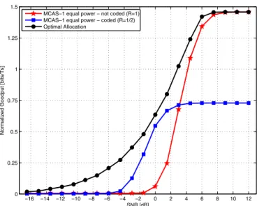
In Fig. 3 we show the average goodput over all sub-carriers and over different channel realizations as a function of the SNR. Clearly, the optimal allocation maximizes the goodput for all SNR conditions, outperforming the two equal power loading schemes. In the low SNR region, the optimal allocation charges the sub-carriers with the more robust coded MCAS-1, while in the high SNR region, the optimal solution is to use the more spectral efficient uncoded MCAS-1 in all sub-carriers.
B. Full multiplexing scenario
We consider the same scenario as in Section V-A. As in the previous case, the channel was assumed to be uncorrelated between antennas at both the transmitter and the receiver. In order to simplify the simulations, the channel was also as-sumed to be uncorrelated in the frequency domain. Moreover, as stated before, we have assumed that both the transmitter and the receiver have perfect knowledge of the channel matrix
1 4 8 12 16 20 24 28 32 0
1 2 3 4 5 6 7 8
Sub−carrier
SNR
instantaneous SNR mean SNR across sub−carriers
(a) Instantaneous SNR
1 4 8 12 16 20 24 28 32 0
0.25 0.5 0.75 1 1.25 1.5 1.75 2 2.25 2.5
Sub−carrier
Power [linear]
optimal power allocation equal power allocation
(b) Power Allocation
1 4 8 12 16 20 24 28 32 0
0.25 0.5 0.75 1 1.25 1.5 1.7
Sub−carrier
bits / Ts
optimal bit allocation equal bit allocation (coded) equal bit allocation (non−coded)
(c) Bit allocation
1 4 8 12 16 20 24 28 32 0
0.1 0.2 0.3 0.4 0.5 0.6 0.7 0.8 0.9 1
Sub−carrier
BLER
optimal allocation equal allocation (coded) equal allocation (non−coded)
(d) BLER performance
1 4 8 12 16 20 24 28 32 0
0.1 0.2 0.3 0.4 0.5 0.6 0.7 0.8 0.9 1 1.1 1.2 1.3 1.4 1.5
Sub−carrier
Normalized Goodput [bits/Ts]
optimal allocation equal allocation (coded) equal allocation (non−coded)
(e) Goodput performance
Fig. 2. Optimal AllocationvsEqual Power Allocation for SNR=0dB.
−16 −14 −12 −10 −8 −6 −4 −2 0 2 4 6 8 10 12 0
0.25 0.5 0.75 1 1.25 1.5
SNR [dB]
Normalized Goodput [bits/Ts]
MCAS−1 equal power − not coded (R=1) MCAS−1 equal power − coded (R=1/2) Optimal Allocation
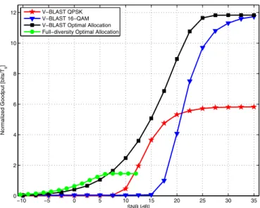
−10 −5 0 5 10 15 20 25 30 35 0
2 4 6 8 10 12
SNR [dB]
Normalized Goodput [bits/T
s
]
V−BLAST QPSK V−BLAST 16−QAM V−BLAST Optimal Allocation Full−diversity Optimal Allocation
Fig. 4. Normalized Goodput for 3Tx-3Rx as a function of SNR for the full-multiplexing scenario.
for each tone. We have considered two modulations, namely QPSK (or 4-QAM) and 16-QAM, and no coding.
In the following, we compare the performance of the V-BLAST with optimal allocation with that of V-V-BLAST with equal power loading using QPSK and equal power loading using 16-QAM. We have considered frames of 144 payload symbols, corresponding to the transmission of 48 symbols per antenna. This corresponds to a normalized goodput of 5.83 bits/Ts and 11.83 bits/Ts for QPSK and 16-QAM mod-ulation, respectively. In order to define the required SNR for
each modulation, we have considered a target BER of 10−2,
which gives us an SNR of 6.78 dB for QPSK and 13.50 dB for 16-QAM.
In Fig. 4 we show the average goodput over all sub-carriers and over different channel realizations as a function of the SNR. Clearly, the optimal allocation maximizes the goodput for all SNR conditions, outperforming the two equal power loading schemes. In the low SNR region, the optimal allocation charges the sub-carriers with the more robust QPSK modulation, while in the high SNR region, the optimal solution is to use the more spectral efficient 16-QAM modulation in all sub-carriers. We also show, in the same figure, the curve
for the full-diversity optimal allocation (first scenario). We can observe a small gain for SNR lower than 7 dB since the full-diversity schemes are able to profit from the channel diversity in this region to achieve a better SNR and better goodput. However, we believe that this can also be achieved by the V-BLAST scheme by the introduction of a coded QPSK modulation in the optimization process.
VI. CONCLUSIONS ANDPERSPECTIVES
We have presented an optimal power and bit allocation algorithm and shown how this optimal allocation can be applied to the MIMO-OFDM context, for the full-diversity and full-multiplexing scenarios. Simulation results show that the clever allocation of resources (power and MCAS) in accordance to the channel represents a great increase in the performance of the system in terms of goodput.
We are currently investigating the definition of the instan-taneous SNR for other MIMO schemes in order to define new MCAS to increase even more the goodput in the high SNR regime. As future steps, we will investigate more realistic channels. We will also study the issue of how the transmitter can have access to the instantaneous channel information and how the delay between the channel estimation and its use at the transmitter, as well as channel estimation errors, influences the performance of the system.
REFERENCES
[1] W. C. Freitas Jr., F. R. P. Cavalcanti, A. L. F. de Almeida, and R. Lopes, “Exploiting dimensions of the mimo wireless channel: multidimensional link adaptation,” inVehicular Technology Conference, 2005. VTC 2005-Spring. 2005 IEEE 61st, vol. 2, 30 May-1 June 2005, pp. 924 – 928. [2] T. Cover and J. Thomas,Elements of Information Theory. Wiley, 1991. [3] T. Starr, J. Cioffi, and P. Silverman, Understanding Digital Subscriber
Line Technology. Prentice Hall, 1998.
[4] V. Tarokh, H. Jafarkhani, and A. R. Calderbank, “Space-time Block Codes from Orthogonal Designs,” IEEE Transactions on Information Theory, vol. 5, pp. 1456–1467, July 1999.
[5] H. M. Carrasco, J. R. Fonollosa, and J. A. Delgado-Penin, “Performance Analysis of Space-Time Block Coding with Adaptive Modulation,” in
The 15th IEEE International Symposium on Personal, Indoor and Mobile Radio Communications (PIMRC 2004), Barcelona, Spain, September 2004.
[6] A. Milani, V. Tralli, and M. Zorzi, “On the Use of Rate and Power Adapta-tion in V-BLAST Systems for Data Protocol Performance Improvement,”