34
OPTIMAL STRUT-AND-TIE MODELS USING SMOOTH EVOLUTIONARY
STRUCTURAL OPTIMIZATION
MODELOS ÓTIMOS DE BELAS E TIRANTES USANDO OTMIZAÇÃO ESTRUTURAL EVOLUCIONÁRIA
Hélio Luiz Simonetti1; Valério Silva Almeida2; Luttgardes de Oliveira Neto3, Francisco de Assis das Neves4
1Master, Department of Civil Engineering, Federal University of Ouro Preto (UFOP), e-mail: heliosimonetti@ig.com.br 2Prof. Doctor, Department of Geotechnical and Structural Engineering from the School of Engineering of the University of
São Paulo (EPUSP), e-mail: valerio.almeida@pq.cnpq.br
3Prof. Doctor, Department of Civil Engineering, Faculty of Engineering (FE), (UNESP), e-mail: lutt@feb.unesp.br 4Prof. Doctor, Department of Civil Engineering, Federal University of Ouro Preto (UFOP), e-mail: fassis@em.ufop.br
RESUMO
O presente artigo apresenta um procedimento numérico para a obtenção de algumas configurações dos modelos clássicos de bielas e tirantes para certas aplicações estruturais. Para isso, faz-se o uso do método dos elementos finitos com o uso de uma formulação em teoria elasto-linear plana para a geração do elemento finito. Esse procedimento de análise é acoplado com um processo de otimização topológica denominado de SESO - Smoothing Evolutionary Structural Optimization. Esse método SESO baseia-se no procedimento de diminuição progressiva da contribuição de rigidez de elementos ineficientes com menores tensões até que ele não tenha mais influência, como se este estivesse em processo de danificação. São avaliados e comparados alguns exemplos de estruturas onde já se conhece a configuração ótima obtida dos modelos clássicos de bielas e tirantes, onde se demonstra a potencialidade da presente formulação para aplicações em estruturas genéricas.
Palavra-Chave: Estruturas em concreto armado, Modelo de bielas e tirantes, Otimização topológica, Método dos elementos finitos.
ABSTRACT
The present paper presents a numerical procedure for finding the optimal configuration of some strut and tie models to classical reinforced concrete structures. The Finite Element Method is formulated in plane stress state which is considered for the analysis in conjunction with a heuristic topological method called SESO - Smoothing Evolutionary Structural Optimization. The method SESO is based on the procedure of gradual reduction of stiffness contribution of the inefficient elements at lower stress until it no longer has influence, as if it were in the damage process. Optimal topologies of strut and tie models are presented in several instances with good settings which indicates good potentiality in using this procedure for generic application in reinforced concrete structure.
Keywords: Strut-and-tie model, Topology Optimization, Reinforced Concrete Structure, Finite Element Method
1 INTRODUCTION
35 computational ability to solve large problems using low-cost microprocessors, therefore creating an immense opportunity for research in applied mechanics.
As such, topological evaluation has been used in the field of mechanics to optimize structural components or elements in one, two, or three dimensions. To achieve this, stress and displacement analysis techniques, for example, by finite element (FEM) or boundary element methods (BEM), together with optimization criteria, such as Von Mises stress constraints, natural frequency or buckling, are used in searching of solutions by numerical-mathematical formulations.
Topology Optimization (TO) is a recent topic in the structural optimization field. However, the basic concepts that support the theoretical method have been established for over a century, as described by (ROZVANI,BENDSOE,KIRSCH,1995).The great advantage of TO, compared to traditional optimization methods, such as shape or parametric optimization, is that these methods are not able to change the layout of the original structure, failing to help the project conceptual framework for designing adequate flow stress.
In topological analysis, two methodologies are important: the micro and macro approaches. The micro approach considers the existence of a microporous media that depends on its geometry and the volumetric density of a unit cell representative of the material properties and its constitutive relations. An example for this group is the SIMP (Simple Isotropic material with penalization) method, (ROZVANY, BENDSØE, KIRSCH,1995) e (ROZVANY, ZHOU, BIRKER,1993).
In the macro approach, the topology of the structure is modified by the insertion of holes in the field. As an example of this group of TO, ESO (Evolutionary Structural Optimization) can be mentioned, which is based on the solution of the objective function when an element is removed from the finite element mesh and TSA (Topological Sensitivity Analysis), based on a scalar function, called topological derivative, which provides each set point in the problem domain the sensitivity of the cost function when a small hole is created, (SOKOLOWSKI,ZOCHOWSCKI,1999) e (NOVOTNY,FEIJÓO,PADRA,TARACO,2003). Strut-and-tie models are used to idealize the load transfer mechanism in a cracked structural concrete member at the ultimate limit states. The design task is mainly to identify the load transfer mechanism in a structural concrete member and reinforce the member such that this load path will safely transfer the applied loads to the supports. Obviously, some regions of a structural concrete member are not as effective in carrying loads as others. By eliminating these underutilized portions from a structural concrete member, the actual load transfer mechanism in the cracked concrete member can be found. The SESO technique is able to identify the underutilized portions of a structure and to remove them from the structure, to improve its performance.
Developing an appropriate strut- and- tie model, a structural concrete member can be transformed into a topology optimization problem of a continuum structure. The optimal topology of a plane stress continuum structure, using the SESO technique, tends towards a model of truss structures. Therefore, it is appropriate to apply this technology to the automatic generation of strut and tie models in concrete structures.
36 This paper presents the same theory described in (ALMEIDA, SIMONETTI, OLIVEIRA NETO, 2013) differing basically in the analyzed examples and in performance aspects of the optimized topologies.
To evaluate elasticity problems numerically, finite element analysis is applied, but instead using a plane–stress triangular finite element implemented with high-order modes for solving complex geometric problems. Three examples are presented to show this effect: (1) Deep beam with web openings; (2) Interior beam-column connections and (3) Bridge Pier.
2. SMOOTH EVOLUTIONARY STRUCTURAL OPTIMIZATION (SESO)
(XIE,STEVEN,1993), developed a very simple way to impose modifications on the topology of a structure, using a heuristic gradual removal of the mesh of the finite elements, corresponding to the regions that do not effectively contribute to a better performance of the structure. Therefore, in this paper, the parameters of interest for the optimization problem are evaluated in an iterative process in order to decrease the weight by employing the maximum stress criterion of the structure.
An initial finite element mesh is defined circumscribing the entire structure, or an extended domain of the design to include the boundary conditions (forces, displacements, cavities and other initial conditions).
Thus, the elastic problem is solved via FEM iteratively; the principal stress is evaluated at each element, the highest stress values are taken as reference and the finite element which presents stress values above the defined condition as described in inequality (1a) is removed:
,max
( )
vm vm
e RRk i
σ ≤ ⋅ σ (1a)
RRk+1=RRk+RE (1b)
where vm e
σ and ,max
vm i
σ are, respectively, the principal Von Mises stress of element in i-th
iteration and the maximum stress effective structure in iteration “i”; RR k is the Rejection Ratio at kth steady state (0.0 ≤ RR ≤ 1.0), which is an input datum that is updated using the
evolutionary rate (RE). The evolutionary process is defined by adding the rate of evolution (RE) to the RR factor, equation 1b, which is applied to control the removal process of the structure.
In the subsequent iteration, the elastic problem is solved again, without the finite elements be removed from the design body. The elimination of the rejected elements is observed to adopt Young´s modulus values or thickness in the order of initial values times 1.E-8. This procedure avoids a re-meshing approach of the body and a subsequent interference in the relative field of responses.
The same cycle of removing the elements used by inequality (1a) is repeated until there are no more elements that satisfy inequality (1a); when this occurs, or when the design volume is obtained, the steady state is reached. This procedure is known as hard kill and can be interpreted as follows:
0 if j ( )
0 if j
D
D j = ∈Γ
∈ Γ
37
where ( )D j is the constitutive matrix of element j∈Ω, D0 is the initial constitutive matrix,
Ω = Γ + Γ is the structure’s domain, {
(
e maxvm ( ))
} RR σ σΓ = Ω ≥ is the amount of elements that will not be removed from the structure (solid), and { /
(
vm maxvm ( ))
}e RR
σ σ
Γ = Ω − Γ = Ω Ω < is
the set of elements that are removed from the structure (empty parts), in i-th iteration, due to meeting inequality (1a).
(TANSKANEN,2002) proved mathematically that the ESO heuristic removal approach of these elements is associated to regions with low level of strain energy and it is a non-explicit minimization procedure in relation to their weight if compared to a deterministic method, such as the sequential linear programming (SLP) of the optimization algorithm technique.
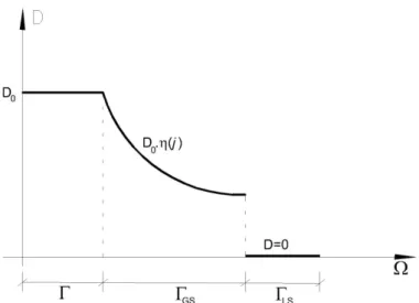
However, the removal of an element may unduly affect the optimum; one way to correct this deviation would be the possibility of reinserting the element in the structure. In this sense, a variant of the ESO stands out, the BESO - Bidirectional Evolutionary Structural Optimization, (QUERIN,1997). The SESO, Smooth ESO, comes from this mathematically consistent philosophy, weighting the Young’s Modulus (E) and making the strain energy of the element increases tending to the strain energy of the structure; then the gradient tends to zero and the direction of minimum is restored. This is a smooth heuristic of the withdrawal of finite elements of the ESO method. Thus, the elements that meet the inequality (1a) are divided into groups and organized in order of increasing stress. Then p% of those groups are excluded (elements with the least stress, ΓLSdomain) and (1-p%) is weighted by a regulatory function ( 0≤η( ) 1j ≤ ) and returned to the structure (ΓGSdomain). This removal and devolution procedure of elements is performed by a hyperbolic function, as shown in Figure 1, that weights the rate vm maxvm
e
σ σ within the Γdomain; that is, it permits the high-stress elements (closest to σmaxvm
but fulfilling the ESO constraint in the ΓGS domain) providing a better path for flow of tensions in each iteration.
The elements near the maximum limit stress are maintained in the structure, defining the procedure as a "non hard-kill" withdrawal, but a smooth process in the heuristic of elements removal. The soft kill procedure used in the SESO technique can be interpreted as follows:
0
i 0
D ( ) ( )
0 i
j GS
LS D if j
j D if j
if j η
∈Γ
= ⋅ Γ ∈Γ
∈Γ
(3)
where Γ=ΓLS +ΓGS, for 0≤
η
j( ) 1Γ ≤ . The function ηj(Γ) regulates the rate values max vm vm eσ σ
within the Γ domain and this procedure can eliminate the checkerboard problem.
The procedure proposed can be performed by using, for example, a constant function
( )
η Γ = Γ*EY(J), where EY is the Young’s Modulus of each element to be weighed, or a linear
function,
η
( )Γ =α
j+β
type. Because these two functions are continuous, they can be38 Figure 1. Smoothing of the volume of the elements removed in iteration i.
3. PERFORMANCE INDEX FOR THE SESO FORMULATION
The heuristic of the withdrawal of undesired elements by ESO/SESO methods is equivalent to the optimization procedure with weight function of structure (W) to find a minimum stationary point, as demonstrated by (TANSKANEN,2002). It is known that the design criteria are defined in technical standards for acceptable limits of stresses or strains and the problem consists on the minimization of the objective function in terms of weight, subject to an allowable stress constraint (σproject) which can be defined as:
NE e e 1 ,max
minimize W w ( )
subject to - 0 e vm project j t σ σ = = ≤
∑
(4)where Wis the total weight of the structure, we is the weight of the eth element, te is the
thickness of the eth element that is also treated as a design variable, ,max
σevm is the maximum von
Mises stress of each element in the structure and NE is the number of elements.
In (LIANG,XIE,STEVEN,1999) it is proposed that, instead of solving the optimization problem directly as previously indicated by equation (4), a monitoring parameter of the performance history, called performance index (PI), can be implemented for continuous structures with stress constraints, and this index is defined as:
0 i s s W PI W
= (5)
with: 0,max 0 0 σ ( ) vm s project W W σ = i,max σ ( ) vm s
i project i
W W
σ
=
(6a)
39
where W0 and Wi are the weights of initial and current design at ith iteration, σ0,max vm and
i,max
σ vm
are initial and ith-iteration maximum Von Mises stresses. Replacing equations (6a) and (6b) in (5) one obtains:
0,max 0 0,max 0 0 0,max 0
i,max i i,max i i,max i
vm vm vm
vm vm vm
i
W V V
PI
W V V
σ
σ
ρ
σ
σ
σ
ρ
σ
⋅
= ⋅ = ⋅ = ⋅ ⋅
(7)
where V0 and Vi are initial and ith-iteration volumes,
ρ
0 andρ
i are initial and ith-iterationdensities, which values are equal for an incompressible material. The smoothing generated due to Eq. (3) in terms of constitutive matrix can be written in terms of thickness due to the direct linear relation between them. In this context, the performance index in formula (7), which takes into account expression (3) in terms of each thickness and the regulating function from SESO procedure, is written as:
vm vm
0,max 0 0,max 0 0
vm vm
i,max i,max
1 1
σ . σ .
PI= . = .
σ NE . σ NE . . ( )
j j j j
j j
A t A t
A t A t
η
j= =
∑
∑
(8)where t0 is initial thickness and tj is thickness of jth element at ith iteration.
The optimal control is exerted by this performance index, because it is a "monitoring factor" in the region optimal design. The control of maximizing this parameter refers to the minimization of the control volume, since the ratio between the stresses does not change greatly, ranging around the unit value. Thus, the curve PI is characterized by the ratio of volumes and maximizing it means that its minimum volume has been found. However, if the index falls sharply, it is a strong indication that it underwent a local optimum or stationary configuration. There is also no guarantee that this is a global optimum, but an optimal configuration for engineering design.
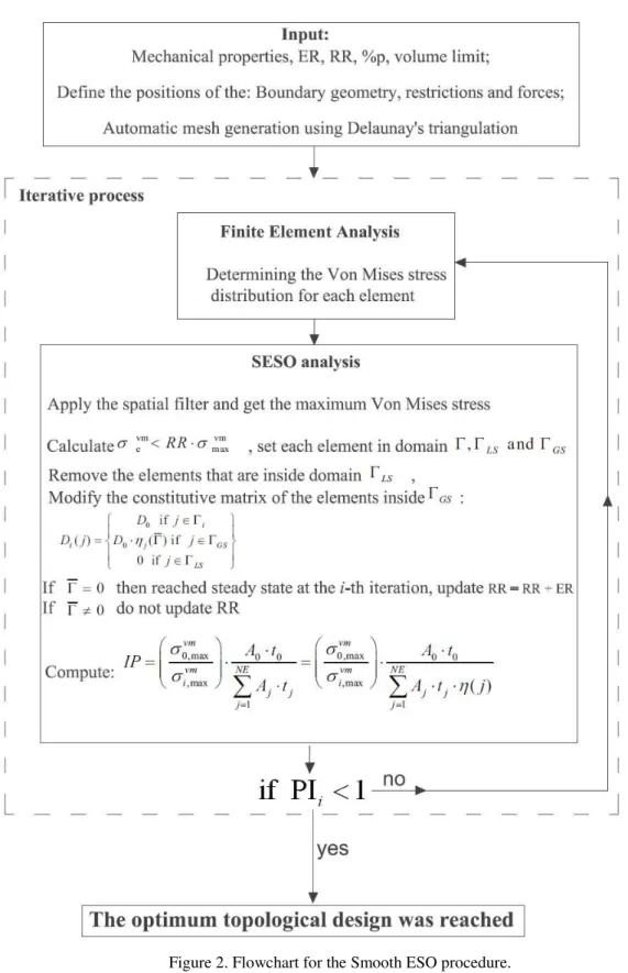
Finally, the algorithm of the evolutionary process can be described as follows or as in the flowchart indicated in Figure 2:
1. Discretize the domain for analysis with a refined mesh of finite elements;
2. Solve the linear elastic problem, applying displacement boundary conditions and external or body forces;
3. Determine the Von Mises stress distribution for each element and maximum at each iteration;
4. Divide the elements that violate eq. 1a, into n groups, where p% of n groups are deleted, and (1-p%) of n groups are returned to the structure, setting each element in domains
GS LS or Γ Γ
Γ, ;
5. Remove the elements that are inside domain ΓLS, and modify the constitutive matrix contributions related to elements inside ΓGSwith prescribed regulatory function;
6. If Γ=0, then the steady state is reached at ith iteration; then, update RR = RR + ER. If 0
≠
Γ , do not update RR;
7. While PIi > PIi-1 or Vi > Vfinal, (Vfinal is the prescribed volume) repeat steps 2 to 6; if PIi <<
40 Figure 2. Flowchart for the Smooth ESO procedure.
4. PROBLEMS ANALYZED
41
model, is usually employed. This analogy is shown by Ritter and Morsch at the beginning of twentieth century, associated with a reinforced concrete beam in an equivalent truss structure. The discrete elements (bars) represent the fields of tensile (rods) and compression (compressed struts) stress that emerge inside the structural element in bending effect. This analogy has been improved and it is still used by technical standards to design reinforced concrete beams in flexural and shear force and to define various criteria for determining safe limits in its procedures.
However, the application of this hypothesis for any structural element can lead to over or under sizing of certain parts of structures. This hypothesis is valid for parts of frames in which there is no interference from regions with high stress concentration, such as sections near the columns, cavities or other areas where the influence of strain due to shear is not negligible.
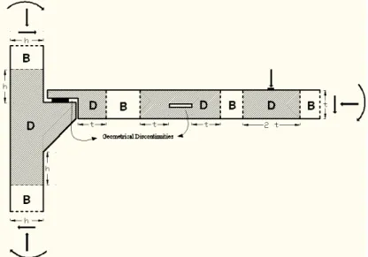
However, there are structural elements or regions where Bernoulli’s assumptions do not adequately represent the bending structural behavior and the stress distribution. Structural elements such as beams, walls, footings and foundation blocks, and special areas such as beam-column connection, openings in beams and geometric discontinuities, are examples, as shown in Figure 3. These regions, denominated “discontinuity regions D”, are limited to distances related to dimension order of structural adjacent elements (Saint Vernant’s Principle), in which shear stresses are applicable and the distribution of deformations in cross section is not linear.
Figure 3. Examples of D and B-regions in shaded and blanked areas.
The pioneering work by (SCHLAICH, SCHAFER, JENNEWEIN,1987)describes the strut-and-tie model more generally, covering equivalent truss models and including these regions and special structural elements.
42
in the centroid of each element, at each iteration process, using nodal stress values. Thus, some numerical examples are presented for evaluating and comparing the configurations obtained by classical models of strut-and-tie. The optimization parameters RR and RE, if not mentioned, are equal to 1% and defined as regulatory function ( ) 10 *4 ( )
EY j
η
Γ = − . The whole theory of SESO numerical technique is described by (ALMEIDA,SIMONETTI,OLIVEIRANETO,2013) e (SIMONETTI,ALMEIDA,OLIVEIRA NETO,2014).4.1 Deep beam with web openings
In this example, SESO was applied to find best topology for optimal structure and strut-and-tie models using triangular finite elements of high order, by comparing with the results presented in (LIANG,XIE,STEVEN,2000); the author used quadrilateral finite elements. The design domain and the boundary conditions are shown in Figure 4a; Figs. 4b, 4c, 4d e 4e show optimal settings obtained by (LIANG,XIE,STEVEN,2000). Young’s modulus of the material is30,088 MPa, Poisson's ratio is 0.15 and thickness is 100 mm. Two equal concentrated loads
of 140 kN are applied in the top of the beam. The procedure proposed can be performed by using, for example, a constant function ( ) 10 *4 ( )
EY j
η
Γ = − where EY is the Young’s Modulus of each element to be weighed, with the regulatory function 0≤η(j)≤1.43
Figures. 5a, 5b and 5c show the optimal topologies obtained by the present formulation, SESO, using refined mesh of 100x25 with a total triangular finite elements 4,688. The evolutionary procedure history presented in Figs. 5a, 5b and 5c was obtained with final volumes equal to 85,2%, 71,6% and 43,9%; the regions in red and blue respectively indicate the compressed (struts) and tensioned regions (ties). For the optimal settings shown in Figs. 5a and 5b, same optimization parameters (RR, rejection ratio and RE, evolutionary ratio) were used. The optimal configuration shown in Figure 5c was obtained with parameters RR equal to 1% and RE equal to 1% by volume at constant removed iteration equal 1.75 %. Note that the proposed algorithm is sensitive to the variation of these parameters, boundary conditions and the geometry of the element. Figure 5d shows the optimal strut-and-tie model.
Figure 5. History of topologies of beam structure obtained by the present model: (a) topology at iteration 40
(Vf =85.2%) (b) topology at iteration 80 (Vf =71.6%)c) Optimal Topology (Vf =43.9%), and d) Optimal
strut-and-tie model.
The graph in Figure 6 shows the monitoring made during the performance of the presente formulation to determine the optimal topology. The growth of the PI (performance index) values is plotted for each iteration, and the point at which PI drops sharply indicates that the previous iteration is thus the area of optimal design.
44 Figure 6. Optimization history.
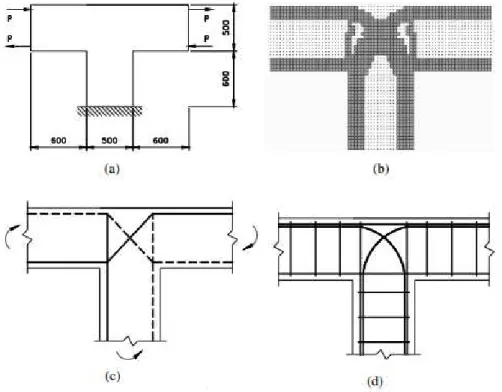
4.2 Interior beam-column connections
The design domain and the boundary conditions of the beam-column system are shown in Figure 7a. Under horizontal loads, one of the beams is subjected to positive moment and the other is subjected to negative one. Young’s Modulus is 28,567 MPa and Poisson ratio is 0.15.
This structure is modeled with a 68x108 refined mesh totaling 9024 triangular finite elements and the optimization procedure used parameters RE=0,5% and RR=1%. Volume removed by iteration is 5%. Figures 7b, 7c and 7d show optimal setting, the strut-and-tie model and reinforcement concrete, proposed by (LIANG,2005).
45
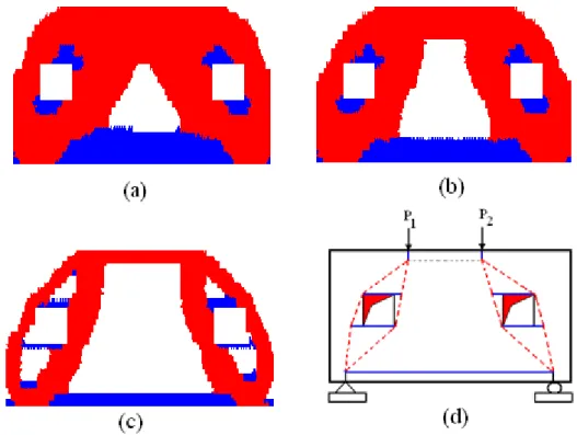
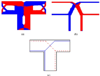
The method called PBO - Performance-Based Optimization was used. Figs. 8a and 8b show optimal topologies obtained by the present formulation, SESO, with final volumes equal to 82,6% and 27,7%; the regions in red and blue respectively indicate compressed (struts) and tensioned regions (ties). Fig 8c shows the strut-and-tie model.
Figure 8. History of topologies of beam structure obtained by the present model: (a) topology at iteration 60
(Vf =82.6%), (b) Optimal Topology (Vf =27.7%), and c) Optimal strut-and-tie model.
Figure 9 shows the flow of stress, respectively, in the first and the last iterations. The stress flow can be seen in the figure and the optimal setting for the strut-and-tie model is satisfactory and meets the conditions of the design.
Figure 9.Stress flow: a) iteration 1 and b) Iteration 290.
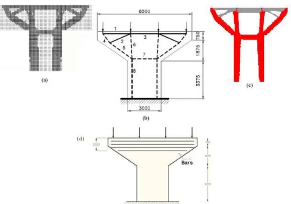
4.3 Bridge Pier
The bridge pier shown in Figure 10 is designed to support four concentrated loads of 2750 kN transferred from four steel-concrete composite girders. The bridge pier is clamped on the foundation. An initial thickness of 1500 mm is assumed for this bridge pier. Young’s Modulus is E= 28600 MPa and Poisson’s ratio is 0.15.
46
and Figure11b. Figure 11c shows optimal topology obtained by the present formulation, SESO, using a refined mesh 170x90, totaling 18,064 triangular finite elements, where the lighter areas represent ties. Table 1 shows the efforts obtained by (LIANG,STEVEN,2002) and by the present formulation for all the members shown in Figs. 11b and 11c. It shows a great similarity between the responses obtained by both procedures with same arrangement of bars originating from the strut-and-tie model as well as the efforts obtained at each member of the bridge pier, which can be designed and detailed following normative procedures.
Figure 11d shows the main horizontal reinforcement bars extended to the extremities in a range of 120 cm. Notes that the sum of the efforts in ties 1 and 2 is almost the same as that of tie 3. The vertical components of efforts in inclined ties are balanced by vertical reinforcement bars, as auxiliary reinforcements, which are not displayed in Figure 11d.
Figure 10 - Design domain of the structure, (LIANG,STEVEN,2002), measurements in mm.
Figure 11 – (a) Optimal topology (b) strut-and-tie model, proposed by (LIANG,STEVEN,2002), mm; (c) Optimal topology using the present model; (d) Proposed disposition of reinforcement for the present model
47 Table 1 – Strut and tie forces (kN) for each member of the bridge
Member Force
(LIANG,STEVEN,2002)
Force (present model)
1 2,114 2,192
2 1,162 1,195
3 3,363 3,454
4 -3,470 -3,589
5 -3,919 -4,083
6 -3,219 -3,482
7 -3,363 -3,569
8 -5,500 -5,964
5. CONCLUSIONS
Aiming to present a numerical formulation for the design of reinforced concrete structures under the focus of strut-and-tie model, a variant of topology optimization procedure, called Smooth Evolutionary Structural Optimization – SESO, was employed. The evolutionary procedure proposed, which smoothly removes the elements of discretized body, is coupled to a FEM formulation in plane stress state analysis. A priori, an extended initial domain is defined and, iteratively, the method seeks an optimal topology configuration in which natural members are set indicated by struts and ties. Thus, efforts in the members may be evaluated to enable the design of the reinforcements needed for each section. The formulation – SESO, in conjunction with a high order triangular finite element, presents robustness and efficiency to obtain optimal configurations. Three numerical examples demonstrated: a) good accuracy with strut-and-tie model configurations and the related effort values reported by other authors. The quantification and the disposition of reinforcements for a classic example described in international specific literature was also proposed;
b) another major improvement obtained by SESO formulation is the smoothing in classic TO problems, such as " checkerboard" in topology configurations of structures presented by cited authors in this article; c) finally, we emphasize that SESO is an evolutionary numerical technique which can be used in future researches in TO problems that include more complex phenomena such as nonlinearities and/or dynamic analysis problems mainly due to quality achieved, to optimal settings and also to low computational cost obtained in the problems presented that require intrinsically high computational cost.
ACKNOWLEDGEMENTS
48
6. REFERENCES
ALI M. Automatic generation of truss model for the optimal design of reinforced concrete structures. Dissertation. New York, United States of America, Cornell University, Ithaca; 1997.
ALMEIDA,V.S., SIMONETTI,H.L., OLIVEIRA NETO,L. Comparative analysis of strut-and-tie models using Smooth Evolutionary Structural Optimization, Engineering Structures, Vol. 56, p. 1665-1675,2013.
BENDSØE MP. Optimal Shape design as a material distribution problem. Structural Optimization 1989; 1: 193-202.
BERGAN PG, FELIPPA CA. A triangular membrane element with rotational degrees of freedom. Comp. Meths. in Appl. Mech. Eng. 1985; 50: 25-69.
BRUGGI M. Generating strut-and-tie patterns for reinforced concrete structures using topology optimization. Computers & Structures 2009; 87: 1483-1495.
BRUGGI M. On the automatic generation of strut and tie patterns under multiple load cases with application to the aseismic design of concrete structures. Adv Struct Eng 2010; 13(6): 1167–1181.
DUFF, I.S., REID JK. A set of Fortran subroutines for solving sparse symmetric sets of linear equations. Report R10533, AERE Harwell; 1982.
KWAR HG, NOH SH. Determination of strut-and-tie models using evolutionary structural optimization. Engineering Structures 2006; 28: 1440-1449.
LIANG QQ, STEVEN GP. A performance-based optimization method for topology design of continuum structures with mean compliance constraints. Computer Methods in Applied Mechanics and Engineering 2002; 191(13-14): 1471-1489.
LIANG QQ, Uy B, STEVEN GP. Performance-Based Optimization for Strut-Tie Modeling of Structural Concrete. Journal of Structural Engineering 2002; 190: 815–823.
LIANG QQ, XIE YM, Steven GP. Optimal topology selection of continuum structures with stress and displacement constraints. In. The Seventh East Asia-Pacific Conference on Structural Engineering & Construction. Kochi, Japan; 1999.
LIANG QQ, XIE YM, STEVEN GP. Topology optimization of strut-and-tie models in reinforced concrete structures using an evolutionary procedure. ACI Structural Journal 2000; 97(2): 322-330.
49
NOVOTNY AA, FEIJÓO RA, PADRA C, TARACO E. Topological Sensitivity Analysis. Computer Methods in Applied Mechanics and Engineering 2003; 192: 803-829.
QUERIN OM. Evolutionary Structural Optimization stress based formulation and implementation. Ph.D thesis. University of Sydney; 1997.
REINECK K-H. Shear and concrete tensile strength in the design concept of strut-and-tie models. Ibracon Structural Journal 2007; 3(1): 1-18.
ROZVANY GIN, BENDSØE MP, KIRSCH U. Layout optimization of structures. Applied Mechanics Review 1995; 48: 41-119.
ROZVANY GIN, ZHOU M, BIRKER T. Generalized shape optimization without homogenization. Structural Optimization 1992; 4: 250-252.
SCHLAICH J, SCHAFER K, Jennewein M. Toward a consistent design of structural concrete. PCI-Journal 1987; 32(3): 74 – 150.
SIMONETTI,H.L., ALMEIDA,V.S., OLIVEIRA NETO,L. A smooth evolutionary structural optimization procedure applied to plane stress problem, Engineering Structures, Vol. 75, p. 248-258, 2014.
SOKOLOWSKI J, ZOCHOWSKI A. On topological derivative in shape optimization. SIAM Journal of Control Optimization 1999; 37(4): 1251-1272.
TANSKANEN P. The evolutionary structural optimization method: theoretical aspects. Comput Methods Appl Mech Eng 2002; 191: 5485–5498.
VICTORIA M, QUERIN OM, MARTÍ P. Generation of strut-and-tie models by topology optimization using different material properties in tension and compression. Struct Multidisc Optim 2011; 44:247–258.