João Pedro Almodôvar Parada
Bachelor of Science in Materials EngineeringAdditive fabrication of electrically controlled
anepectic meshes
Dissertation submitted in partial fulfillment of the requirements for the degree of
Master of Science in Materials Engineering
Adviser: Prof. Dr. Alexandre Velhinho, Assistant Professor, Faculty of Sciences and Technology, NOVA University of Lisbon Co-adviser: Prof. Dr. João Paulo Borges, Associate Professor,
Faculty of Sciences and Technology, NOVA University of Lisbon
Examination Committee
Chairperson: Prof. Dr. João Pedro Botelho Veiga, Assistant Professor FCT-UNL Raporteur: Prof. Dr. Maria de Fátima Reis Vaz, Associate Professor IST-UL
Additive fabrication of electrically controlled anepectic meshes
Copyright © João Pedro Almodôvar Parada, Faculty of Sciences and Technology, NOVA University of Lisbon.
Acknowledgements
Como uma boa dissertação de mestrado torna-se difícil sem qualquer tipo de apoio, queria agradecer a todos aqueles me ajudaram ao longo deste percurso. Toda a ajuda oferecida foi indispensável para conseguir acabar este documento, além de todos os incentivos positivos que me deram força para continuar. Muito obrigado a todos.
Em primeiro lugar, gostaria de agradecer aos meus orientadores, Professor Doutor Alexandre Velhinho e Professor Doutor João Borges, por toda atenção disponibilizada, orientação e sobretudo paciência, não só neste período de tempo de escrita da dissertação, mas também ao longo dos meus 5 anos nesta instituição como aluno. Agradeço por esta oportunidade de trabalhar neste tema com a vossa orientação.
À Joana Raminhos, por me ter auxiliado em todo este percurso e em qualquer circunstância, desde dos meus primeiros desenhos até ao produto final. Sem dúvida, um dos alicerces deste trabalho.
Ao Professor Rui Igreja, por disponibilizar fontes de tensão e outros equipamentos necessários para o funcionamento dos testes elétricos. À Professora Isabel Ferreira, pela utilização e ajuda com equipamento de análise de infravermelho. Ao Jaime e Catarina, pela simpatia e disponibilidade com a camara térmica e montagem do circuito elétrico.
Ao Professor Rui Silva, pela sua boa disposição, conselhos e assistência com material no laboratório de metalurgia.
À toda a equipa do laboratórios de polímeros, em especial ao Professor João Canejo e Professora Paula Soares, pela utilização do espaço e alguns equipamentos indispensáveis. Aos meus colegas do curso de Engenharia de Materiais, por estarem sempre presentes nesta longa viagem e pela sua amizade verdadeira. Em especial, agradecer a um excelente grupo de amigos: Adriana, Rita, Joana, Beatriz, Sara, Tomás, Cezar, Hugo, David e João Duarte pela quantidade imensurável de tempo passado juntos que nunca irei esquecer. Também muito importante, agradecer à minha madrinha de praxe Carolina, por todos os pequenos gestos de encorajamento e ajuda no meu percurso académico. Espero que seja uma amizade que dure para sempre.
Aos meus amigos Pedro, Eduardo, César, Vasco e Joana, que foram a minha salvação quando precisava de relaxar e descontrair após horas de trabalho.
À minha amiga de infância Clara, a quem dedico todo este trabalho, por ter estado sempre ao meu lado mesmo nos piores momentos. Obrigado por todos os anos passados juntos.
A b s t r a c t
The present thesis documents the conceptual design and additive fabrication of composite anepectic meshes with incorporated wires that can induce a controlled temperature change through resistive heating by applying electric current. These anepectic meshes are characterized by having auxetic behaviour (negative Poisson’s ratio - NPR) in conjugation with a negative thermal expansion (NTE), composed of two distinct materials with none of the previous properties. Electrical tests took place with a hot plate beneath two glass plates, restraining the out-of-plane deformation of the sample, to carry out a preheating of the mesh, which was later considered essential to display anepectic behaviour. After electrical testing finished, image analysis was performed with the purpose of studying deformation in certain strategic points on the mesh to determine the coefficient of thermal expansion (CTE) at different temperatures. To evaluate heat dissipation and homogeneity, initial experiments were conducted alongside thermographic analysis. By adjusting wire positioning and including an extra power supply to the system, the heat dissipated from the heating element can be distributed more evenly throughout the entire mesh, which also enables a uniform deformation. Through optimized conditions and parameters, a peak CET value of −668 ×10−6 °C−1 was obtained for the regular scale mesh and −470 ×10−6 °C−1 for the smaller variant. Between the lowest and higher CET values, the highest difference was 500 for the regular scale mesh. Achieving a maximum electrical power (4A), this mesh was capable of deforming nearly 5% of its original form. Overall, the results of this thesis as a proof of concept confirms its feasibility and utility in biomedical applications where small and controlled deformation are necessary.
Keywords: Additive manufacturing, Auxetic materials, Negative thermal expansion, Anepectic, Resistive Heating, Tuneable thermal expansion
R e s u m o
A presente tese documenta o desenho conceptual e fabricação aditiva de malhas anepécticas compósitas com fios incorporados que conseguem induzir uma alteração controlada de temperatura através de um aquecimento resistivo ao aplicar corrente elétrica. Estas malhas anepécticas são caracterizadas por terem um comportamento auxético (coeficiente de Poisson negativo - NPR), em conjugação com uma expansão térmica negativa (NTE), composto por dois materiais distintos com nenhuma das propriedades anteriores. Testes elétricos realizaram-se com uma placa de aquecimento por baixo de duas placas de vidro com a amostra, limitando a deformação em Z na amostra, que mais tarde foi considerado essencial para apresentar comportamento anepéctico. Após os ensaios elétricos, análise de imagem foi realizada com a finalidade de estudar a deformação em certos pontos estratégicos na malha para determinar o coeficiente de expansão térmica (CET) a diferentes temperaturas. De modo a avaliar dissipação térmica e homogeneidade, ensaios iniciais foram realizados junto com uma análise termográfica. Ao ajustar o posicionamento do fio e adicionar uma fonte elétrica extra ao sistema, o calor dissipado do elemento de aquecimento pode ser distribuído uniformemente ao longo da malha inteira, o que também permite uma deformação uniforme. Através de condições e parâmetros otimizados, um valor máximo de −668 ×10−6 °C−1 foi alcançado para a malha com uma escala regular e −470 ×10−6 °C−1 para a variante mais pequena. Entre os valores de CET mínimo e máximo, a maior diferença foi de 500 para a malha com uma escala normal. Ao atingir um máximo de corrente elétrica (4A), esta malha foi capaz de deformar cerca de 5% da sua forma original. De modo geral, os resultados desta tese como uma prova de conceito confirma sua viabilidade e utilidade em aplicação biomédicas onde deformações pequenas e controladas são necessárias.
Palavras-chave: Fabricação aditiva, Materiais auxéticos, Expansão térmica negativa, Anepéctica, Aquecimento resistivo, Expansão térmica ajustável
C o nt e nt s
List of Figures xv
List of Tables xvii
List of Symbols xix
Acronyms xxi
1 Introduction 1
1.1 Metamaterials. . . 1
1.2 Auxetic Materials. . . 2
1.3 Anepectic Behaviour . . . 3
1.4 Electric Control and resistive heating. . . 3
2 Materials and Methods 7 2.1 Mesh Layout and wire placement . . . 7
2.2 Electrical testing and CET tuning . . . 8
2.3 Infrared Thermal Imaging . . . 8
3 Results and Discussion 9 3.1 Filament and wire characterization . . . 9
3.2 Infrared Thermography Analysis . . . 9
3.3 Coefficient of Thermal Expansion . . . 11
3.3.1 Mesh Preheating . . . 13
3.3.2 Power Supply and Wire Rearrangement . . . 14
3.3.3 Material and Wire Combination . . . 15
3.3.4 Mesh Scale and uniformity . . . 16
4 Conclusions and future perspectives 17
Bibliography 19
A Appendix 25
L i s t o f F i g u r e s
1.1 Causing mechanism of auxetic material for re-entrant geometries[30] . . . 2
1.2 2x2 and 3x3 mesh variations with a single wire . . . 4
2.1 Illustration of the montage utilized for electrical testing . . . 8
3.1 Heat propagation when utilizing two power supplies . . . 10
3.2 NPVA meshes before electrical testing . . . 11
3.3 Shrinkage variation at 80ºC , 100ºC and 120ºC respectively . . . 11
3.4 Temperature as a function of time in CET tuning of a 3x3 mesh . . . 12
3.5 Mesh layout with different wire placement . . . 14
A.1 Placement jig that keeps the wire extended while printing takes place . . . . 25
L i s t o f Ta b l e s
2.1 Overview of all the mesh combinations tested and not tested . . . 7
3.1 CET values in different preheating temperatures and combinations . . . 13
3.2 CET values corresponding to one or two power supplies . . . 14
3.3 Influence of two different materials on CET tuning . . . 15
3.4 Influence of mesh scale in tuning CET values . . . 16
L i s t o f S y mb o l s
α Coeficient of thermal expansion.
Ω Resistance.
∆l Change in length.
∆T Change in temperature.
lo Initial length .
Ac r o ny m s
2D Two dimensional.
2x2 Two by two.
3D Three dimensional.
3x3 Three by three.
CTE Coefficient of thermal expansion.
IR Infrared.
NPP Nylon and polypropylene.
NPR Negative Poisson’s ratio.
NPVA Nylon and polyvinyl alcohol.
NTE Negative thermal expansion.
PP Polypropylene.
PVA Polyvinyl alcohol.
SLS Selective laser sintering.
C h a p t e r
1
I nt r o d u c t i o n
1.1
Metamaterials
Metamaterials are artificial materials which physical properties manifest through adjusting its general architecture instead of composition. Such properties rarely appear spontaneously in nature [1]. Unlike convencional materials, metamaterials display a counterintuitive behavior by presenting unusual properties with negative value [2, 3]. Mechanical metamaterials, which have one or more unique mechanical properties associated with its design, can present negative Poisson’s ratio (auxetic), negative compressibility and negative stiffness [4,5].
These exceptional properties opened up several areas of interest such as in aerospace and military defence by providing improved indentation resistance and fracture toughness on protective equipment [5, 6]. Many 3D printed mechanical metamaterials composites were able to achieve high specific energy absorption when comparing to already studied metallic and composite structures while still being lighter [7–9]. In the biomedical and bioengineering areas, auxetic metamaterials are already being employed in numerous bioprostheses that benefit from these properties(e.g. annuloplasty prostheses, cushion pads and knee prosthetics) [10]. At a cellular level, exploration has been made in biological scaffolds by creating suspended web structures that exhibit positive and negative Poisson’s ratio [11] and hydrogels containing two different types of pores which size, shape and distribution can alter Poisson’s ratio from positive to negative at micro-scale. [12]
Multiple geometries were designed and analyzed in both 2D and 3D models. Some of the planar geometries already studied include triangular [13,14], chiral and anti-chiral [2, 15–17], star-shaped [13, 18], hexagonal [19] and other forms that combine reentrant geometries [14, 18]. In contrast with 2D geometries, most 3D structures are analyzed using the finite element method or other numerical simulations in order to test certain parameters without the need to produce a physical model [20, 21]. More complex structures similar to a buckliball form (refered to as bucklicrystals) [5] and some
C H A P T E R 1 . I N T RO D U C T I O N
To fabricate these detailed geometries, different manufacturing techniques have been employed mainly on 2D structures although most studies contemplate numerical methods or simulations such as the finite element method [20]. In particular, additive manufacturing techniques allow to reproduce these complex topological designs with extreme precision. A variety of lithography techniques [23,24], selective laser sintering (SLS) [7,25] and other assembly techniques [15,16] have been tested.
1.2
Auxetic Materials
Auxetic materials are materials that display negative Poisson’s ratio. With these mechanical property being inherent to the present architecture, auxetic materials are considered metamaterials. The term auxetic initially appeared through Evans which presented the mechanism as well as consequences to this behaviour and future applications [26]. However, Lakes was one of the first to mention materials with negative
Poisson’s ratio in his work with polyurethane foams [27].
The negative ratio between the tranverse strain and the longitudinal strain applied to a body or material defines the Poisson’s ratio: a dimensionless constant which depends on the direction of the applied force. For most materials, a longitudinal strain leads to the occurrence of transverse strains of opposite sign: e.g. a longitudinal elongation is accompanied by a transverse shrinkage. In isotropic materials, the Poisson’s ratio ranges between 0.25 and 0.33 [28]. Auxetic materials show the opposite behaviour: in the application of a longitudinal load, the material exhibits a lateral expansion. Figure 1.1 illustrates the mechanism for re-entrant star-shaped geometries which function similarly to other geometries that possess re-entrant corners [29].
Figure 1.1: Causing mechanism of auxetic material for re-entrant geometries[30]
As a result of the auxetic behaviour, these materials present other improved properties when comparing to conventional materials: resistance to indentation [31] and fracture [32], shear resistance [31], variable permeability [33] and the ability to create cellular structures with shape memory (shape memory auxetics). An antenna for space applications has already been designed with such structures [34]. For the manufacture of bulletproof vests or helmets, auxetic materials can absorb an incoming impact in a certain direction and distribute the force to other directions [6]. In biomedical applications, such as stents and artificial blood vessels, the mechanical expansion provided by the auxetic material enable a self-sustaining mechanism with no external control.
1 . 3 . A N E P E C T I C B E H AV I O U R
1.3
Anepectic Behaviour
For most solid materials, heating results in an increase in volume(constant pressure) which leads to a rise in temperature involving spacing of the interatomic bonds in the crystalline structure. Materials that have a negative thermal expansion coefficient exhibit the opposite behavior, they contract when heated [35]. With the purpose of obtaining this properties in metamaterials, a variety of composite mechanical metamaterials have been studied where the focus relies on two materials with different coefficients of thermal expansion but with dissimilar values [16,20,21,36]. It is possible to contract the composite, based on the position of the two materials in the chosen geometry. The mechanical response from the structure depends on the anisotropy of each material when subjected to different tensile or compressive loads [16].
In terms of applications, materials with negative thermal expansion are helpful when it is essential to keep the temperature range constant as well as their resulting deformation equal to zero. Such applications are associated with the dental field, sensors and microprocessors and other high precision mechanical devices [37].
The expression "Anepectic"was firstly attributed to the first non-virtual 3D printed mesh created with dual polymeric materials and designed by J.Raminhos et al [18]. These meshes combine a star-shaped re-entrant structure (which are auxetic as shown in figure 1.1) and dual materials with different coefficient of thermal expantion (CET).
As mentioned before, the positioning of each constituent in the star-shaped geometry results in the full structure exhibiting negative thermal expansion. According to the author [18], the present materials must also have identical stiffness, different CET and work above their respective Tg. When the conditions for anepectic behaviour are meet, it is
possible to tune several dimensional parameters, choose multiple materials and alter mesh scale to create the desired deformation. The meshes tested were submerged in silicone oil , which was heated with the assistance of a hot plate. By consecutive heating, different coefficent of thermal expantion values were obtained, resulting in permanent deformation.
1.4
Electric Control and resistive heating
The proposed design for anepectic meshes require a passive source of surrounding energy, making it harder to incorporate into biomedical devices. Most medical equipments, that correspond to these meshes - stents [38], surgical hernia meshes [39] and compression garments, lack the active component to control deformation through an on command setup. By introducing a heating element inside the mesh, it is hypothesised that not only the
C H A P T E R 1 . I N T RO D U C T I O N
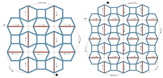
Without interfering with the mesh’s structural integrity, an array of conductive materials capable of inducing a controlled temperature change powered by an external power supply was implemented in the active components of the anepectic mesh. The conductive wire forms a complete circuit and passes across every red beam, as seen in figure 1.2.
During the priting process, the profile chosen changed to minimize material loss and prevent defects in the structure. For instance, by enabling the combing command, all nozzle travels stay within the area of the print. In conjunction with an increase of 1.5mm in Z-hop command, which controls the height of the nozzle after retracting, most of the material stays contained with minimal material loss in the surroundings. In all variations, there are thirteen layers with 0.06 mm in height which helped understand which layer number would be optimal to place the wire. For better printing adhesion, the printing bed’s temperature was raised to 100°C.
The printing starts normally and then stops at around 50% of the printing process. The red beams have a hollow center that is open to insert the heating element. With the wire fixed, the printing resumes normally with the printer covering and trapping the wire. As a consequence of the inherent complex geometry, the wire only passes through the red beams to simplify wire placement while printing.
The blue beams illustrate the material with the lower CTE and higher stiffness while the red beams the material with the highest CTE and lower stiffness. In conformity with J.Raminhos et al, both of these materials must have similar stiffness and differing CTE’s in addition to having the stiffer material(blue beams) shaping the re-entrant form and the more expansive material(red beams) between each star formation and limits.
Figure 1.2: 2x2 and 3x3 mesh variations with a single wire
1 . 4 . E L E C T R I C C O N T RO L A N D R E S I S T I V E H E AT I N G
A 3D printer with dual extruder was used to print all of the meshes, regardless of any change in parameters or conditions. Two main mesh scales were created: a smaller variant which contains only 4 unit cells and the original anepectic mesh which contains 9. All of the dimensions for both meshes were based on the Mesh #2 denominated by J.Raminhos [18].
The aim of this thesis is to achieve an alternative design to the already established anepectic mesh with the addition of an active control, which is made by changing electric current. Taking biomedical devices into account, coefficient of thermal expansion and shrinkage are to be optimize to ensure proper application in the area.
C h a p t e r
2
M a t e r i a l s a n d M e t h o d s
2.1
Mesh Layout and wire placement
In order to generate the complete design of the anepetic meshes with incorporated wires, the modeling software 123D Design was chosen. Two meshes were designed: a 2x2 and a 3x3 mesh. The unit cell have a star-shaped re-entrant geometry with inherent auxetic behavior. In this unit cell, each of the interior angles of the re-entrant star are 30° with the every beam having a width and thickness of 1 mm. Considering the geometrical symmetry, the distance between the middle of the red beam and the parallel blue beam is 10 mm whereas the distance between opposite red beams is 6.4 mm.
To encapsulate the wire, a squared centered hole of 0.5mm was created which passes along all of the red beams. In order to avoid any short circuit or heat dissipation in each intersection, a cone shaped separator was printed. Later on, these separators were replaced by a thin printed brim which was faster to obtain.
The meshes were printed with a commercialUltimaker 3™ fused filament dual printing-system which utilized the temperature profiles provided byUltimaker. Both of the meshes have thirteen layers with a filling density of 100% which were predetermined with the 3D cutting softwareUltimaker Cura. Between layer one to seven, the printing proceeds normally. When the eighth layer starts printing, the process stops so that a wire-placement jig that confines the wire can be placed on top of the printing to assist the wire’s placement and improve reproducibility. This support is presented in the Appendix. After resuming and completing the print, the support is taken off and can be reused for other prints. All of the combinations considered are presented in table 2.1. NPVA and NPP refer to the Nylon-PVA combination and Nylon-PP, respectively.
Table 2.1: Overview of all the mesh combinations tested and not tested
Power Supply Material Type 2x2 Copper Wire 2x2 Steel Wire 3x3 Copper Wire 3x3 Steel Wire NPVA X 7 X X
C H A P T E R 2 . M AT E R I A L S A N D M E T H O D S
With the intention of experimenting wires with different thermal conductivities and diameter, two types of wire were used: copper and steel wires that have 0.15mm and 0.3mm diameter respectively. All of these wires have the same length for each mesh scale and have a corresponding resistance of roughly 2 W.
2.2
Electrical testing and CET tuning
Before initiating electrical testing, red dots were made on the mesh in order to observe the deformation as the temperature changes. Movement from the mesh was captured with a digital SLR camera(Canon 1100D) that was set in a 90° angle to take photos consecutively in case of an sudden increment of temperature. When peak temperature was achieved, only one photograph/°C was taken. For monitoring the temperature during testing, a type K thermocouple located on one of the active beams measured the temperature while recorded by a data logger(Pico TC-08 USB). The mesh was positioned between two glass plates with the bottom one greased with oil to minimize motion hindrance effects due to friction, as seen in figure 2.1. A hot plate with controlled temperature was placed beneath the entire setup to initiate a preheating of the passive beams. Afterwards, electric current was applied to the outside wires that are isolated by the beams, initiating resistive heating.
CTE was calculated right after the increase of electric current when corresponding to certain specific temperatures rather than at stabilization point. Electric current was increased in spaced intervals considering the peak temperatures corresponding to each amperage.
Figure 2.1: Illustration of the montage utilized for electrical testing
2.3
Infrared Thermal Imaging
Throughout initial electrical testing, most of the deformation produced by the heating element did not affect the mesh uniformly. To understand how the induced heat affected the entire mesh, an infrared camera (FLIR SC305) was employed in conjunction with the setup shown in section 2.2 with the exception of the hot plate. This camera has a sensitivity of 0.05ºC at 30ºC with an object temperature range of -20°C to 120°C.
Infrared images were taken when the temperature stabilized. Likewise, temperatures of certain strategic points on the mesh were also taken with the appropriate temperature scale. It is also important to mention that these experiments took place on a closed environment to minimize heat dissipation and other disturbances.
C h a p t e r
3
R e s u l t s a n d D i s c u s s i o n
In this chapter, all stages of mesh characterization are discussed. In section 3.1, mesh combinations are presented and with the intention of comprehending the initial heat distribuition of the different mesh scales, section 3.2contains IR imaging when subjected to testing. Progression towards CET tuning, which is highlighted in section 3.3, starts by integrating an inicial preheating to the setup with different temperatures. Adding an extra power supply completes the final setup.
Afterwards, by altering material/wire combination as well as mesh scale and regarding all of the previous aspects, deformation controlled through adjusting electrical power can be achieved.
3.1
Filament and wire characterization
Each filament selected was supplied byUltimaker with no necessary changes in terms of its structure. Taking in consideration the mesh structure selected, the material chosen as the active beam is Nylon (polyamide; black) and the passive beams are PP (polypropylene; undyed) and PVA (polyvinyl alcohol; undyed). As a result, there are two
material combinations: Nylon-PVA and Nylon-PP.
All of these filaments’ important properties regarding this study namely Young’s modulus, glass transition temperature (Tg) and coefficient of thermal expansion of the
single material (CET), were obtained by J. Raminhos et al. [18]. These values are shown in table I.1 of the Annex.
3.2
Infrared Thermography Analysis
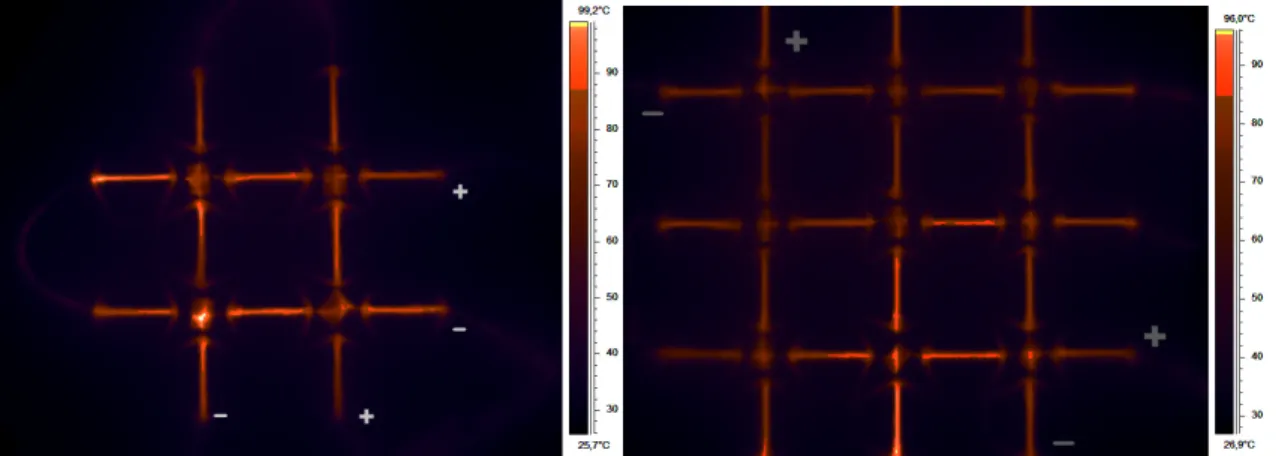
The thermographic analysis was conducted on the 2x2 and 3x3 meshes, as shown in figure 3.1. Both of them have the same material combination (NPVA) and wire (Copper). The white and grey plus(+) and minus(-) signs on figure3.1represent the eletrical terminals for the two power supplies utilized. Temperature was measured in the edge of each beam and at the intersection where the separator was placed. The average, minimum and
C H A P T E R 3 . R E S U LT S A N D D I S C U S S I O N
down corner in the intersection, possibly due to the separator having inadequate thickness to withstand the induced heat. Nearly half of the beams, especially when looking at the horizontal beams, are above the average temperature. It is possible that each wire has slightly different resistance, impairing induced heat. Printing process could also influence the insulation of the wire.
(a) 2x2 mesh IR image with 50% less light (b) 3x3 mesh IR image with 50% less light
Figure 3.1: Heat propagation when utilizing two power supplies
Considering the scale of the 3x3 mesh on image3.1(b), temperature distribution differ notably. Similar to the 2x2 mesh, temperature ranges from 61 to 94ºC with an average of 78ºC. In this particular case, only one of the unit cells appear to show temperatures above the average. This shows that the 3x3 mesh could be the choice when it comes to mesh scale, as deformation will take place evenly with few constraints.
However, assuming that temperature rises homogeneously on the mesh during electrical testing, some occasional and irregular deformation caused by printing could occur. This can cause CET values to shift based on a specific location. To minimize this effect, improving the automation when placing the conductive array and checking thoroughly if each layer prints properly, should remove these minor effects. Furthermore, in both meshes, the heat radiated from the beams fails to spread to the passive beams and to some areas on the edges of the active beams.
3 . 3 . C O E F F I C I E N T O F T H E R M A L E X PA N S I O N
3.3
Coefficient of Thermal Expansion
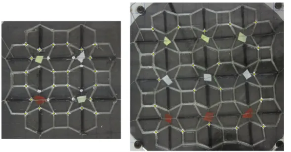
When measuring the overall value of CTE, total deformation from the mesh was taken into consideration. Figure3.2indicates the numerous initial points captured with the image processing software ImageJ which are represented by yellow dots. The values for CET (α)
Figure 3.2: NPVA meshes before electrical testing
corresponding to a certain temperature and deformation were calculated according with the equation3.1 :
α =∆l lo
× 1
∆T (3.1)
where ∆l is the change in length, lo is the initial length and ∆T change in temperature.
Shrinkage percentage was also calculated with the first term of equation 3.1, which is expressed as the ratio of change in length by initial length per point. Afterwards, an average was made with every CET value and shrinkage from the total fixed points. A sequential photo example can been seen in figure 3.3for the 2x2 variation.
C H A P T E R 3 . R E S U LT S A N D D I S C U S S I O N
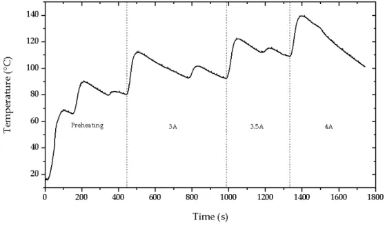
Regarding the temperature control procedure, figure 3.4 represents a time versus temperature graph example of a 3x3 mesh. For most meshes, the graph can be divided into four stages: preaheating, initial application of 3A, increase by 0.5A and ultimatly increase of 1A, for a final of 4A. Values higher than 4A appear to damage the wire and mesh structure (steel wire can reach around 4.5A).
On the initial stage, the objective is to reach the preheating temperature without forcing the mesh to deform. Due to the sensor being positioned on the bottom glass instead of the hot plate, temperature can deviate from the desired temperature. Nonetheless, electrical power would only be applied when temperature was stable.
As the current is applied, the mesh absorbs the induced heat and reaches the peak temperature quickly while deforming instantly. This temperature does not remain constant as the heat dissipation is higher than heat absorved.
Figure 3.4: Temperature as a function of time in CET tuning of a 3x3 mesh
3 . 3 . C O E F F I C I E N T O F T H E R M A L E X PA N S I O N
3.3.1 Mesh Preheating
As shown in section3.2, heating provided by electric current is insufficient to spread to the passive part of the mesh. In addition, prior mesh tests without a preheating have no deformation response and have a positive CET. It was hypothesized that in order to achieve anepectic behaviour, both passive and active beams must stay above the correspondent
Tg.
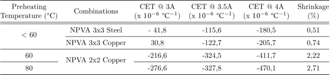
In table 3.1, different temperatures and mesh combinations were considered. It is important to note that when the preheating temperature goes above 80°C, the heating plate will by itself deform the mesh with no associated control. A temperature of 80°C ensured minimum deformation from the mesh caused by the hot plate.
Table 3.1: CET values in different preheating temperatures and combinations
Preheating Temperature (°C) Combinations CET @ 3A (x10−6°C−1) CET @ 3.5A (x10−6°C−1) CET @ 4A (x10−6°C−1) Shrinkage (%) < 60 NPVA 3x3 Steel - 41,8 -115,6 -180,5 0,51 NPVA 3x3 Copper 30,8 -122,7 -205,7 0,74 60 NPVA 2x2 Copper -216,6 -324,5 -411,7 2,22 80 -276,6 -327,8 -470,1 2,71
In conformity with data from table 3.1, temperatures below 60°C, with either wire, indicate a low shrinkage percentage. Although CET values are negative and anepetic behaviour is present, such low deformations are hardly noticeable. As temperature increases, shrinkage percentage increases as well. Looking at the Nylon-PVA 2x2 mesh with copper wire, at 4A, the CET is −470 × 10−6 °C−1 which significantly decreased compared with the others. Considering the CET range between 3A and 4A, it remains mostly equal (difference of 195) when comparing the same mesh tested with 60°C and 80°C. Increasing the temperature in this case only changes the minimum and maximum CET values correspondent to 3A and 4A, respectively.
This indicates that implementing a preheating to the initial setup completes the process and anepectic behavior can only be achieved with it. With electrical current constant, the CET range is influenced by the preheating temperature although the absolute difference remains approximately the same. While the minimum temperature for preheating was not determined, it is reasonable to say that it is close to Tg of both polymers.
C H A P T E R 3 . R E S U LT S A N D D I S C U S S I O N
3.3.2 Power Supply and Wire Rearrangement
Taking into account resistive heating, there are many nuances concerning dissipation. As long as there are resistive elements in a circuit, heat dissipation should be minimized whether it be with a good isolation for the conductor or changing material and circuit design altogether.
Initially, the mesh scructure was comprised of only one wire corresponding to one power supply. By making the wire pass through the mesh multiples times, heat dissipation would grow each time the wire passed to a different beam, resulting in a heterogeneous heat distribuition. This would cause different deformation in several distinct points on the mesh. In this sense, new scructures were created with two separate wires corresponding to two power supplies which are illustrated in figure 3.5 for each mesh scales. In each intersection, there is a thin separator that avoid any short circuit and conduction between the two wires.
Figure 3.5: Mesh layout with different wire placement
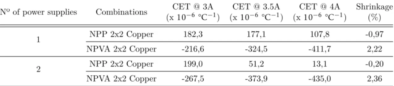
Table 3.2 presents the CTE values while changing the number of power supplies. Comparing the Nylon-PVA mesh, adding another power supply slightly lowered the CTE values and slightly increased shrinkage percentage. When the power supply was added, the range CET from 3A to 4A changed to an absolute 195 to 168, lowering the interval.
Although an additional power supply does not impact CET values heavily, on section 3.2 it is demostrated that this layout assists on the overall heat propagation. For that reason alone, CET values should be more consistent allowing the mesh to deform uniformly.
Table 3.2: CET values corresponding to one or two power supplies
Nº of power supplies Combinations CET @ 3A (x10−6°C−1) CET @ 3.5A (x10−6 °C−1) CET @ 4A (x10−6 °C−1) Shrinkage (%) 1 NPP 2x2 Copper 182,3 177,1 107,8 -0,97 NPVA 2x2 Copper -216,6 -324,5 -411,7 2,22 2 NPP 2x2 Copper 199,0 51,2 13,1 -0,20 NPVA 2x2 Copper -267,5 -373,9 -435,0 2,36 14
3 . 3 . C O E F F I C I E N T O F T H E R M A L E X PA N S I O N
3.3.3 Material and Wire Combination
With all of the filaments available, Nylon-PVA combination was adopted in accordance with J. Raminhoset al [18] which concluded that this combination minimized the CET values. It is also mentioned that a prerequisite for anepectic behavior consists on both materials having different thermal expansion but similar stiffness. This is necessary so that the material with lower CET imposes deformation on the other material which is more flexible but has a higher expansion. This implies that, as already stated, the material with lower CET should constitute the structural beams or passive beams and the material with higher CET the internal or active beams.
To better analyse this, Nylon-PP combination was also considered but with each material position inverted, which contradicts the reasoning on the previous paragraph. Given the flexibility of PP, the active nylon beam should, in theory, dilate enough to deform the structure, without concerning about PP expansion.
Several combinations were tested, each one with a different wire and mesh scale as shown in table3.3. All of these meshes were tested with two power supplies and preheating temperature of 80°C.
Table 3.3: Influence of two different materials on CET tuning
Material Combination Wire Type Mesh Scale CET @ 3A (x10−6 °C−1) CET @ 3.5A (x10−6 °C−1) CET @ 4A (x10−6 °C−1) Shrinkage (%) NPP Copper 2x2 199,0 51,2 13,1 -0,20 Steel 2x2 185,3 25,1 -21,9 0,12 3x3 45,7 34,8 12,9 -0,09 NPVA Copper 2x2 -276,6 -327,7 -470,1 2,71 3x3 -164,1 -403,9 -668,0 4,81 Steel 3x3 -14,1 -169,9 -233,6 0,98
By assessing the Nylon-PPA’s CET values in either wire or mesh scale, nearly each and every one are positive, excluding at 4A on the 2x2 mesh with steel wire. While this value is negative, it is near zero and deformation is barely noticeable. This reveals that Nylon-PP inverted combination may not lead to anepectic behaviour. With this in mind, comparing wire types over the Nylon-PP seems inconsistent.
Alternatively, Nylon-PVA meshes demonstrate significantly lower CET values. Looking at the 3x3 variations, it is possible to see a substantial drop at 4A. The CET range between
C H A P T E R 3 . R E S U LT S A N D D I S C U S S I O N
3.3.4 Mesh Scale and uniformity
Concerning primarily heat propagation, two different mesh scales were designed. The 2x2 mesh was created with the intention of maximizing heat efficiency which is inferior on a bigger scale mesh. However, the downside of this smaller scale can be seen when deformation takes place. The 3x3 scructure has nine repeating cells that include one in the center surrounded by the rest. This middle one retains deformation from the other cells and contracts more easily. When looking at the 2x2 structure, there are only four repetitive cells that in the center form a square. While this placement does not hinder deformation completely, it can be harder for deformation to take place globaly since the center part, in comparison to the 3x3 scale, lacks an auxetic element to it.
In table 3.4, CET and shrinkage values were obtained by just changing mesh scale, maintaining the usage of two power supplies and a preheating temperature of 80°C.
Table 3.4: Influence of mesh scale in tuning CET values
Combinations Mesh Scale CET @ 3A (x10−6°C−1) CET @ 3.5A (x10−6°C−1) CET @ 4A (x10−6 °C−1) Shrinkage (%) NPVA Copper Wire 2x2
-267,5 -327,7 -435,0 2,36 -270,7 -347,4 -455,7 2,55 -276,6 -373,9 -470,1 2,71 3x3 -164,1 -403,9 -668,0 4,81
In the interest of getting more reproducibility and consistent results from the meshes, many tests were made with the most interesting results shown in table 3.4. Several tests with the 2x2 meshes suggest an average shrinkage of 2.54% with a standard deviation of 0,143%. The CET ranges appear to be increasing linearly with shrinkage. With that being said, more tests should be made to verify the variance of this results.
Similarly, the 3x3 mesh presented one of the largest deformation with a shrinkage percentage of 4.81 % and maximum CET value of −668×10−6°C−1at 4A. This particular set of combinations also achieved the largest range between eletrical currents. As predicted before, the 3x3 mesh can deform more as a result of the central auxectic cell. Increasing the number of cells to test this variable can be made, although increasing it from 9 to 16 becomes quite complex when considering all of the possibilities regarding wire placement and heat propagation.
C h a p t e r
4
C o n c l u s i o n s a n d f u t u r e p e r s p e c t i ve s
The first relevant achievement as a proof of concept for this thesis is the integration of a conductive element in a 3D polymeric mesh, capable of inducing heat through resistive heating. Ceasing the 3D printing process halfway, the array of conductive materials was placed in middle of each beam that passes through, guaranteeing the confinement of the wire without compromising the mesh structure. Testing resulted in negative CET although it requires some prerequisites to fully function.
Besides the conditions regarding the mesh arrangement pointed by J.Raminhos et
al [18], the electrically controlled mesh requires a preheating that comprises the entire sample. The preheating temperature necessary to assist on testing should be at least above the Tg of both polymers. Nonetheless, this temperature must not exceed a value
where deformation originated by preheating takes place, since this disrupts the controlled deformation. While employing two power supplies and modifying the electric flow barely changed CET values, thermographic analysis revealed that the global mesh temperature became more uniform. In future designs, including a form of integrated insulation to the mesh would also help to distribute heat equally.
Regarding mesh scale, the 3x3 variation showed greater results in CET and shrinkage values when compared to the 2x2 mesh. Altering the mesh scale could improve this type of structure, although adding more unit cells and expanding the design might influence the ability to incorporate the wire consistently while printing. A future study should focus on changing the wire’s path in order to create localized deformation that can improve the anepectic behaviour demonstrated in these meshes. The NPVA combination proved to function accordingly to the already determined requirements for anepectic behaviour where NPP combination failed to, in spite of better flexibility.
Finally, an additional work to the current thesis could be including shape memory polymers(SMP), which can recover their original shape when subjected to a specific stimulus [40–42]. The metallic wire could work as the heating element to trigger the shape memory material and enhance the anepectic mesh by enabling partial or total
B i b l i o g r a p hy
[1] Y. Chen, Z. Jia, and L. Wang. “Hierarchical Honeycomb Lattice Metamaterials with Improved Thermal Resistance and Mechanical Properties”. In: Compos. Struct. (2016). i s s n: 0263-8223. d o i: 10.1016/j.compstruct.2016.05.048.
[2] Z. Li, R. Zhao, T. Koschny, M. Kafesaki, K. B. Alici, E. Colak, H. Caglayan, E. Ozbay, and C. M. Soukoulis. “Chiral metamaterials with negative refractive index based on four "u"split ring resonators”. In: Appl. Phys. Lett. 97.8 (2010), pp. 2010–2013. i s s n: 00036951. d o i: 10.1063/1.3457448.
[3] H. Jopek and T. Strk. “Thermoauxetic behavior of composite structures”. In:
Materials (Basel). 11.2 (2018). issn: 19961944. doi: 10.3390/ma11020294.
[4] Z. G. Nicolaou and A. E. Motter. “Mechanical metamaterials with negative compressibility transitions”. In: Nat. Mater. 11.7 (2012), pp. 608–613. issn: 14764660. d o i: 10.1038/nmat3331.
[5] C. Huang and L. Chen. “Negative Poisson’s Ratio in Modern Functional Materials”. In: Adv. Mater. (2016), pp. 8079–8096. issn: 15214095. doi: 10 . 1002 / adma . 201601363.
[6] M. Sanami, N. Ravirala, K. Alderson, and A. Alderson. “Auxetic materials for sports applications”. In: Procedia Eng. 72 (2014), pp. 453–458. issn: 18777058. d o i: 10.1016/j.proeng.2014.06.079.
[7] S. Yuan, F. Shen, J. Bai, C. K. Chua, J. Wei, and K. Zhou. “3D soft auxetic lattice structures fabricated by selective laser sintering: TPU powder evaluation and process optimization”. In: Mater. Des. 120 (2017), pp. 317–327. issn: 18734197. doi: 10.1016/j.matdes.2017.01.098.
[8] S. Yuan, C. K. Chua, and K. Zhou. “3D-Printed Mechanical Metamaterials with High Energy Absorption”. In: Adv. Mater. Technol. 4.3 (2019), pp. 1–9. issn: 2365709X. d o i: 10.1002/admt.201800419.
[9] E. B. Duoss, T. H. Weisgraber, K. Hearon, C. Zhu, W. Small IV, T. R. Metz, J. J. Vericella, H. D. Barth, J. D. Kuntz, R. S. Maxwell, C. M. Spadaccini, and T. S. Wilson. “Three-dimensional printing of elastomeric, cellular architectures with negative stiffness”. In: Adv. Funct. Mater. 24.31 (2014), pp. 4905–4913. issn: 16163028. d o i: 10.1002/adfm.201400451.
B I B L I O G R A P H Y
[12] Y. Ma, Y. Zheng, H. Meng, W. Song, X. Yao, and H. Lv. “Heterogeneous PVA hydrogels with micro-cells of both positive and negative Poisson’s ratios”. In: J.
Mech. Behav. Biomed. Mater. 23 (2013), pp. 22–31. issn: 17516161. doi: 10.
1016/j.jmbbm.2013.03.021.
[13] J. N. Grima, R. Gatt, B. Ellul, and E. Chetcuti. “Auxetic behaviour in non-crystalline materials having star or triangular shaped perforations”. In: J. Non. Cryst. Solids 356.37-40 (2010), pp. 1980–1987. i s s n: 00223093. d o i: 10.1016/j.jnoncrysol. 2010.05.074.
[14] C. K. Ng, K. K. Saxena, R. Das, and E. I. Saavedra Flores. “On the anisotropic and negative thermal expansion from dual-material re-entrant-type cellular metamaterials”. In: J. Mater. Sci. 52.2 (2017), pp. 899–912. issn: 15734803. doi: 10.1007/s10853-016-0385-7.
[15] H. Ebrahimi, D. Mousanezhad, H. Nayeb-Hashemi, J. Norato, and A. Vaziri. “3D cellular metamaterials with planar anti-chiral topology”. In: Mater. Des. 145.2017 (2018), pp. 226–231. i s s n: 18734197. d o i: 10.1016/j.matdes.2018.02.052. [16] C. S. Ha, E. Hestekin, J. Li, M. E. Plesha, and R. S. Lakes. “Controllable thermal
expansion of large magnitude in chiral negative Poisson’s ratio lattices”. In: Phys.
Status Solidi Basic Res. 252.7 (2015), pp. 1431–1434. issn: 15213951. doi: 10. 1002/pssb.201552158.
[17] T. Li, X. Hu, Y. Chen, and L. Wang. “Harnessing out-of-plane deformation to design 3D architected lattice metamaterials with tunable Poisson’s ratio”. In: Sci. Rep. 7.1 (2017), pp. 1–10. i s s n: 20452322. d o i: 10.1038/s41598-017-09218-w.
[18] J. S. Raminhos, J. P. Borges, and A. Velhinho. “Development of polymeric anepectic meshes: Auxetic metamaterials with negative thermal expansion”. In: Smart Mater.
Struct. 28.4 (2019). issn: 1361665X. doi: 10.1088/1361-665X/ab034b.
[19] L. Mizzi, D. Attard, A. Casha, J. N. Grima, and R. Gatt. “On the suitability of hexagonal honeycombs as stent geometries”. In: Phys. Status Solidi Basic Res. 251.2 (2014), pp. 328–337. i s s n: 03701972. d o i: 10.1002/pssb.201384255. [20] L. Ai and X. L. Gao. “Three-dimensional metamaterials with a negative Poisson’s
ratio and a non-positive coefficient of thermal expansion”. In: Int. J. Mech.
Sci. 135.December 2017 (2018), pp. 101–113. issn: 00207403. doi: 10.1016/j.
ijmecsci.2017.10.042.
[21] Y. Li, Y. Chen, T. Li, S. Cao, and L. Wang. “Hoberman-sphere-inspired lattice metamaterials with tunable negative thermal expansion”. In: Compos. Struct. 189.January (2018), pp. 586–597. i s s n: 02638223. d o i: 10.1016/j.compstruct. 2018.01.108.
B I B L I O G R A P H Y
[22] K. Wang, Y. H. Chang, Y. W. Chen, C. Zhang, and B. Wang. “Designable dual-material auxetic metadual-materials using three-dimensional printing”. In: Mater. Des. 67 (2015), pp. 159–164. i s s n: 18734197. d o i: 10.1016/j.matdes.2014.11.033. [23] J. J. Warner, A. R. Gillies, H. H. Hwang, H. Zhang, R. L. Lieber, and S. Chen.
“3D-printed biomaterials with regional auxetic properties”. In: J. Mech. Behav.
Biomed. Mater. 76.March (2017), pp. 145–152. issn: 18780180. doi: 10.1016/j.
jmbbm.2017.05.016.
[24] J. Qu, M. Kadic, A. Naber, and M. Wegener. “Micro-Structured Two-Component 3D Metamaterials with Negative Thermal-Expansion Coefficient from Positive Constituents”. In: Sci. Rep. 7.December 2016 (2017), pp. 1–8. issn: 20452322. d o i: 10.1038/srep40643.
[25] J. Xiong, D. Gu, H. Chen, D. Dai, and Q. Shi. “Structural optimization of re-entrant negative Poisson’s ratio structure fabricated by selective laser melting”. In: Mater.
Des. 120 (2017), pp. 307–316. issn: 18734197. doi: 10.1016/j.matdes.2017.02.
022.
[26] K. E. Evans. “Auxetic polymers: a new range of materials”. In: Endeavour 15.4 (1991), pp. 170–174. i s s n: 01609327. d o i: 10.1016/0160-9327(91)90123-S. [27] R. Lakes. “Foam structures with a negative poisson’s ratio”. In: Science (80-. ).
235.4792 (1987), pp. 1038–1040. i s s n: 00368075. d o i: 10.1126/science.235. 4792.1038.
[28] G. N. Greaves, A. L. Greer, R. S. Lakes, and T. Rouxel. “Erratum: Poisson’s ratio and modern materials (Nature Materials (2011) 10 (823837))”. In: Nat. Mater. 10.12 (2011), p. 986. i s s n: 14761122. d o i: 10.1038/nmat3177.
[29] P. S. Theocaris, G. E. Stavroulakis, and P. D. Panagiotopoulos. “Negative Poisson’s ratios in composites with star-shaped inclusions: A numerical homogenization approach”. In: Arch. Appl. Mech. 67.4 (1997), pp. 274–286. issn: 09391533. d o i: 10.1007/s004190050117.
[30] S Alvermann. Effective Viscoelastic Behaviour of Celular Auxetic Materials. Vol. Ph.D. 2008. i s b n: 9783902465924.
[31] D. Photiou, N. Prastiti, E. Sarris, and G. Constantinides. “On the conical indentation response of elastic auxetic materials: Effects of Poisson’s ratio, contact friction and cone angle”. In: Int. J. Solids Struct. 81 (2016), pp. 33–42. issn: 00207683. doi: 10.1016/j.ijsolstr.2015.10.020.
B I B L I O G R A P H Y
[33] J. H. Oh, Y. E. Kwon, H. J. Lee, and Y. Y. Kim. “Elastic metamaterials for independent realization of negativity in density and stiffness”. In: Sci. Rep. 6.January (2016), pp. 1–10. i s s n: 20452322. d o i: 10.1038/srep23630.
[34] S. Jacobs, C. Coconnier, D. Dimaio, F. Scarpa, M. Toso, and J. Martinez. “Deployable auxetic shape memory alloy cellular antenna demonstrator: Design, manufacturing and modal testing”. In: Smart Mater. Struct. 21.7 (2012). issn: 09641726. d o i: 10.1088/0964-1726/21/7/075013.
[35] K. Takenaka. “Negative thermal expansion materials: Technological key for control of thermal expansion”. In: Sci. Technol. Adv. Mater. 13.1 (2012). issn: 14686996. d o i: 10.1088/1468-6996/13/1/013001.
[36] D. Li, J. Ma, L. Dong, and R. S. Lakes. “A bi-material structure with Poisson’s ratio tunable from positive to negative via temperature control”. In: Mater. Lett. 181 (2016), pp. 285–288. i s s n: 18734979. d o i: 10.1016/j.matlet.2016.06.054. [37] W. Miller, D. S. Mackenzie, C. W. Smith, and K. E. Evans. “A generalised scale-independent mechanism for tailoring of thermal expansivity: Positive and negative”.
In: Mech. Mater. 40.4-5 (2008), pp. 351–361. issn: 01676636. doi: 10.1016/j.
mechmat.2007.09.004.
[38] M. Najabat, A. James, and I. U. Rehman. “Auxetic oesophageal stents : structure and mechanical properties”. In: (2014), pp. 527–553. d o i: 10.1007/s10856-013-5067-2.
[39] D. H. Ballard, U. Jammalamadaka, K. Tappa, J. A. Weisman, C. J. Boyer, J. S. Alexander, and P. K. Woodard. “3D printing of surgical hernia meshes impregnated with contrast agents: in vitro proof of concept with imaging characteristics on computed tomography”. In: 3D Print. Med. 4.1 (2018). doi: 10.1186/s41205-018-0037-4.
[40] F. Pilate, A. Toncheva, P. Dubois, and J. M. Raquez. “Shape-memory polymers for multiple applications in the materials world”. In: Eur. Polym. J. 80 (2016), pp. 268–294. i s s n: 00143057. d o i: 10.1016/j.eurpolymj.2016.05.004.
[41] K. Yu, A. Ritchie, Y. Mao, M. L. Dunn, and H. J. Qi. “Controlled Sequential Shape Changing Components by 3D Printing of Shape Memory Polymer Multimaterials”.
In: Procedia IUTAM 12 (2015), pp. 193–203. issn: 22109838. doi: 10.1016/j.
piutam.2014.12.021.
[42] Q. Zhao, H. J. Qi, and T. Xie. “Recent progress in shape memory polymer: New behavior, enabling materials, and mechanistic understanding”. In: Prog. Polym.
Sci. 49-50 (2015), pp. 79–120. issn: 00796700. doi: 10.1016/j.progpolymsci.
2015.04.001.
B I B L I O G R A P H Y
[43] Y. Yang, Y. Chen, Y. Wei, and Y. Li. “3D printing of shape memory polymer for functional part fabrication”. In: Int. J. Adv. Manuf. Technol. 84.9-12 (2016), pp. 2079–2095. i s s n: 14333015. d o i: 10.1007/s00170-015-7843-2.
A p p e n d i x
A
A p p e n d i x
Figure A.1: Placement jig that keeps the wire extended while printing takes place
(a) 2x2 NPVA mesh (b) 3x3 NPVA mesh
A
n
n
e
x
I
A n n e x
Table I.1: Material properties for Nylon, PP and PVA(obtained from J. Raminhos) [18]
Material Young’s modulus (GPa) CTE(x 10−6 °C−1) Tg (°C)
Nylon 0.889 166 35
PP 0.152 248 -25
![Figure 1.1: Causing mechanism of auxetic material for re-entrant geometries[30]](https://thumb-eu.123doks.com/thumbv2/123dok_br/18158794.872665/24.892.152.721.730.881/figure-causing-mechanism-auxetic-material-entrant-geometries.webp)