ISSN :0976-6812
VOLUME
2
NUMBER
2
Jl!JLY-DECEMBER
2011
A Multi-nodal Ring Finite Eleinent for Analysis of Pipe Deflection
E .M.M. Fonseca1
, FJ.M.Q. de Melo2 and M .L.R. Madureir a3
1 Deparcmenc of Applied Mechanics, Campus de Sca. Apolonia Ap. 1134, Polycechnic lnscicuce of Braganca,
5301-857, Braganca, Portugal, E-mail: efonseca@ipb.pe
2Deparcmenc of Mechanical Engineering, Universicy of Aveiro, 3810-193, Aveiro, Portugal
3Deparcmenc of Mechanical Engineering, Faculcy of Engineering of Universicy of Porco, 4200-465 Porco, Portugal
Abstract: The main objective of this work is to present a numerical formulation to solve the problem of the deformation analysis
of thin-walled circular cylindrical pipes under concentrated loads. The solution is based on a displacement jield entirely defined from a set of trigonometric functions where the amplitudes are assigned as nodal parameters in a multi-nodal jinite element. With this formulation it is possible to provide an easy altemative too! when cbmpared with a complex jinite shell ar solid element modelling for the sarne type of applications. The present work pernzits to examine the deflection of pipe rings subjected to lateral (transverse) static loading conditions. Severa! case studies presented have been compared and discussed with numerical analyses results obtained with a shell element from A nsys® programme.
Keywords: multi-nodal ring; pipe; deflection; trigonometric functions.
1. INTRODUC'flON
Piping structures have high technological importance in different fields of applications, as fluid transport, energy production and chemical processes. Advanced structural applications, as nuclear power production, aeronautics and aerospace industry, must withstand high stress leveis and extreme temperature environment, this demanding exigent safety design standard and skilful inspection steps for certification of fitness for the purpose of these types of structures. These piping elements exhibit complex deformations fields giveri their toroidal geometry and the multiplicity of the configuration of externa! loads. The perfonnance of piping structures in its abjlity to support load is typically assessed by the measure of deflection from its initial shape. This characteristic controls the design limitation on flexible structures and helps to identify structural problems associated with other performance criteria.
The study of the flexibility and stress state of piping structures subjected to generalized forces has been an area of interest of many engineers and physicists, given the high inter.est of the theme in many structural applications. Important innovative contributions for this research was registered by Theodore von Karman [ 1 ], who proposed the first really effective solution-based on a Fourier expansion displacement field and a variational method. Vigness [2] generalized the solution and proposed an experimental procedure to verify the derived bending
*
Corresponding Author: efonseca@ipb.ptequations.
G.
Thomson [3] worked with an analytical formulation using doubly-defined trigonometric series functions to deve1op the displacement field and performed many experimental studies. Óry and Wilc:iek[4] presented an economical method based on transfer matrix techniques to define the stress and strain calculation. The technique of expanding the displacement and load field trigonometric functions has been followed unti1 the emergence and continuous development of finite elements. The use of trigonometric functions combined with the current algebraic shape functions used in the development offinite elements, in the approach to the solution of problems in structural mechanics has known encouraging contributions [ 4, 5]. News models used for stress and displacements fields determination, under mechanical or thermal loads, were formulated using numerical techniques with new finite elements [6-12]. Studies on circular cylindrical shells under concentrated forces have been presented by many researchers using curved beam, shell and solid [13, 14]. The particular case ofthe formulation of cylindrical shells using ring elements has a straightforward contribution from Ofiate [ 15], where this author used a combined formulation for the displacement field dealing with Fourier series along the circumference and algebraic shape functions alongthe axial direction. Karamanos [16] investigated the instability caused by pressure for the two and three dimensional tube under two opposite concentrated radial loads using a nonlinear tini te element tools and experimental validation. The study ofthe effect ofradial Ioads on cylindrical shells has an important role in the engineering design andE.M.M. Fonseca, FJM. Q. de Melo and M.L.R. Madureira
installation conditions of pressure vessels, having cylindrical shape. Furthermore the response of o ii and gas pipelines undertransverse load conditions, caused by trawl gears or anchors is also important due the possible catastrophic damage [ 17], as well as, lateral impact loading on tubular members of offshore platforms. Relevant literature reveals that investigations increased on the study of deformation oftubular sections dueto concentrated and uniformly distributed lateral or transverse loads [16-19].
The aim of this study is to develop an alternative numerical method for pipe ring analysis when used in buried sewerage piping or when submitted to mechanical loads generated during the transportation to the plant site or during the installation procedures. The present work extends the alternative formulation, based on a multi-nodal ring finite element with two nodal sections, used to simulate concentrated loads in the referred situations, previous presented and experimentally validated by Fonseca [11]. ln this work, severa! numerical results obtained by ring element will be compared with other shell element from Ansys® programme. The studied cases permits to examine the deflection of pipe rings subjected to transverse static loads. The multi-nodal ring element presents a good accuracy for the displacement field under general ized loads in different structural applications. The displacement calculation at any transverse section is easy, given the simplicity of the i.wolved algorithms in the fonnulation. The main advantage is associated to the generation of simple meshes with low number of elements, remarkable economy in degrees offreedom and in computational time.
2. A MULTI-NODAL RING FINITE ELEMENT FORMULATION
The basic kinematics assumptions refer to the deformation of a thin shell as used in a small-defection analysis, as referred in [11]. The assumptions in the problem fonnulation of in-plane bending are: The shell is thin, this meaning that the normal to the shell surface does not distort and the transverse section is inextensible, not including pressure effects. The strain analysis and curvature geometry field of a non-symmetrically deformed cylindrical shell may be founded on the behaviour of plates and shells of revolution. Kinematics expressions relating the midsurface strains are expressed by ( 1-3) and the curvatures and twist by (4-5).
1 (
av
Ci2w)
X = -
- - + -
andee r2
ae ae"
where ê.1·s is the longitudinal membrane strain, êH6 is the meridional curvature from ovalization,
y,
6 the shear strain,Xee is the meridional curvature variation from ovalization and
x,6
the twist variation.A simplified theory is useful under certain conditions and
is applicable to a variety of shells fonns. However, we shall deal only with the inextensional deformation of circular cylindrical shells. This theory is often preferred when shell structures resist loading principally through bending action. Such cases include a cylinder subjected to loads without axial symrnetry and confined to a small circumferential portion and there is considerable bending caused by changes in curvature, but no stretching ofmidsurface length. Defonnations ofthese types are thus described as inextensional referred in (20]. ln this shell theory, the midsurface in-plane strain components given by equations ( 1-3) are taken to be zero. We real is e from equation (1) that (u) depends on 8 and equation (2) Jeads to:
w
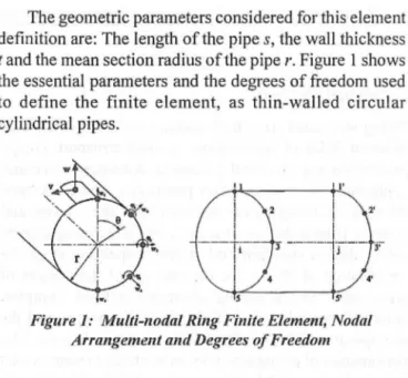
= - Civ I Ci8 ( 6)The geometric parameters considered for this element definition are: The length ofthe pipes, the wall thickness
t and the mean section radius ofthe pipe r. Figure I shows the essential parameters and the degrees of freedom used to define the finite element, as thin-walled circular cylindrical pipes.
Figure 1: Multi-nodal Ring Finite Element, Nodal Arrangement and Degrees of Freedom
The displacement field proposed characterises a uniform ovalization in the section and a variation along the shell length. To obtain the shape functions a displacement field has been considered in the normal and radial direction.
As represented in figure 1 the element present tive nodes under symmetric conditions and a total of eight degrees of freedom per ring section. Consequently, only a half of a ring section is needed to consider when trigono-metric even functions are used. The initial radial displacement used to define the ovalization effect must be calcdated using the trigonometric polynomial approxi-mation. A formulation based on trigonometric functions is used and eight parameters are necessary to define the transversal displacement field approximated by equation 7.
A Mulli-nodal Ring Finite Elem ent for Analysis of Pipe D eflection
9 9
w(s' e)=
2>i-l
i cos ie+
s~)i-li
sin i e (7)i=2 i= 2
Using simple differential equation from beam bending theory the transverse displacement can be calculated:
9 9
w(s' e)=-
LA-!
sin ie-s
LA-!
cos i e (8)i=2
The rotation field is considered using the derivative function ofthe transverse displacement field:
( e) 1
àw
.
If
·2 • ·e Sf
b ·2 ·e<p s, = - - = --.L..J a;_1 z sm z - - "'-' i-I z cos z
r
ae
r i=2 r i=2(9)
The unknown parameters a; and b; are determined by
imposing boundary conditions according to the ring element section i and j considered, resulting a system of equations to be solved.
The degrees of freedom considered in the proposed multi-nodal ring element are: Node I and 5 are the transversal . displacement and their derivatives vanish, for nodes 2 at 4
have a radial displacement and one derivative function. A system with 16 equations is solved for i and j section
of the ring element and shapes functions are obtained: ' (10) with
{õf
= { w;; Wz; <l'z; w;; <l'Ji W4i <1'4;~;
w;J WzJ<p21 W31 <p31 W41 <p 41 W51
r
which {õ} represents the global displacement field for transversal and rotation degrees offreedom in the sem i nodal ring and [ B'] is constant matrixthat results from the imposed boundary conditions. For node 1 the transversal displacement is equal to one and ali others equal to zero. The first shape function appears and is called Nli. With imposed equation (6) we determine the shape function BNli. The sarne has been used for ali others nodes. The unknown constants {a;} are determined inverting the system equation ( 1 0). The first shape function is represented by the equation (11 ). With these conditions, a new shape functions are determined and the generic local displacements field for in-plane finite element formu1ation are given by equations (12) and (13).
[ 3 5 1 3 1 9 1 7 ]
N1 = -cos(2e)
+
-cos(3e)+
-cos( 4e)+
-cos(5e)+
___:.cos(6e)+
-cos(7e)+
-cos(8e)+
cos(9e)-I 16 12 8 3 2 16 64 8 64 (11)
[ 3 cos(2e) 5 cos(3e) 1 cos(4e) 3 cos(5e) 1 cos(6e) 9 cos(7e) 1 cos(8e) 7 cos(9e)]
-s
+
+
+
. +
+
+
+
16
L
32L
8L
32L
16L
64L
8L
64L
v(s, e)= BN,;w;;
+
BN2;W2;+
BN;;<!>2;+
BN3;w;;+
BN;;<p 3;+
BN4;+
BN;;Cfi,4;+
BN5;Ws;+
+BN,1w;1
+
BN21W21+
BN~1
<p21
+
BN31 w;1+
BN{1<p31+
BN41w_,
1+
BN;1<p41+
BN51
~1
(12)
w(s, e)= N,;w;;
+
Nz;Wz;+
N;;<l'z;+
N3iw;i+
N;;<l'J;+
N4iW4i+
N;i<p4i+
Ns;~;+
+
N, 1w;1+
N2}V;_
1+
N~1
<p21
+
N31w;1+
N{1<p31+
N 41W41+
N;1<p41+
N 51W51(13)
Ali other shape functions are determined in the sarne form. This formulation presents a simple formula for calculation ofthe displacement field forthe tangential (v) and transversal (w) displacement under a shell element:
{v
wf
=[N]x{õ} (14) As referred pfeviously, the mechanical deformation model considers that the pipe undergoes a semi-membrane strain field by the equations ( 1-5).The typical use ofthe principie ofvirtual work Ieads to the system ofalgebraic equations. Having solved the system of algebraic equations, the _ displacement field is obtained for ali the nodes of the multi-nodal ring finite element.
3. PIPE RING ANALYSIS DUE CONCENTRATED LOADS
Concentrated Ioads can cause a pipe deflection, with bending o r twisting ofthe pipe surface. This is an important
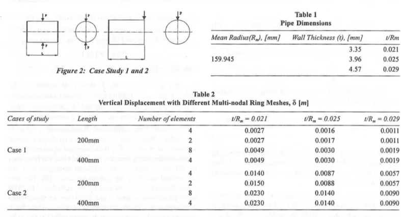
item included in the engineering design procedures. The problem presented here, refers to a ring structure with rigid ends, subjected to concentrated Ioad, figure 2. The Ioad is equal (P = 1000 kN) and it is applied at the middle (case I)
or at the end ofthe pipe length (case 2).
The material is assumed to be isotropic. For material properties the elastic modulus was taken (E= 200GPa),
Poisson's ratio (v = 0.3) and yield stress (
aY
= 560MPa).Different geometric configurations are considered in ali pipe rings studied and defmed in table 1. For each one two different Iengths were considered (L= 200, 400 mm). ln this study the ring flexibility in ali cases is equal to Dmlt ~ 95.
A total of 24 numerical simulations were obtained using the multi-nodal ring finite element represented in figure I for different studied cases. Table 2 represent the results ofthe vertical displacement using different meshes for multi-nodal ring element. This finite element performs well even in the coarse mes~ configurations.
E.M.M. Fonseca, FJM.Q. de Melo and M.L.R. Madureira
-§-
$--§-
4
Figure 2: Case Study I and 2
Table 1 Pipe Dimensions
Mean Radius(R,J, {mm} Wall Thickness (t), [mm}
3.35
I59.945 3.96
4.57
t/Rm
0.02I O.Ó25 0.029
Table 2
Vertical Displacement with Different Multi-nodal Ring Meshes, õ [m]
Cases of study Length Number of elements
4
200mm 2
Case I 8
400mm 4
4
200mm 2
Case 2 8
400mm 4
Also of 12 numerical simulations are presented using Ansys®, and a finite Shell 63 element was used, with 4 nodes and 6 degrees offreedom per each node: translations in the x, y, and z nodal directions and rotations. The deformed shapes are linear in both in-plane directions. Whenever applicable, boundary conditions for symmetry were used due the shell geometry and the load system. Different meshes were used in Ansys® programme, 16 and 32 elements when pipe length is equal to 200 or 400mm,
t/Rnr = 0.021 t/Rm = 0.025 t/Rm = 0.029
0.0027 O.OOI6 O.OOII 0.0027 O.OOI7 O.OOil 0.0049 0.0030 O.OOI9 0.0049 0.0030 O.OOI9 O.OI40 0.0087 0.0057 O.OI50 0.0088 0.0057 0.0230 O.OI40 0.0090 0.0230 O.OI40 0.0090
respectively. With multi-nodal ring, 4 and 8 elements were used for the same conditions. The maximum displacement obtained with the multi-nodal ring element and shell element for each study case is represented in table 3.
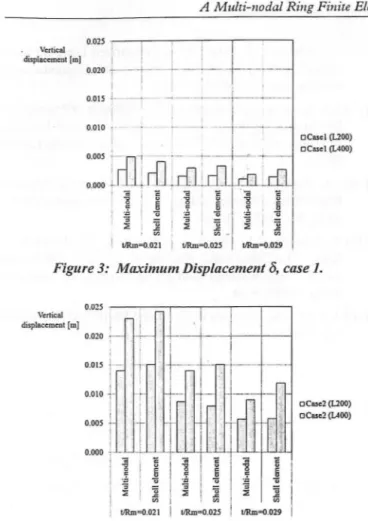
ln ali studied cases the results agree when shell thickness is thin or moderated. Figure 3 and figure 4 represent the comparison ofthe maximum vertical displacement between the multi-nodal ring and shell element.
Table 3
Comparison ofVertical Displacement, õ [m]
Cases of study Length t/Rnr = 0.02] Multi-nodal Shell
200mm 0.0027 0.002I Case I 400mm 0.0049 0.004I 200mm O.OI40 O.OI5I Case 2 400mm 0.0230 0.0242
ln ali simulations the vertical displacement are larger when the pipe length increases. Case 2 refers to a ring pipe solution with more deflection. The ring deflection is smailer in ali simulations, when the pipe thickness increases. The comparison between multi-nodal ring element and shell element from the finite element code gave similar results. Figure 5 shows the response of ali studied cases and considering clifferent lengths, using normalized values for applied load (p} and obtained displacement (x).
t/Rm = 0.025 1/Rm = 0.029 Multi-nodal Shell Multi-nOdal Shell
0.0016 O.OOI7 O.OOII O.OOI5 0.0030 0.0034 O.OOI9 0.0028 0.0087 0.0079 0.0057 0.0058 O.OI40 O.OI51 0.0090 O.OII9
The applied load value P is normalized using the
following equation:
(p =pI P.) (15)
The vertical displacement 8 is normalized with respect to the ring pipe radius R'" (Y = 8 I R,,). ·
A Mulli- nodal Ring Finile Elem entfor Analysis of Pipe Deflecrion
0.025 r -- . - - - , - - - - . - - , - - - ,
Vertical
I
displacemcnt [m)
!
I
0.020 +-, --+, _ __,___
I i
0. 015
i---i
0.010 i
I O Case I (L200)
o Case I (L400)
Figure 3: M aximum Displacement 8, case 1.
Vc:rtical
displacement [ m] 1 0.020 :---0.015
j-· __
,_
I
l
I .
0.010
r
l
0.005!
l
OCI13e2 (L200) 8Case2 (L400)
Q.
-d '
g 60 ~
..J
Lo
i
ê
oz 40 -1
30 '
0.000 ·;
-I
tl
~I
::I
II t!Rm =0.021 I t!Rm:0.029
Figure 4: Mll?'imum Displacement 8, case 2.
0.05 0.075 O. I 0.125 0.15 0.175
Nom1alized displacement, Y
-+-Casei , L=200 -o-Case I ,'L=400 - • Case2, L=200 -o-Case2, L=400
Figure 5: Normalized Load and Displacement, Case 1 and Case 2.
The behaviour of ali paths is similar, studied load case 2 reaches greater values of deflection when compared with load case 1. Also, when increased length and decreasing the ratio between thickness and radius, the pipe deflection is higher.
4. CONCLUSION
The presented formulation using a multi-nodal ring element under symmetric conditions makes possible to determine a displacement fiefd under shell surface for in-plane
bending in thin-walled cylindrical pipes. The multi-nodal ring element exhibits excellent behaviour in linear bending conditions like shell elements. The numerical results to validate-the accuracy ofthe multi-nodal ring element have shown a good agreement when compared with similar analysis using Ansys® . The presented solution has performed well even with coarse element meshes, and appears as a simple and easy-to-handle altemative to the use of shell elements. ln studied cases the vertical displacement are larger when the pipe length incr~ases and the ring deflection is smaller when the pipe thickness increases.
References
[1] Th. von Kárman, "Über Di e Formanderung Dunnwaindiger Rohre Insbesondere Federnder Ausgleichrohre", Zeits V.D.I., Band 55, 1911, ss. 889-1895.
[2] I. Vigness, "Elastic Properties of Curved Tubes", ASME, 65, (1943) 105-120. '
[3] G. Thomson, "The Influence of End Constraints on Pipe
Bends, PhD Thesis, University ofStrathclyde, Scotland, UK, 1980.
[4] H. Óry, E. Wilczek, "Stress and Stiffness Calculation of Thin-walled Curved Pipes with Realistic Boundary Conditions Being Loaded in the Plane of Curvature", International Journal of Pressure Vessels and Piping, 12, (1983) 167-189.
[5] H. Ohtsubo, O. Watanabe, "Stress Analysis of Pipe Bends by Ring Elements", Journal of Pressure Vesssel Technology, 100, (1978) 112-121.
[6] K.J. Bathe, C.A. Almeida, "A Simple and Effective Pipe Elbow Element-Pressure Stiffening Effects", Journal of Applied Mechanics, 49, (I 982) 914-916.
[7] F.J.M.Q. Melo, P.M.S.T. Castro, "A Reduced Integration Mindlin Beam Element for Linear Elastic Stress Analysis of Curved Pipes Under Generalized ln-plane Loading", Computers & Structures, 43(4), (1992) 787-794.
[8] E.M.M. Fonseca, F.J .M.Q . Melo, C.A.M : Oliveira; "Determination ofFiexibility Factors on Curved Pipes with End Restraints Using a Semi-analytic Formulation", International Journal of Pressure Vessels and Piping, 79(12), (2002) 829-840.
[9] E.M.M. Fonseca, F.J.M.Q. Melo, C.A.M. Oliveira, "The Thermal and Mechanical Behaviour of Structural Steel Piping Systems", Jnternational Journal of Pressure Vessels and Piping, 82(2), (2005) 145-153 .
[10] E.M.M. Fonseca, F.J.M.Q. Melo , C.A .M. Oliveira, "Numerical Analysis ofPiping Elbows for ln-plane Bending and Internal Pressure", Thin-Walled Structures, 44, 2006 393-398.
[11] E.M .M. Fonseca, F.J.M.Q. Melo, C.A .M. Oliveira, "Trigonometric Function used to Formulate a Multi-nodal Finite Tubular Element", Journal Mechanics Research Communications, 34, 2006 54-62.
E.M.M. Fonseca, RJM. Q. de Melo and M.L.R. Madureira
[12] E.M.M. Fonseca, F.J.M.Q. Melo, "Numerical Analysis of Curved Pipes Submitted to ln-plane Loading Conditions",
Thin-Walled Structures, 48, (20 1 O) 103-109.
[13] R. Kouhia, R. Stenberg, "A Simple LinearNonconforming Shell Element", IASS-IACM 2000, Fourth International Col!oquium on Computational of Shell Spatial Structures,
2000, Greece.
[14] A. Gobetti, R . Nascimbene, " Elasto-plastic, Nonlinear Analysis of a Locking-free Shear!flexible Curved Beam Element", ECCM-European Conference on Computational
Mechanics, 2001, Poland.
[15] E. Oiiate, Cálculo de Estructuras por el Método de Elementos Finitos (in spanish, Structure Calculation using the Finite Element Method), CIMNE Edition, The Polythecnic University ofCalaunia, 1992, chapts 10, a2 and 14.
[16] S.A. Karamanos, "Stability of Pressurized Long ~nelastic
Cylinders Under Radial Transverse Loads", Computational
M~18, (1996) 444-453.
[17] S.A. Karamanos, C. Eleftheriadis, "Collapse ofPressurized Elastopastic Tubular Members Under Lateral Loads",
Jnternational Journal of Mechanical Sciences, 46, (2004)
35-56.
[18] J.A. DeRuntz, P.G. Hodge, "Crushing of a Tube Between Rigid Plates", Journal of Applied Mechanics, Trans. ASrVfE,
85/E, 30 (1963) 391-395.
[19] W. John~on, S.K. Ghosh, A.G. Mamalis, T.Y. Reddy, S.R. Reid, "The Quasi-Static Piercing of Cylindrical Tubes or Shells", Jnternational Journal of Mechanical Sciences,
22(1): (1980).9-20.
[20] A.C. Ugural, "Stresses in Plates and Shells", McGraw-Hill Inc, 1981.