This content has been downloaded from IOPscience. Please scroll down to see the full text.
Download details:
IP Address: 164.41.72.83
This content was downloaded on 01/08/2017 at 12:55
Please note that terms and conditions apply.
View the table of contents for this issue, or go to the journal homepage for more
A Permanent Magnet Hall Thruster for Pulsed Orbit
Control of Lunar Polar Satellites.
Brunno Silva Moraes1
, Jos´e Leonardo Ferreira1
, Ivan Soares Ferreira1 Othon Cabo Winter2, D´ecio Cardozo Mour˜ao2
1 - Institute of Physics. University of Bras´ılia – UnB, CEP 70919-970, Bras´ılia – DF – Brazil 2 - S˜ao Paulo State University – UNESP, Av. Ariberto Pereira da Cunha, 333, CP 205, CEP 12516-410, Guaratinguet´a - SP - Brazil
E-mail: [email protected]
Abstract.
Future Moon missions devoted to Lunar surface remote sensing, for example, will require very fine and accurate orbit control. It is well known that Lunar satellites in polar orbits will suffer a high increase on the eccentricity due to the gravitational perturbation of the Earth. Without proper orbit correction the satellite lifetime will decrease and end up in a collision with the Moon surface. It is pointed out by many authors that this effect is a natural consequence of the Lidov-Kozai resonance. We studied different arcs of active lunar satellite propulsion, centered on the orbit apoapsis or periapsis, in order to be able to introduce a correction of the eccentricity at each cycle. The proposed method is based on an approach intended to keep the orbital eccentricity of the satellite at low values.
1. Introduction
Recently, the ESA’s Small Mission for Advanced Research in Technology (SMART-1) completes the mission of scanning the Lunar surface from its own orbit. It was the first spacecraft which achieved the Moon’s orbit employing plasma rockets (for details, see e.g., [1]), and therefore become a very successful start of an epoch of Moon exploration using plasma technology.
Certainly, in few years it will be build several Lunar bases, mainly in the near poles region, where the probability to found water reservoirs is larger. Because of that, the need of reconnaissance satellites in polar orbits is increasing. However, high inclination orbits around the Moon are susceptible to the Lidov-Kozai resonance [2], which will limit the satellite lifetime by increasing the orbit eccentricity, until the collision between Moon’s surface and the satellite. At the Lidov-Kozai resonance scenario, eccentricity and inclination of a small object’s orbit are coupled according third Delaunay momentum, therefore a perturbation would have no influence on semi-major axis. Those quantities could undergo changes and, for high inclined orbits, the eccentricity will grow without control[9].
Winter et al (2009) [3] proposed, in a previous work, a method to increase the lifetime of polar lunar satellites in near circular orbit using low thrust propulsion and the locally optimal thrust. This approach is suitable considering a costly attitude control and missions in which large fluctuations of radial distance are acceptable.
In the present paper, we studied the employment of permanent magnets Hall-effect thrust to introduce a correction of the eccentricity at each cycle of lunar orbit, and therefore sustain very
low values to the eccentricity of the orbit. In the next section we describe these thruster, and after that we describe the simulation methods and we show and comment our results.
2. Hall-effect plasma thrusters
Hall-effect plasma thrusters are now a very good option for space probes primary propulsion and also for station keeping of medium and large satellites. This is because of their high specific impulse and thrust efficiencies, which is related to an economy in terms of propellant mass utilization and satellite lifetime. First Hall thrusters were developed in mid 1950’s, and they were also called Closed Drift Thrusters, as become clear that the closed electron drift current inside the source channel, promoted by the crossed electric (axial) and magnetic (radial) fields configurations, is responsible for the acceleration of the plasma beam (for a historical review, see [4]). Instead of a good comprehension of the acceleration mechanism and the steady state plasma dynamics, today a lot of problems on the role of electrons transport and plasma fluctuations and instabilities still open (e.g. [5]).
Figure 1. Permanent Magnet Hall-effect Plasma thruster design showing its main components. The external shields are omitted for clarity.
Figure 2. Calculated thrust as function of input power for some values of thruster efficiency.
Figure 3. Calculated mass flux, as function of power, to a constant thrust of 100 mN, for several values of thruster efficiency.
Typically, well developed Hall thrusters shows a total efficiency between 50 and 60 %, for a maximum specific impulse of 2500 s ([6]). One limiting factor in the account for a larger total efficiency is electric efficiency, which is the amount of input power that is actually used to accelerate the beam. For an ordinary Hall thruster, this efficiency also includes the power needed to generate the magnetic field. Looking on this aspect, the Permanent Magnets Hall Thruster (PMHT) was originally proposed [7]. In PMHT, an array of permanent magnets, carefully designed and placed both beside the inner and outer walls, generates the magnetic field. This solution should be responsible for a increase of the total efficiency of the next generation of
thrusters. We can see in Figure 1 the permanent magnets Hall-effect thruster schematics. And in Figures 2 and 3 is plotted the calculated thrust and the calculated mass flux, respectively, both as function of input power and for different efficiencies. Those values will be used as input for the orbit control simulations.
Currently, there are several ongoing studies in order to understand the dynamics of the plasma in the PMHT interior and exterior (plume regions). The main issue is the presence of all three magnetic field components in relevant intensity inside the channel and near the external wall of the plasma source [7]. This is very different from what is regularly found in Hall thrusters, i.e., a mainly radial magnetic field, present only in the plasma acceleration channel exit. Despite of that, the use of the PMHT in space missions, including deep space maneuvering, is already underway, as for an example in the work by Santos et. al. (2008)[8].
3. Method
To perform the numerical simulations, has been considered the 3-Body problem: Moon, Earth and satellite. In that case, the coordinate system was chosen to be centered in the Earth-Moon barycenter and the equations of motion of the satellite are given by:
¨ ~ x = 2 X i=1
G mi
|x~i−~x|
3 (x~i−~x) (1)
¨ ~ y = 2 X i=1
G mi
|y~i−~y|
3 (y~i−~y) (2)
¨ ~z =
2
X
i=1
G mi
|z~i−~z|
3(z~i−~z) (3)
In this system, the Earth’s motion is described by:
¨ ~ xi =
2
X
j=1,j6=i
G mi
|x~j −x~i|
3(x~j−x~i) (4)
¨ ~ yi =
2
X
j=1,j6=i
G mi
|y~j−y~i|
3 (y~j−y~i) (5)
¨ ~ zi =
2
X
j=1,j6=i
G mi
|z~j−z~i|
3 (z~j−z~i) (6)
Wherem is the mass and the index i= 1 refer to the Earth andi= 2 refer to the Moon. At each integration cycle, the classical keplerian osculating elements were computed and monitored.
During the orbit propagation, when the value of true anomaly stay between certain values of angular position, it was satisfied one condition for turning on the propulsion system. Those angular regions were defined aspropulsion arcsand centered on the orbital apoapsis or periapsis. The approach proposed is a very simple one and the idea is to introduce a correction on eccentricity by means of constant vector thrust. This thrust is activated only inside the propulsion arcs centered on apocentre or pericentre.
The procedure consists in fixing a limit value to the eccentricityemaxand then activating the
Figure 4. Schematic view of maneuver plan where the angular apertures centered on the orbital apoapsis or periapsis has been shown with their proper directions for the thrust vector in order to introduce the due corrections on orbital eccentricity.
As the value of orbital eccentricity was limited, the values of distances of apocentre or pericentre needed to be kept inside certain intervals. If the spacecraft was inside the propulsion arcs and if those distances stay beyond these intervals, it was satisfied all the conditions for turning on the propulsion system. As one can see in the Figure 4, if the spacecraft was inside the pericentre propulsion arc and its orbital apocentre distance was greater than (1 +emax)a
(where ais the orbital semi-major axis) or the spacecraft was inside the apocentre propulsion arc and its orbital pericentre distance was less than (1−emax)a, the propulsion system was
activated in order to maintain the value of orbital eccentricity belowemax.
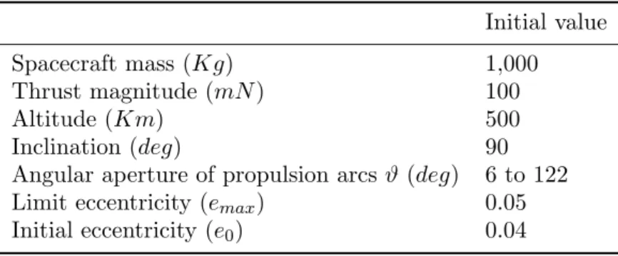
The set of initial conditions for the simulations were listed on Table 1. We used typical values for the thrust and spacecraft mass (see Figures 2 and 3) as well we input the expected value for altitude of a polar orbit reconnaissance satellite.
Table 1. Initial conditions used on the simulations. Initial value
Spacecraft mass (Kg) 1,000
Thrust magnitude (mN) 100
Altitude (Km) 500
Inclination (deg) 90
Angular aperture of propulsion arcsϑ (deg) 6 to 122 Limit eccentricity (emax) 0.05
Initial eccentricity (e0) 0.04
4. Results
Following, the results of our simulations. In each run has been measured the running time (Rt)
needed to keep the excentricity below emax during mission times between 0 and 10,000 days.
From this data, was obtained an empirical expression for the uptime as function of duration of mission.
One can see in Figure 5 that the growth of eccentricity was controled during all the mission time. In that case the colision with Moon surface was properly avoided.
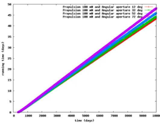
Figure 6 shows the uptime of PMHT as function of duration of mission. Samples of the results forϑ equal to 12o, 32o, 52o and 72o are shown in both figures.
It was performed many linear fit (Rt=A(ϑ)[tk−339.933]) for every tested angular apertures.
The values ofA(ϑ) were plotted in Figure 7 where can be seen that there is a minimum when ϑ is around 12 degrees. Figures 8 and 9 presents basically the same results as previous ones. The main diference is the set of maximum eccentricities maintained.
Figure 5. Stabilization of eccentric-ity values with the correction provided by PMHT. Many sizes of propulsion arcs were considered.
Figure 6. The up time of thrusters as function of the total time used to the simulations.
Figure 7. Angular coeficient A(ϑ), resulted from linear fitting of data shown in Figure 6 versus lenght of propulsion arcs.
One can see (from the Figures 8 and 9) that the sooner the thrusters are activated the lower will be the Angular coeficients A(ϑ) or the running time.
Figure 8. Samples of eccentricties as functions of time.
5. Conclusions
It is confirmed that the growth of eccentricity of a lunar polar satellite orbit can be controlled employing a PMHT in a pulsed manner.
There is the possibility to keep the satellite’s eccentricitystable under 0.05, during a timetk,
with a running time of system given by:
Rt=A(tk−339.933) (7)
The angular coeficientA(ϑ) presents a minimum value when the propulsion arc is around 12 degrees. Therefore we can assume there are an optimal lenght of these angular apertures in order to minimize the fuel consumption. The next step will be the seeking for empirical expressions of optimal ϑas function of eccentricity maintained, altitude and mission time.
Acknowledgments
We are in debt to Brazilian Space Agency (AEB), FAPDF, IFD/UnB, DPP/UnB and the CAPES. Moraes thanks particularly the support of The Brazilian School of Public Administration - ENAP.
References
[1] Estublier, D. , et. al., Electric propulsion on SMART-1 - A technology milestone, 2007, ESA Bulletin, 129, pp. 40 - 46.
[2] Kozai, Y., Secular perturbations of asteroids with high inclination and eccentricity, The Astronomical Journal,vol.67,pp.591-598,1962.
[3] Winter, O. C. et al, “Controlling the Eccentricity of Polar Lunar Orbits with Low Thrust Propulsion” Mathematical Problems in Engineering, vol. on Space Dynamics (2009).
[4] Choueiri, E., A critical history of electric propulsion: the first 50 years (1906-1956),J. Propulsion and Power, Vol. 20, n 2, 2004.
[5] Smith, A. W., Cappelli, M.A., On the role of fluctuations, cathode placement, and collisions on the transport of electrons in the near-field of Hall thrusters,Physics of plasmas, 17, 093501(2010).
[6] Goebel, D., Katz, I., Fundamentals of electric propulsion: ion and hall thrusters, JPL, Pasadena, 2008. [7] Ferreira, J. L. et. al., Plasma Diagnostic and Performance of a Permanent Magnet Hall Thruster,
arXiv:physics/0410170
[8] Santos, D. et. al., Optimal trajectories towards Near-Earth-Objects using solar electric propulsion (SEP) and gravity assisted maneuver, 2008,J. Aerospace Engineering, Vol. 1 - 2, pp. 51 - 64.
[9] Murray, C.D. and Dermott, S.F., Solar system dynamics,Cambridge University Press,1999.