i
Octane Improvement of Gasoline with Porous Solids
Thesis work of Master’s in Chemical Engineering
POLYTECHNIC INSTITUTE OF BRAGANÇA by
Mehriban Aliyeva
Project carried out under the supervision of Prof. Jose A. C. Silva
ii
Abstract
iii
Resumo
iv
Table of contents
1. Introduction 1
1.1. The Isomerization Process for Increasing RON 2
1.2. Zeolites for increasing RON 5
1.3. Metal-Organic Frameworks as an Alternative to Zeolites 6
1.3.1. Metal-Organic Framework with Triangular Channels 6
1.3.2. Zeolitic Imidazolate Frameworks 8
1.4. MOFs vs Zeolites 10
2. Experimental description 12
2.1. Frontal analysis 16
2.2. Experimental set-up 17
3. Experimental conditions and results 19
3.1. MOF MIL-125-Amine 19
3.2. MOF MIL-53 (Fe)-Cl 21
3.3. MOF MIL-53 (Fe)-Br 22
3.4. MOF Fe-TazBz (DMF) 24
4. Conclusion 26
v
List of Figures
Figure 1. A breakdown of the products made from a typical barrel of US oil 1 Figure 2. Schematic situation of a molecular adsorption and desorption with two types of adsorptive
molecules 4
Figure 3. Simplified scheme of the conventional Total Isomerization Process 5 Figure 4. Illustration of the proposed future hexane isomer separation processes 7 Figure 5. Separation of an equimolar mixture of n-hexane and isomers 8
Figure 6. Scheme of processes to increase the RON 9
Figure 7. Comparison of angles in zeolites and ZIFs 9
Figure 8. Research Octane Number; boiling point (Tb) and kinetic diameter (dk) of hexane isomers 10
Figure 9. The schematic rigid structure of MIL-125-Amine 13
Figure 10. 3D structure of MIL-53 (Fe) – Cl 13
Figure 11. Water effect in opening or closing the structure 14
Figure 12. 3D structure of MIL-53 (Fe)-Br 14
Figure 13. Perspective of Fe-TazBz (DMF) by X-rays diffraction 15
Figure 14. Frontal breakthrough curve 16
Figure 15. Mobile phase mass transfer in packed columns 16
Figure 16. Experimental Gas Chromatography set-ups for the breakthrough experiments 17
Figure 17. Experimental equipments 18
vi
List of Tables
Table 1. Typical LSR naphtha composition and components properties 3
Table 2. Alkane components of the quaternary and equimolar mixture used 12
Table 3. Experimental conditions of the equimolar mixture and the loadings obtained in each experience
(MIL-125-Amine) 19
Table 4. Selectivity of the components in experiences (MIL-125-Amine) 20
Table 5. Experimental conditions of the equimolar mixture and the loadings obtained in each experience
(MIL-53(Fe)-Cl) 21
Table 6. Experimental conditions of the equimolar mixture and the loadings obtained in each experience
(MIL-53(Fe)-Br; exp. 1) 22
Table 7. Experimental conditions of the equimolar mixture and the loadings obtained in each experience
(MIL-53(Fe)-Br; exp. 2) 23
Table 8. Experimental conditions of the equimolar mixture and the loadings obtained in each
1
1.
Introduction
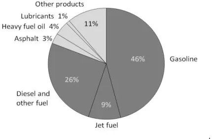
The most part of petroleum is converted to petroleum products, which includes several fuel’s classes [1]. These fuels can be blended and give gasoline, jet fuel, diesel fuel, heating oil, and heavier fuel oils. The refinery yield (percent) is shown on (Fig. 1).
.
Figure 1. A breakdown of the products made from a typical barrel of US oil. Source: eia (U.S Energy Information Administration, 2015) [2].
2
This number is based on the behavior of a mixture of Octane (2,2,4 isooctane), and n-Heptane which is the other major component of standard fuel. A mixture of 90% isooctane and 10% Heptane has a standard resistance to spontaneously brusting into flame.
The resistance gives the value “90” if the amount of isooctane increases to 95% and the n-heptane reduces to 5%, the resistance of the fuel rates as 95%. Also, the high RON improve the performance of the motor. To improve the RON can be used cracking, isomerization, addition of oxygenates (methyl tertiary butyl ether – MTBE) and other processes.
The addition of substances as tetra ethyl lead (TEL) was used in 1990; however, the lead toxicity induced the
environmental protection agency (EPA) to create the program of ‘no lead’ on the manufacturing gasoline. The oxygenates as, methyl tert butyl ether (MTBE, RON 110–112), ethyl tert butyl ether (ETBE, RON 110– 112), tert-amyl methyl ether (TAME, RON 103–105) or ethanol (RON 112–115) were also used but now it is not used because it contaminates drinking water systems. So, it was necessary to find alternatives to improve the enrichment of gasoline without using dangerous additives with environmental impact. To designate the octane number of a gasoline without additives the term clear research octane number (CRON) is also applied.
1.1.
The Isomerization Process for increasing RON.
In order to increase the octane number it was further introduced to reformulate gasoline through the catalytic reforming and the catalytic cracking that are two process that convert paraffins in hydrocarbons with higher octane number. Through the catalytic reforming we convert cycloparaffin to light aromatics (majority in BTX compounds, benzene, toluene and xylenes), while in the catalytic cracking we convert paraffins to light olefins (majority ethylene, propylene and C4s) and both (light aromatics and olefins) have higher octane number than paraffins. Conversely, the aromatics are “Dirty Compounds” due to the harmful emissions to the air and the
olefins are also considered a pollutant but not as dangerous as the aromatics. So it is necessary to reduce the percentage of these products in the gasoline contents to reduce the harmful emissions to the air. Alkylation and isomerization allow the increasing of the octane number without increasing the environmental impact. The alkylation consists the conversion of unsaturated C4’s to high octane isobutanes, while the isomerization processes consist the conversion of other low octane hydrocarbons to the high octane isomers [3].
For the production of gasoline like the feedstock can be used the light-straight-run naphta (LSR), which produced by fraction distillation. The composition of LSR naphtha is listed in (Tab. 1). It includes C5 and C6, which have low RON compared to their branched isomers. Therefore, isomerization is used for changing linear paraffins into branched. The first isomerization process for light naphtha started by Shell in 1970 in La Spezia, Italy (Cusher, 1986b). The Hysomer process is an isomerization process, where the catalyst is a
3
Table 1. Typical LSR naphtha composition and components properties [4].
Component Molecular weight, g/mol Boiling point, 0C LSR naphta,
mol%
RON
Isobutane 58.1 -11.7 0.1 100+
n-butane 58.1 -0.5 0.7 93.6
Isopentane 72.1 27.9 17.5 92.3
n-pentane 72.1 36.1 30.5 61.7
Cyclopentane 70.0 49.3 2.2 100.0
2,2-dimethylbutane 86.2 49.7 0.5 91.8
2,3-dimethylbutane 86.2 58.0 1.8 101.7
2-methylpentane 86.2 60.3 11.2 73.4
3-methylpentane 86.2 63.3 8 74.5
n-hexane 86.2 68.7 17.7 24.8
Methylcyclopentane 84.2 71.8 2.1 91.3
Cyclohexane 84.2 80.7 3.8 83.0
Benzene 78.1 80.1 2.4 100+
Heptane 100.2 98.4 1.6 0.0
The most active catalyst in paraffin isomerization is a bi-functional catalyst, which has a dehydrogenation function and an acid function. It is a platinum loaded mordenite (Pt/H-MOR), platinum on chlorinated alumina (Pt/Al2O3-Cl) and platinum-impregnated sulphated zirconia (Pt/ZrO2-SO42-) (Weyda and Kohler,2003).
With the Hysomer process the RON 10-12 increases until 70-82 depending on the feedstock composition, but
the mixture still contains n-pentane (nPEN) and n-hexane (nHEX) with low RONs. That’s why preferably to
use adsorbents for increasing RON.
4
Figure 2. Schematic situation of a molecular adsorption and desorption with two types of adsorptive molecules [6].
The adsorption corresponds to the stick of the adsorptive molecules of any fluid phase on the surface solid (adsorbent) while desorption corresponds to the return to mobile phase of the molecules placed on the surface phase (adsorbate molecules). When the molecules adsorb and desorb at equal rates adsorption equilibrium occurs [6]. The adsorption separation of the adsorptive molecules is based on three different mechanisms: steric, kinetic and equilibrium mechanisms [7]. The steric separation mechanism is based on the pores and windows dimension that exclude or allow the molecules to enter depending of their size, while the kinetic mechanism is based on the separation through the affinity between the components and the porous structure [6]. The adsorption process reaches equilibrium depending of the adsorbate capacity. The component with the bigger rate of diffusion in the pores and with less affinity is firstly removed in a column. Several factors have influence on the interactions of the molecules with the surface area, such as size and properties. In this specific case of the hexane isomers separation, our goal is the separation preferentially of the di-branched relatively to the linear and mono-branched, so, it is interesting if the di-branched isomer is the more or the less adsorbed on the molecular sieves, because the more important aspect is the selectivity of the di-branched compared with the other components. If a molecular sieve has great adsorption capacity is good, but if the adsorption is equal for all components of the mixture is only important for storage application. For separation applications, the retention time of each component in the column is the more important parameter. The better separation corresponds to the bigger difference in the retention time. Normally we denote the order of
5
1.2.
Zeolites for increasing RON by adsorption processes.
Zeolites are porous crystals with a three-dimensional framework of SiO4 and AlO4 tetrahedral linked to each
other by sharing oxygen atoms. The structural arrangement of the tetrahedral gives rise to a uniform pores system of molecular dimensions. Zeolites are used as separating media for recycling technologies.
Zeolite A is of much interest because its super cage structure is useful in spacio-specific catalysis. Zeolite A, like other zeolites, is synthesized in a gelling process. Sources of alumina (usually sodium aluminate) and silica (usually sodium silicate) are mixed in basic aqueous solution and gives a gel. The alkali agent can be NaOH or solutions of quaternary ammonium salts, amines, or other polar organics. The gel is then heated whre the T = 70-300ºC to crystallize the zeolite. The zeolite is normally synthesized in the Na+ form. The inner cavity is large enough for passing all components, but the small pore means only a specific structure can get into the cavity for reaction, typically n-paraffins and olefins. The small entry pore is selective towards linear paraffins, and cracking can occur on sites within the supercage (alpha-cage) to produce smaller chain alkanes. Zeolite A is also widely used in ion exchange separation.
Beta Zeolite is the unique zeolite with three-dimensional 12-membered ring channels, because of high activity in hydrocracking and hydroisomerization catalyzing. Zeolite Beta is in the list of major catalysts which can be used in organic chemicals conversion, contributing to low waste technology. In comparison with other zeolites, zeolite Beta has unique acid properties which are related to local defects.
The Total Isomerization Process (TIP) uses zeolite 5A to separate normal paraffins. The scheme of Conventional TIP is shown in (Fig. 3). The process has two or four adsorption columns with zeolite 5A. The liquid which contain unconverted linear paraffins vaporizes and passes to the sieve separation unit.
Figure 3. Simplified scheme of the conventional Total Isomerization Process (TIP):
6
This cyclic process consists two steps: adsorption – where n-paraffins are adsorbed in the bed until adsorption has value-75%; desorption – where the bed is cleared from normal paraffins. After they go to the hydroisomerization reactor.
The TIP can produce a final isomerate with 87-90 RON. Zeolite Beta also can be used for the separation of pentane and hexane isomers. Huddersman and Klimczyk (1996a, 1996b) indicated that zeolite beta in cation form (H, Ba) is better than silicalite for the separation of branched hexane isomers.
1.3.
Metal-Organic Frameworks as an Alternative to Zeolites.
Metal-Organic Frameworks (MOFs) are microporous (and nanoporous) materials, which are interesting because of their potential applications in gas storage, selective separation, heterogeneous catalysis. They are synthesized by a simple self-assembly reaction between metals ions and organic linkers under mild conditions . The pores of MOFs can be systematically varied by the judicious choice of the metal ion and/or bridging organic linkers. The smaller molecules can go through the microporous channels while larger molecules are blocked [4]
1.3.1.
Metal-Organic Framework with Triangular Channels.
7
Figure 4. Illustration of the proposed future hexane isomer separation processes. The individual RON of each isomer and the average RON of the final product are included. Current technology uses the small cross-sectional area of n-hexane and a zeolite-sieving process to remove this low-RON isomer from the mixture and return it to the isomerization reactor. In some cases, distillation is then used to further augment the RON of the final product. Given the adsorption selectivity that can be attained within a metal-organic framework (MOF) as demonstrated here for Fe2(BDP)3, it may now be viable to separate only the two most valuable, dibranched isomers from the other three [16].
8
Figure 5. Separation of an equimolar mixture of 2,2-dimethylbutane (red), 2,dimethylbutane(orange), 3-methylpentane (green), 2-3-methylpentane (blue), and n-hexane(purple) running through a packed bed of Fe2(BDP)3 at 160°C [14].
1.3.2.
Zeolitic Imidazolate Frameworks
(ZIF’s)
.
As previously stated, for obtaining a better average RON of the C5/C6 cut, the isomerate is separated in a high octane and a low octane fraction. The low octane fraction is recycled to the catalytic reactor (Fig. 6). This separation can be achieved by distillation, by selective adsorption, or by a combination of both unit operations. The adsorption processes employ zeolite A, which behaves as a molecular sieve. But the mono- and dibranched alkanes can penetrate into the pores of zeolite A, that’s why their separation by zeolite A is not possible. It would, however, be attractive to also recycle the monobranched paraffins to the isomerization reactor, in order to achieve a further improvement of the average RON of the isomerate. It has been proposed to separate the monobranched and dibranched alkanes using a fixed bed of silicalite or zeolite Beta [3; 18-22].
9
Figure 6. Scheme of processes to increase the RON [16].
The majority of the recent studies shows, that for paraffin separation can be used has been dedicated to zeolitic imidazolate frameworks [23,24], for example ZIF-8 [25-29]. In ZIF-8, Zn2+ cations are coordinated to four 2-methylimidazolate ligands (MeIm), resulting in a hybrid material with the topology of the zeolite sodalite (SOD): sodalite cages are connected to each other by six-membered ring windows. The cages have a pore diameter of 1.16 nm and an aperture of 0.34 nm. Two recent studies focused on the adsorption of linear and branched paraffins on ZIF-8 by inverse gas chromatography [30; 31]. They came to the conclusion that linear alkanes can be adsorbed into the cages of ZIF-8, while branched alkanes are sieved out. Thus, the behavior of ZIF-8 is qualitatively similar to zeolite 5A.
ZIFs, which are a subfamily of metal azolate frameworks [32], are, in general, very attractive materials for hydrocarbon separations, because many of them exhibit high porosity and high thermal stability (up to 600 K) [33]. They are built from metal centers linked together by imidazolate units (IM) through their N atoms in the 1,3 positions of the ring. This kind of connection imparts an angle of 145 °C that is close to the T−O−T angle in zeolite frameworks (Fig. 7). As can we see ZIFs have frameworks with the same topologies as zeolites.
10
But ZIFs have larger internal pore diameters than their inorganic homologues. Moreover, recent studies have shown that the pore aperture of many ZIFs is highly flexible [33,34] and allows molecules that are larger than the formal pore opening to be adsorbed, for example, linear alkanes (kinetic diameter 0.43 nm) in ZIF-8 (formal pore opening 0.34 nm).
This study, has compared three ZIF materials in the separation of alkane isomers. And the best was chosen ZIF-8, because it acts as a molecular sieve. Linear alkanes can diffuse freely into the pores of ZIF-8. Monobranched alkanes are adsorbed under strong diffusional limitation, and di-branched alkanes are excluded from the pores. Because the diameter of di-branched larger, and it has more RON (101.7) than monobranched (74.5) (Fig. 8).
Figure 8. Hexane isomers: research octane number (RON); boiling point (Tb) and kinetic diameter (dk) [4].
The effective pore size of ZIF-8 in the paraffin separation is, therefore, comparable to the kinetic diameter of monobranched alkanes, i.e., 0.53 nm. This is much higher than the formal pore size of 0.34 nm and means that the flexibility of the pore aperture of ZIF-8 is much higher than anticipated [16].
1.4.
MOFs vs Zeolites.
11
Recently, it has been shown that zeolite BETA can be used to upgrade actual Total Isomerization Processes [39]. In that work, it is demonstrated that an optimal layered bed of zeolite A-to-zeolite BETA can improve the product average RON up to 1.0 point compared to actual existing TIP processes using zeolite 5A only. Moreover, process simulations demonstrated that increasing the operating temperature from 523 K to 543 K results in an octane gain of 0.2 RON.
Today metal-organic frameworks represent a new class of porous materials proving to be a competitive alternative to zeolites since they combine an important regular porosity with an easily tunable hybrid crystalline framework [40].
The objectives of this work is to evaluate the performance of some MOFs synthesized in Institute Lavoisier de Versailles for the separation of hexane isomers. Actually, zeolite A can segregate normal from branched ones. A major progress will be made if one can find a porous solid that can additionally separate mono from dibranched paraffins. The performance of MOFs will be evaluated by performing experimental screening studies hexane isomers in an experimental unit existing in LSRE-IPB, including:
12
2.
Experimental description
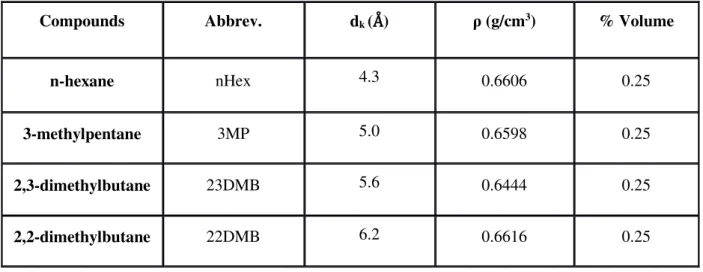
In order to study the adsorption of hexane isomers on MOF’s was packaged the samples with
ceramic wool in a stainless steel column (L= 8 cm, di= 4.6 mm) and introduced continuously a known quaternary composition of alkane equimolar mixture (Tab. 2) in a Helium stream that passed in the column.
Table 2. Alkane components of the quaternary and equimolar mixture used.
Compounds Abbrev. dk (Å) ρ (g/cm3) % Volume
n-hexane nHex 4.3 0.6606 0.25
3-methylpentane 3MP 5.0 0.6598 0.25 2,3-dimethylbutane 23DMB 5.6 0.6444 0.25 2,2-dimethylbutane 22DMB 6.2 0.6616 0.25 The MOF’s that were studied in this work were the MIL-125-Amine, Cl, MIL-53(Fe)-Br and Fe-TazBz(DMF) synthesised. Every MOF were activated in vacuum oven (CHEVREAU, Janvier-Avril 2009).
The schematic rigid structure of MIL-125-Amine (Fig. 9a); cyclic octamers (Fig. 9b) provides a 3D framework (Figure 9c) with one type of cage octahedral (Fig. 9e) and other tetrahedral (Fig. 9e), where the triangular windows of the cages supply the easy access with free apertures in the range 5-7 Å (Meenakshi Dan-Hardi, 2009).
13
Figure 9. (a) Perspective view of a centered cubic arrangement; the12-fold coordination is evidenced by yellow lines. Purple and orange dots indicate the positions of the centers of the tetrahedral and octahedral vacancies. (b) View of the perforated cyclic octamer with edge- and corner-sharing Ti octahedra; it corresponds to the atom with an orange circle of the classical packing through the SBU augmentation. (c) Perspective view of MIL-125 with the central octamer surrounded by 12 others; the pink and blue stars indicate the centers of the tetrahedral and octahedral vacancies in MIL-125.(d) Ball and stick representation of the octahedral vacancy, filled by water molecules (in green); the large yellow sphere represents the effective accessible volume of the cage. (e) The tetrahedral vacancy; in (d) and (e) the color code is as follows: carbon, gray; oxygen, red; water, green; titanium, yellow, in (Meenakshi Dan-Hardi, 2009) [41].
The MIL-53 (Fe)-Cl has windows with lozenge form that make in structure open channels (Fig. 10). This framework is flexible and open or close when hydrated or dehydrated (Fig. 11). The kinetic diameter of access window is 7.4 or 7.7 if were in hydrated or dehydrated form respectively (Thomas Devic, 2009).
14
Figure 11. Water effect in opening or closing the structure [42].
The crystals of MIL-53 (Fe)-Cl used in this study were in powder form, packaged with ceramic wool only in both ends of the column. The sample was activated in vacuum oven at nearly -90 kPa during 15 h at 200 ºC, before the packing. Therefore this activation the MOF was study at dehydrated form.
The MIL-53 (Fe)-Br (Fig. 12) is also flexible and similar to MIL-53 (Fe)-Cl in structure with lozenge windows that make channels and the structure is open or close when hydrated or dehydrated. The kinetic diameter of access window is 8.0 if were in hydrated or dehydrated form (Thomas Devic, 2009).
Figure 12. 3D structure of MIL-53 (Fe)-Br [42].
15
The Fe-TazBz (DMF) has a rigid cubic structure (Figure 13d). The diameter of access window range 5-7Å and this interception make cages with diameter superior than 10 Å (CHEVREAU, Janvier-Avril 2009).
Figure 13. Perspective of Fe-TazBz (DMF) by X-rays diffraction. a) Trimer of of iron carboxylate [Fe3O (CO2) 6 (H2O) 3] which can be viewed as a node in the trigonal prismatic with 6
connections; b) Organic binder (acid (3, 3 ', 5, 5’ - azobenzenotétracarboxilato))plane rectangular geometry, with four connections; c) Molecule trapped in the cavity d) Polyhedral representations of the cubic cages; The color code is as follows: Fe, green; C, gray; N, blue, O, red. The diameter of the vacancy is indicated by yellow sphere (CHEVREAU, Janvier-Avril 2009) [43].
16
2.1.
Frontal Analysis
In frontal analysis, the mixture is continuously injected to the column for the separation of components. On the Fig. 14 is shown a breakthrough curve .
Figure 14. Frontal breakthrough curve [44].
The chromatographic technic for separation is based on the affinity difference between the adsorbent and each component. And the retention time of the components in the column is different because of the affinity. The equation 1 shows how the retention time (tr) in the column changes with the velocity (u) of the components with a certain length (L), when they are passing in the column with a certain length (L).
(1)
The Fig. 15 shows the mobile phase mass transfer in a packed column. In this case tr3> tr2> tr1, so, the u3< u2<u1. The equimolar mixture (1, 2, 3) and carrier gas arrive to the outlet of the column at different times because of their affinity. Their flow rates are constant .
Figure 15. Mobile phase mass transfer in packed columns; tr3> tr2> tr1 [44].
17
2.2.
Experimental set-up
The breakthrough of single and multicomponent experiments were performed in a Gas Chromatograph (GC) SRI model 8610c (Fig. 16a). This model was adapted specifically for this specific experiments. The mixture to is introduced by a syringe pump (Fig. 16b) in the carrier gas before entering in the column. A heating chamber (evaporator) vaporizes completely the liquid mixture. The adsorption column consists in a 4.6 mm i.d. stainless steel column with 100 mm in
length containing the adsorbent and placed in the ventilated chromatographic oven (Fig 17a), as well as a heated collector with 10 loops (Fig 17b) to collect samples at the outlet of the column.
a) b)
Figure 16. Experimental Gas Chromatography (GC) set-ups for the breakthrough experiments, where is showed the (a) GC equipment [left: SRI model 110, centre: SRI model 8610c with exhaustion of vapours, right: computer] and mass flow controller (MFC), most to the right. (b) Injection and control pressure part [Top left: Injector port connected to the evaporator, Top right: syringe pump; Bottom left: Back Pressure control (BPC)] [45].
The analytical section is composed by a chromatographic column and a flame ionization detector (FID) (Fig 17c). Complete information about the experimental setup is reported elsewhere Bárcia
18
a) b) c)
19
3.
Experimental Conditions and Results
3.1.
MOF MIL-125-Amine
The experiments were performed at 100 and 150ºC, for high (0,06bar) and low partial pressure (0,006bar). The room temperature of the experiences was nearly 20 ºC. The experimental conditions and the quantity adsorbed of each component in mixture (loadings) are expressed in Table 3.
Table 3. Experimental conditions of the equimolar mixture and the loadings obtained in each experience for MOF MIL-125-Amine.
Run T(oC)
Partial P(bar) He flow (mL/min) Mix. Flow (µL/hr) mads (mg)
Loadings g/100gads Total
(g/100
gads)
22DMB 23DMB 3MP nHex
3.1
150
0.06 15 310
0.1943
1.49 2.16 2.31 3.46 9.43
3.2
0.006 40 80
0.49 0.65 0.79 1.19 3.13
3.3
100
0.90 1.30 1.65 2.38 6.23
3.4 0.06 15 310 2.61 3.45 4.08 5.13 15.27
20
Table 4. Selectivity of the components in experiences with MOF MIL-125-Amine.
Selectivity
Temperature (ºC) 150 100
Pressure (bar) 0.06 0.006 0.06 0.006
nHex/22DMB 2.32 4.40 1.96 2.64
nHex/23DMB 1.60 2.56 1.49 1.83
nHex/3MP 1.49 1.75 1.26 1.45
3MP/22DMB 1.55 2.52 1.56 1.82
3MP/23DMB 1.07 1.47 1.18 1.27
23DMB/22DMB 1.45 1.72 1.32 1.44
The fig. 18 shows the breakthrough of each experience, where we can observe that the affinity order of the hexane isomers is n-Hex > 3MP > 23DMB > 22DMB.
a) b)
c) d)
Figure 18. Breakthrough curves in different conditions for MOF MIL-125-Amine: a) T=1500C, P=0.06 bar; b) T=1500C, P=0.006 bar; c) T=1000C, P=0.006 bar; d) T=1000C, P=0.06 bar.
C/
Co
Time (min)
Exp 3.1, T=150 ºC, P=0.06 bar
22DMB 23DMB 3MP n-hex C/ Co Time (min)
Exp 3.2 T=150 ºC, P=0.006 bar
22DMB 23DMB 3MP n-hex C/ Co Time (min)
Exp 3.3 T=100 ºC, P=0.006 bar
22DMB 23DMB 3MP C/ Co Time (min)
Exp 3.4, T=100 ºC, P=0.06 bar
21
The Breakthroughs show a diminutive time out of curves and a little difference in each component. The access windows of the MOF range 5 and 7 Å and the kinetic diameter of hexane isomers is 4.3, 5.0, 5.6 and 6.2 for nHex, 3MP, 23DMB and 22DMB respectively, then, the nHex enter in both types of cages, while 3MP, 22DMB and 23DMB enter only in one type. This fact justifies the better adsorption of hexane than the other components.
3.2.
MOF MIL-53(Fe)-Cl
The experiments were performed only at 150ºC, for high (0,06bar) and low partial pressure (0,006bar) because is clearly through the loadings (Tab. 5) and breakthroughs (Fig. 19) that the adsorption is a few and the time out of curves is almost immediate, then isn’t made more studies.
The room temperature of the experiences was nearly 20 ºC.
Table 5. Experimental conditions of the equimolar mixture and the loadings obtained in each experience for MOF MIL-53(Fe)-Cl.
Run T (ºC) Partial
P (bar)
He flow
(ml/min)
Mix. flow
(l/hr)
mads
(mg)
Loadings (g/100 gads) Total
(g/100 gads)
22DMB 23DMB 3MP nHex
Run 5.1
150
0.06 15 310
0.4913
0.97 0.89 0.86 0.78 3.49
Run 5.2
0.006 40 80 0.06 0.05 0.05 0.04 0.21
a) b)
Figure 19. Breakthrough curves in different conditions for MOF MIL-53(Fe)-Cl: a) T=1500C, P=0.06 bar; b) T=1500C, P=0.006 bar.
C/
Co
Time(min)
Exp 5.1, T=150 ºC, P=0.06 bar
22DMB 23DMB 3MP n-hex C/ Co Time (min)
Exp 5.2, T=150 ºC, P=0.006 bar
22
Through the breakthroughs is clearly notable that not exist separation of components. This fact will can be explained by the aperture of the MOF (7.4 Å) to be bigger than kinetic diameter of all components and his possible poor affinity with the hexane isomers, leaving to pass them. Despite this results can observe that a little affinity order of the hexane isomers is 22DMB > 23DMB >3MP > n-Hex, different of MIL-125-Amine.
3.3.
MOF MIL-53(Fe)-Br
The first part of experiments was performed only at 150ºC, for high (0,06bar) and low partial pressure (0,006bar) because also the low adsorption (Tab. 6) and the time out of curves is almost immediate (Fig. 20), then isn’t made more studies. The room temperature of the experiences was nearly 21 ºC.
Table 6. Experimental conditions of the equimolar mixture and the loadings obtained in each experience for MOF MIL-53(Fe)-Br.
Run T (ºC) Partial P (bar) He flow (ml/min) Mix. flow
(l/hr)
mads
(mg)
Loadings (g/100 gads) Total
(g/100 gads)
22DMB 23DMB 3MP nHex
Run 6.1
150 0.06 15 310 0.3595 0.43 0.41 0.39 0.35 1.58
Run 6.2
0.006 40 80 0.02 0.02 0.02 0.02 0.09
a) b)
Figure 20. Breakthrough curves in different conditions for MOF MIL-53(Fe)-Br: a) T=1500C, P=0.06 bar; b) T=1500C, P=0.006 bar.
C/
Co
Time (min)
Exp 6.1, T=150 ºC, P=0.06 bar
22DMB 23DMB 3MP n-hex C/ Co Time (min)
Exp 6.2, T=150 ºC, P=0.006 bar
23
These results are similar to the MOF MIL-53 (Fe)-Cl and through the breakthroughs is also notable that not exist separation of components. This fact will can be explained by the aperture of the MOF (8.0 Å) to be bigger than kinetic diameter of all components and also his possible poor affinity with the hexane isomers, leaving to pass them. The affinity order of components is the same.
The second part of experiments was performed only at 150ºC, for high (0,06bar) and low partial pressure (0,006bar) also because the low adsorption (Tab. 7) and the time out of curves is almost immediate (Fig. 21), then isn’t made more studies. The room temperature of the experiences was nearly 21 ºC.
Table 7. Experimental conditions of the equimolar mixture and the loadings obtained in each experience for MOF MIL-53(Fe)-Br.
Run T (ºC) Partial P (bar)
He flow
(ml/min)
Mix. flow
(l/hr)
mads
(mg)
Loadings (g/100 gads) Total
(g/100 gads)
22DMB 23DMB 3MP nHex
Run 7.1
150 0.06 15 310 0.4169 1.56 1.18 1.15 1.07 4.97
Run 7.2
0.006 40 80 0.13 0.12 0.13 0.13 0.51
a) b)
Figure 21. Breakthrough curves in different conditions for MOF MIL-53(Fe)-Br: a) T=1500C, P=0.06 bar; b) T=1500C, P=0.006 bar.
C/
Co
Time (min)
Exp 7.2, T=150 ºC, P=0.006 bar
22DMB 23DMB 3MP n-hex C/ Co Time (min)
Exp 7.1, T=150 ºC, P=0.06 bar
24
These results are similar to the MOF MIL-53 (Fe)-Cl and MIL-53 (Fe)-Br in agglomerate form, then, invited to study these MOFs in hydrated form and under low temperatures.
3.4.
MOF Fe-TazBz(DMF)
The experiments were performed at 150, 100 and 70ºC, for high (0,06bar) and low partial pressure (0,006bar). The room temperature of the experiences was nearly 21 ºC. The experimental conditions and the quantity adsorbed of each component in mixture are expressed in Tab. 8.
Table 8. Experimental conditions of the equimolar mixture and the loadings obtained in each experience for MOF Fe-TazBz(DMF).
Run T (ºC) Partial P (bar) Helium flow (ml/min) Mix. flow
(l/hr)
Loadings (g/100 gads) Total
(g/100 gads)
22DMB 23DMB 3MP nHex
Run 7.1
150
0.06 15 310 0.49 0.64 0.86 5.47 7.46
Run 7.2
0.006 15 30
0.06 0.07 0.07 0.53 0.73
Run 7.3
100
0.06 0.06 0.06 0.47 0.64
Run 7.4
0.06 15 310
0.31 0.42 0.52 5.85 7.10
Run 7.5
70
0.56 0.67 0.77 6.25 8.24
Run
7.6 0.006 15 30 0.07 0.08 0.09 0.56 0.79
25
a) b)
c) d)
c) f)
Figure 22. Breakthrough curves in different conditions for MOF Fe-TazBz(DMF): a) T=1500C, P=0.06 bar; b) T=1500C, P=0.006 bar; c) T=1000C, P=0.06 bar; d) T=1000C, P=0.006 bar; e) T=700C, P=0.06 bar; f) T=700C, P= 0.006 bar.
Separation of components was better than with MOF MIL-125-Amine because of higher affinity of n-hex with this MOF.
C/
Co
Time (min)
Exp 8.1, T=150 ºC, P=0.06 bar
22DMB 23DMB 3MP n-hex C/ Co Time (min)
Exp 8.2, T=150 ºC, P=0.006 bar
22DMB 23DMB 3MP n-hex C/ Co Time(min)
Exp 8.4, T=100 ºC, P=0.06 bar
22DMB 23DMB 3MP n-hex C/Co Time (min)
Exp 8.3, T=100 ºC, P=0.006 bar
22DMB 23DMB 3MP n-hex C/ Co Time (min)
Exp 8.5, T=70 ºC, P=0.06 bar
22DMB 23DMB 3MP n-hex C/ Co Time (min)
Exp 8.6, T=70 ºC, P=0.006 bar
26
4.
Conclusion
In this work was studied the adsorption of hexane isomers in Metal-Organic Frameworks (MOFs) like MIL-125-Amine, MIL-53(Fe)-Cl, MIL-53(Fe)-Br and Fe-TazBz(DMF), it can be concluded the bigger adsorption was obtained for high pressure and low temperature. It was not observed adsorption of the researched components for low pressure. With MOFs 53(Fe)-Cl, MIL-53(Fe)-Br components weren’t separated. When was used MIL-125-Amine hexane isomers were separated according to the boiling point of the compounds, but observed selectivity was low. The Fe-TazBz(DMF) showed the best result because of the higher affinity of n-hex with this MOF for separating it from the other isomers.
27
5.
References
[1] D, Jones, An introduction to crude oil and its processing, in: Handbook of Petroleum Processing, Springer, USA, (2006).
[2] https://en.wikipedia.org/wiki/Petroleum_product#cite_note-2 (12.07.2016)
[3] Walther W. Irion, Otto S. Neuwirth, "Oil Refining" in Ullmann's Encyclopedia of Industrial Chemistry 2005, Wiley-VCH, Weinheim. doi:10.1002/14356007.a18_051
[4] Patrick Da Silva Barcia, Separation of Light Naphtha for the Octane Upgrading of Gasoline, (2010).
[5] B. Chen, C. Liang, J. Yang, D. Contreras, Y. Clancy, E. Lobkovsky, O. Yaghi, S. Dai, A Microporous Metal–Organic Framework for Gas-Chromatographic Separation of Alkanes, Angew. Chem. Int. Ed., 45 (2006) 1390-1393.
[6] J. Keller, R. Staudt, Gas Adsorption Equilibria Experimental methods and Adsorption Isotherms, Springer , Germany, (2005).
[7] D. Do, Adsorption analysis: Equilibria and Kinetics, ICP, Australia, (1998).
[8] M. Eddaoudi et al., Science 295, 469 (2002).
[9] S. Kitagawa, R. Kitaura, S.-i. Noro, Angew. Chem. Int. Ed.43, 2334 (2004).
[10] G. Férey, Chem. Soc. Rev. 37, 191 (2008).
[11] A. U. Czaja, N. Trukhan, U. Müller, Chem. Soc. Rev. 38, 1284 (2009).
[12] D. H. Desty, W. T. Swanton, J. Phys. Chem. 65, 766 (1961).
[13] R. A. Myers, Ed., Handbook of Petroleum Refining Processes (McGraw-Hill, New York,
28
[14] R. Clavier, Ed., Wiley Critical Content: Petroleum Technology (Wiley-Interscience, Hoboken, NJ, 2007).
[15] R. V. Jasra, S. G. T. Bhat, Sep. Sci. Technol. 23, 945 (1988).
[16] David Peralta, Gérald Chaplais, Angélique Simon-Masseron, Karin Barthelet, and Gerhard D. Pirngruber, Separation of C6 Paraffins Using Zeolitic Imidazolate Frameworks: Comparison with Zeolite 5A, Ind. Chem. Res. (2012), 51, 4692-4702.
[17] F. Nadim, P. Zack, G. E. Hoag, S. Liu, Energy Policy 29, 1 (2001).
[18] Barcia, P. S.; Zapata, F.; Silva, J. A. C.; Rodrigues, A. E.; Chen, B. Kinetic Separation of Hexane Isomers by Fixed-Bed Adsorption with a Microporous Metal-Organic Framework. J. Phys. Chem. B (2007), 111, 6101.
[19] Dubbeldam, D.; Galvin, C. J.; Walton, K. S.; Ellis, D. E.; Snurr, R. Q. Separation and Molecular-level Segregation of Complex Alkane Mixtures in Metal-Organic Frameworks. J. Am. Chem. Soc. (2008), 130, 10884.
[20] Jiang, J. W.; Sandler, S. I. Monte Carlo Simulation for the Adsorption and Separation of Linear and Branched Alkanes in IRMOF-1. Langmuir (2006), 22, 5702.
[21] Zhang, L.; Wang, Q.; Wu, T.; Liu, Y. C. Understanding Adsorption and Interactions of Alkane Isomer Mixtures in Isoreticular Metal-Organic Frameworks. Chem.-Eur. J. (2007), 13, 6387.
[22] Van den Bergh, J.; Gucuyener, C.; Pidko, E. A.; Hensen, E. J. M.; Gascon, J.; Kapteijn, F. Understanding the Anomalous Alkane Selectivity of ZIF-7 in the Separation of Light Alkane/Alkene Mixtures. Chem.-Eur. J. 2011, 17, 8832.
[23] Gucuyener, C.; van den Bergh, J.; Gascon, J.; Kapteijn, F. Ethane/ Ethene Separation Turned on Its Head: Selective Ethane Adsorption on the Metal−Organic Framework ZIF-7 through a Gate-Opening Mechanism. J. Am. Chem. Soc. (2010), 132, 17704.
[24] Cousin Saint Remi, J.; Remy, T.; Van Hunskerken, V.; van de Perre, S.; Duerinck, T.; Maes, M.; De Vos, D.; Gobechiya, E.; Kirschhock, C. E. A.; Baron, G. V.; Denayer, J. F. M. Biobutanol Separation with the Metal Organic Framework ZIF-8. ChemSusChem (2011), 4, 1074.
29
[26] Chang, N.; Gu, Z. Y.; Yan, X. P. Zeolitic Imidazolate Framework-8 Nanocrystal Coated Capillary for Molecular Sieving of Branched Alkanes from Linear Alkanes along with High-Resolution Chromatographic Separation of Linear Alkanes. J. Am. Chem. Soc. (2010), 132, 13645.
[27] Luebbers, M. T.; Wu, T.; Shen, L.; Masel, R. I. Effects of Molecular Sieving and Electrostatic Enhancement in the Adsorption of Organic Compounds on the Zeolitic Imidazolate Framework ZIF-8. Langmuir (2010), 26, 15625.
[28] Li, K.; Olson, D. H.; Seidel, J.; Emge, T. J.; Gong, H.; Zeng, H.; Li, J. Zeolitic Imidazolate Frameworks for Kinetic Separation of Propane and Propene. J. Am. Chem. Soc. (2009), 131, 10368.
[29] Ruthven, D. M. Principles of Adsorption and Adsorption Processes; (1984).
[30] Peralta, D.; Chaplais, G.; Simon-Masseron, A.; Barthelet, K.;Pirngruber G. D. Synthesis and Adsorption Properties of ZIF-76 Isomorphs. Microporous Mesoporous Mater. (2012), 153, 1.
[31] Zhang, J. P.; Zhang, Y. B.; Lin, J. B.; Chen, X. M. Metal Azolate Frameworks: From Crystal Engineering to Functional Materials. Chem. Rev. (2011), 112, 1001.
[32] Park, K. S.; Ni, Z.; Cote, A. P.; Choi, J. Y.; Huang, R. D.; Uribe- Romo, F. J.; Chae, H. K.;
O’Keeffe, M.; Yaghi, O. M. Exceptional Chemical and Thermal Stability of Zeolitic Imidazolate Frameworks. Proc. Natl. Acad. Sci. U.S.A. (2006), 103, 10186.
[33] Fairen-Jimenez, D.; Moggach, S. A.; Wharmby, M. T.; Wright, P. A.; Parsons, S.; Duren, T. Opening the Gate: Framework Flexibility in ZIF-8 Explored by Experiments and Simulations. J. Am. Chem. Soc. (2011), 133, 8900.
[34] Moggach, S.; Bennett, T.; Cheetham, A. The Effect of Pressure on ZIF-8: Increasing Pore Size with Pressure and the Formation of a High-Pressure Phase at 1.47 GPa. Angew. Chem. Int. Ed. (2009), 121,7221.
[35] G., Férey, Some suggested perspectives for multifunctional hybrid porous solids, Chem. Soc. Rev., Dalton Trans, (2009) 4400-4415.
30
[37] J. Stuart, Metal-organic frameworks., Chem. Soc. Rev., 32 (2003) 276–288.
[38] J. Rowsell, O. Yhagi, Metal-Organic Frameworks: a new class of porous, Micropor. Mesopor. Mater., 73 (2004) 3-14.
[39] P. Bárcia, J. Silva, A. E. Rodrigues, Multicomponent Sorption of Hexane Isomers in Zeolite BETA, AIChE Journal, 53(2007)1970-1981.
[40] P. Mendes, F. Ragon, A. E. Rodrigues, P. Horcajada, C. Serre, J. Silva, Hexane isomers sorption on a functionalized metal–organic framework, Microporous and Mesoporous Materials, 170 (2013) 251–258.
[41] A New Photoactive Crystalline Highly Porous Titanium(IV) Dicarboxylate [Journal] / auth. Meenakshi Dan-Hardi Christian Serre, Théo Frot, Laurence Rozes, Guilhaume Maurin, Clément Sanchez, and Gérard Férey. - [s.l.] : J. Am. Chem. Soc., (2009).
[42] Functionalization in Flexible Porous Solids: Effects on the Pore Opening and the Host-Guest Interactions [Journal] / auth. Thomas Devic Patricia Horcajada, Christian Serre, Fabrice Salles, Alexandre Vimont, Jean-Marc Grenèche, Benjamin Le Ouay, Florian Moreau, Emmanuel Magnier,Yaroslav Filinchuk, Jerôme Marrot, Jean-Claude Lavalley, Marco Daturi, and Gérard Férey. - [s.l.] : J. AM. CHEM. SOC., (2009).
[43] Synthèse de MOFs [Report]: Rapport d'activité / auth. CHEVREAU Hubert / Institut Lavoisier, Universite de Versailles Saint-Quentin-En-Yvelines. - Versailles : [s.n.], Janvier-Avril (2009). - UMR CNRS 8180.
[44] H. McNair, J. Miller, Basic Gas Chromatography, 2nd ed., Wiley, USA (2009).
![Figure 2. Schematic situation of a molecular adsorption and desorption with two types of adsorptive molecules [6]](https://thumb-eu.123doks.com/thumbv2/123dok_br/16812942.750981/10.892.217.680.83.406/figure-schematic-situation-molecular-adsorption-desorption-adsorptive-molecules.webp)


![Figure 5. Separation of an equimolar mixture of 2,2-dimethylbutane (red), 2,3-dimethylbutane(orange), 3- 3-methylpentane (green), 2-3-methylpentane (blue), and n-hexane(purple) running through a packed bed of Fe 2 (BDP) 3 at 160°C [14]](https://thumb-eu.123doks.com/thumbv2/123dok_br/16812942.750981/14.892.184.714.92.405/figure-separation-equimolar-mixture-dimethylbutane-dimethylbutane-methylpentane-methylpentane.webp)
![Figure 6. Scheme of processes to increase the RON [16].](https://thumb-eu.123doks.com/thumbv2/123dok_br/16812942.750981/15.892.193.711.90.391/figure-scheme-processes-increase-ron.webp)
![Figure 8. Hexane isomers: research octane number (RON); boiling point (T b ) and kinetic diameter (d k ) [4]](https://thumb-eu.123doks.com/thumbv2/123dok_br/16812942.750981/16.892.269.635.408.632/figure-hexane-isomers-research-octane-boiling-kinetic-diameter.webp)

![Figure 11. Water effect in opening or closing the structure [42].](https://thumb-eu.123doks.com/thumbv2/123dok_br/16812942.750981/20.892.141.781.100.313/figure-water-effect-opening-closing-structure.webp)
