Mean Field J
C
Estimation for Levitation Devie
Simulations in the Bean Model Using Permanent
Magnets and YBCO Superonduting Bloks
MareloAzevedo Neves 1
,GianarloCordeiro daCosta 2
, Agnaldo SouzaPereira 3
,
Rubens de AndradeJr. 1
, and Roberto Niolsky 3
1
LASUP,DEE-Dep. deEletrotenia, Esolade Engenharia,
UFRJ-UniversidadeFederaldoRio deJaneiro,
Cx. P.68.553,21945-970, RiodeJaneiro,Brazil,
2
LAMCE,PEC-COPPE,UFRJ,21945-970, Rio deJaneiro,Brazil
3
Institutode Fsia,UFRJ,21945-970,Riode Janeiro, Brazil
Reeivedon28February,2002
Thisworkpresentsameaneld estimationofJC as abulkharateristi ofYBCObloks. That
average J
C
allows a goodttingof thenite-element-method(FEM)simulationofthe levitation
forestoexperimentalresults. Thatagreementisquiteenoughforlevitationrequirementsofdevie
projets,atshortgapsandzeroeldoolingproess,withintheBeanmodel. Thephysial
hara-terization forthat estimationwas mademeasuringtheinterationforebetweenthePMandone
YBCOblokin1-Dandmappingthetrappedmagnetieldinthosebloksin2-D.
I Introdution
Superondutingmelttextured(MT)YBCObloksare
extremely important materials to the development of
stable levitatingdeviesasbearings,forexample. The
designoflevitatingsystems(aslinearorrotating
bear-ings) using high temperature superonduting (HTS)
materials requires large bulk speimens with highly
alignedandwellonnetedgrains[1℄. Thisisahieved
usingmelttexturedgrowth(MTG)proess,usuallyby
top-seedingmethods[2℄. Suhsamplesallowlarge
ur-rentloopsandhigh valuesofJ
C .
Theuse of nite element method (FEM) improves
the projet of levitating devies. But in order to
ap-ply a ommerial FEM software, the response of the
MTG HTSbloktoanappliedmagneti eldmustbe
informedbytheuser. Thatresponse isrepresentedby
a B =B(H) urve [4℄ foreah partiular sample
on-sidered. To our knowledge, up to date, there is not
any FEM software able to work with HTS materials
properly. However,within theframework of the Bean
CritialStateModel(BCSM)[3℄,theB=B(H)anbe
onstruted,onethemeaneldvalueofJ
C
isknown.
Thus,theprojetsofanylevitatingdeviesusingFEM
requires theuseofthevalueofJ
C [5℄.
That atual J
C
value isaparameter that depends
on the overall strutural features of the MTG T
ype-II HTS bloks (mainly on the distribution of pinning
enters). Themean J hasusuallybeenevaluated
us-ingonlyasmall pieeextratedfrom theMTGblok.
With itsmagnetimoment measuredwithavibrating
samplemagnetometer(VSM),oneanevaluatetheJ
C
by the BCSM [3℄. That evaluation has the
inonve-nieneofdamageordestrutionofthebloktobeused
as levitation element and, additionally, that result is
stronglydependentonthe partiularloal ofthe
sam-pleextration. Adesirable evaluationofJ
C
mustusea
non-destrutiveandoverall(bulk)responseofthe
spe-imen,insteadofaloalizedone.
Weproposeanon-destrutivemethodologyto
eval-uatetheaverage(\Bean")J
C
valueusedin FEM
sim-ulations,whihisaurateenoughtoprojetlevitating
devies. Theoverall,orbulk,responseusedtovalidate
theJ
C
valueomesfromthe\levitationfore"urveof
thespeimen.
II Methodology
The proposed methodology employs nite element
method(FEM)andtheBCSMinordertosimulatethe
interation fore between a permanent magnet (PM)
andaMTGHTSblok,thesoalled\levitationfore"
[5℄. The ux density B due to the magnetization
re-sponse M to the applied eld H is expressed by usual
relationshipB =
0
(H+M),where M is alsoa
fun-tion of the geometry. Byusing the BCSM, for
relation:
B(H)=
0
H 2
H
P H
3
3H 2
p
(1)
where H
P =J
C
R is the full penetration eld [3℄. As
the sample radius R is measured, J
C
is the only free
parameter. Thevalue ofJ
C
anbeadjusted to
gener-ate theB(H) urveof the MTG HTS levitating blok
that allowstheFEMsoftwareto reprodue(simulate)
the measured HTS-PM interation fore (\levitation
fore")urve.
WeusedasMEFsoftwaretheANSYSMultiphysis
5.7 [4℄and the PM-HTS interation (levitation) fore
wasalulatedusingMaxwellTensorapproah[4℄.
Thelevitationforemeasurementsemployeda
soft-wareontrolledequipment(builtinLASUPin
oopera-tiontoICMAB stapersonnel)whereaSmCoPM
(di-ameter=19.00mm,thiknesst=6.40mm,surfae
entraleldB
S
=-0.169T)isattahedtoaommerial
loadell(UTILCELL,mod120). Quasistati
measure-mentsare performed (0.2mm eah step, 2.5 mm/min
san) while the SmCo PM vertially approahes to a
tightly xed MTG HTS blok at 77.4 K (ZFC). A
set of eight ylindrial MTG HTS YBCO omposites
(123+211) bloks made by the same method [6℄ was
analyzed. One all ofthem were madewith the same
onditionsandhavethesamegeometrialfeatures
(di-ameter=26.00 mmandheighth=17.00mm),the
J
C
value, B(H) urve and reation fore in response
totheapproahingSmCoPMshouldbeessentiallythe
sameforallofthem.
The SmCoB(H) urve is already present in the
ANSYS databankandtheMTGHTSB(H)urvewas
builthangingtheJ
C
valueuntilthebestttingofthe
levitationforeurveswasfound.
The MTG HTS bloks were also haraterized
by 2D mapping of the trapped magneti eld. A
BRUKER eletromagnet was employed as
homoge-neouseld soure,the appliedeld was0.5 Tandthe
mapping was made using a Hall sensor (TOSHIBA,
mod THS118) attahed to a software ontrolled X-Y
positioning table built at LASUP (0.4 mm eah step,
1mm/ssan,totalareasan time30min).
III Results and disussion
Thebestmeaneld J
C
valuefoundwas710 7
A/m 2
,
ofthesameorderofmagnitudeofthemeasuredvalues
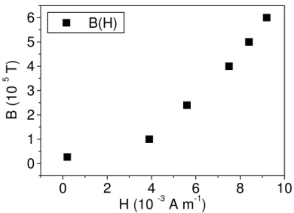
B(H)urveisshowninFig 1. ThesimulationbyFEM
wasbestperformedwiththat urve,see Fig2,and all
themeasuredlevitationforeurveswerewelltted,as
anbeseenin Fig3.
0
2
4
6
8
10
0
1
2
3
4
5
6
B(H)
B(
1
0
5
T)
H (10
-3
A m
-1
)
Figure1.ThebestB(H)inputdatafortheMTGHTS
blokswithsamedimensions(seetext).
Theeld mappingofthebloksispresentedin Fig
4. As an be seen, the maximum trapped eld is
al-most the sameto allsamples (2.5 kG = 0.25T), but
the prole hangesfrom sample to sample,mainly for
largerdistanesfromtheenter.
That average J
C
valueallowedasimulationof the
levitationforein allthemeasuredrange(40mm)not
sensitive,inlinearsale,tothosedierenttrappedeld
proles.
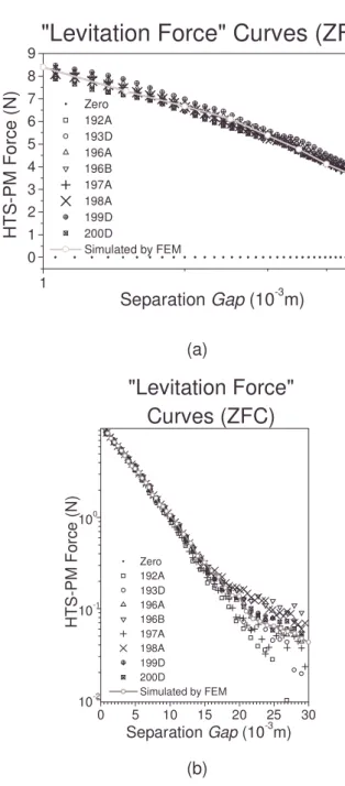
Detailsofthelevitationurves,seeninFig.5at
log-arithmisale,showthat forsmalldistanes(lessthan
5mm)thesimulatedandmeasuredurvesarein good
agreementforallsamples. Forlargedistanes
(separa-tiongreaterthan 20mm)somesimulatedfore urves
deviatefromthemeasuredoneswithoutanylear
pat-tern. However, the distanes smaller than 5 mm are
theusualonesemployedin levitationdevies.
Onetheeldmappingindiateseahblokhas
dif-ferenturrentloopproles,theuseofBeanmodelwas
notabletotakeintoaountsuhnonhomogenous
fea-tureinordertogeneratetheB(H)responseurve. But
the resultsindiate suhdeviation do notaet
simu-lationsdevotedtolevitationprojets.
Newstudiesarenowontheirwaysinorderto
eval-uatetherelationamongthelevitationforeurves,the
bestaverageJ
C
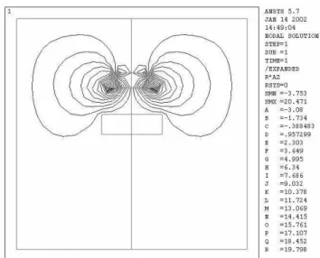
Figure2. SimulatedinterationbetweentheSmCoPMandtheMTGHTSblok. Separationdistanebetweenthemvaried
withintworanges: 0.5mmand1mmsteps.
=HUR
$
'
$
%
$
$
'
'
6LPXODWHGE\)(0
/HYLWDWLRQ)RUFH&XUYHV=)&
+
76
3
0
)
R
UF
H
1
6HSDUDWLRQ
*DS
P
Figure 3. Measured and simulated PM-HTS interation
(\levitation") foreurvesas funtionofPM-HTS
separa-tiongap,linearsales.
IV Conlusions
We proposed and employed a non-destrutive new
methodology to estimate the mean eld J
C
of large
MTG HTS bloks, based on an overall (\bulk")
re-sponse: thelevitationforeurve.
Inourapproah,thataverageJ
C
valueisafree
pa-rameterusedto onstruttheB(H) urveoftheMTG
HTS blok, as required by the FEM software to
sim-ulate its levitation fore urve. The evaluated J
C is
validated tolevitation requirementsof devie projets
bythe goodagreementbetweendiretlymeasured and
simulatedlevitationforeurves,speiallyatsmall
dis-tanes.
ForlargergapsbetweenthePMandtheMTGHTS
1
0
1
2
3
4
5
6
7
8
9
Zero
192A
193D
196A
196B
197A
198A
199D
200D
Simulated by FEM
"Levitation Force" Curves (ZFC)
HT
S-PM
Fo
rc
e
(N)
Separation
Gap
(10
-3
m)
(a)
0
5
10
15
20
25
30
10
-2
10
-1
10
0
Zero
192A
193D
196A
196B
197A
198A
199D
200D
Simulated by FEM
"Levitation Force"
Curves (ZFC)
H
T
S-PM
F
o
rc
e
(N
)
Separation
Gap
(10
-3
m)
(b)
Figure5. DetailsonmeasuredandsimulatedPM-HTS
in-teration(\levitation")foreurves,logarithmisales(see
eld prole of the sample, not only to the maximum
trappedeld value,but inanononlusivewayyet.
One our methodology does not require a sample
withsmalldimensionsandusestheoverallbehaviorof
the MTG blok, wealso proposed it asan alternative
to theloal response anddestrutiveones usually
em-ployed.
Aknowledgments
ToProf. KamelSalamaofTCAS-USAforthe
sam-ples provided, to Prof. Jo~ao Jose F. de Souza of the
EPR Lab. - IF-UFRJ for the use of the BRUKER
eletromagnet,Prof. X.Granados,fromICMAB-CSIC,
Spain,forvaluabledisussionsand CNPqandCAPES
fornanialsupport.
Referenes
[1℄ F.C. Moon, Superonduting Levitation: appliations
to bearings and magneti transportation, John Wiley
&Sons,In.,NewYork,USA,1994.
[2℄ G.Desgardin,I.Monot,B.Raveau.\Texturingof
high-T
C
superondutors", Superond. Si. Tehnol. 12,
R115(1999).
[3℄ C.P.Bean.\Magnetization ofHardSuperondutors",
Phys.RevLett. 8,250(1962);\Magnetizationof
High-Field Superondutors", Rev. Mod. Phys. 36, 31
(1964).
[4℄ ANSYS5.7 User'sManual,Ansys,In.,2000.
[5℄ A.S.Pereira, G.C.daCosta,L.Landau,andR.
Niol-sky, \Finite element simulation of selfstable
perma-nentmagnet-superondutingrails".Proeedingsofthe
EUCAS'99 { European onferene on Applied
Super-ondutivity, IOPP, Bristol UK, 2000, p 108; G. C.
Costa, L. Landau,R.Niolsky.\Calulo deForas de
Levita~ao emTrilhosSuperondutoresviaMetodo de
Elementos Finitos", Proeedings of the 20 th
Iberian
Latin Amerian Congress on Computational Methods
inEngineering,P.M.Pimenta,R.M.L.F.Brasil,E.S.A.
Neto,Eds.(CD-ROMedition,1999).